1995 NISSAN ALMERA N15 key battery
[x] Cancel search: key batteryPage 524 of 1701
WARNINGLAMPSANDBUZZER
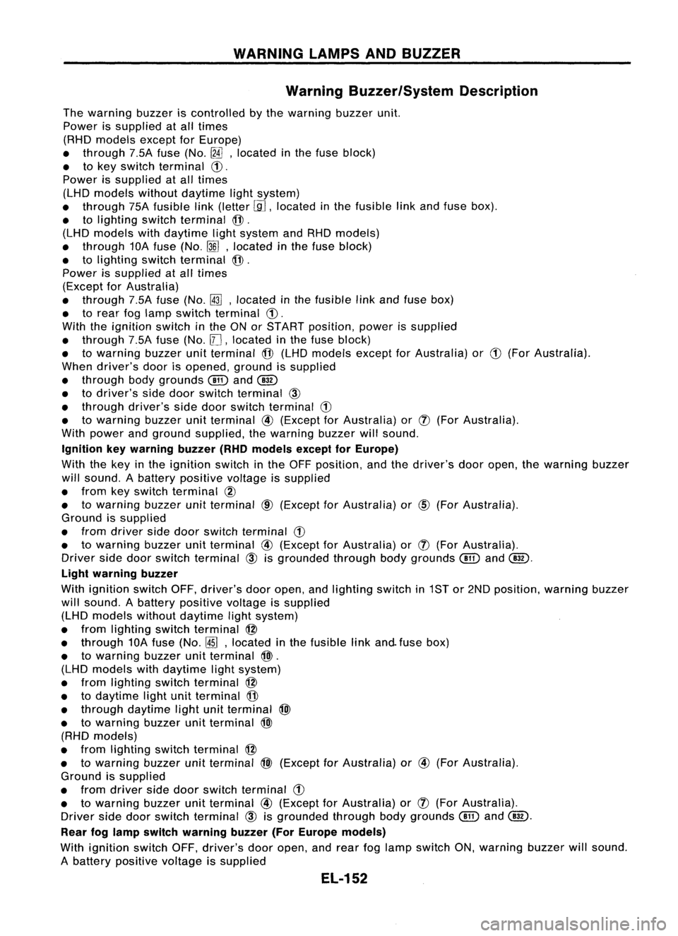
Warning Buzzer/System Description
The warning buzzeriscontrolled bythe warning buzzerunit.
Power issupplied atall times
(RHD models exceptforEurope)
• through 7.5Afuse (No.
[fA],
located inthe fuse block)
• tokey switch terminal
CD.
Power issupplied atall times
(LHD models withoutdaytime lightsystem)
• through 75Afusible link(letter
[.9J,
located inthe fusible linkand fuse box).
• tolighting switchterminal
@.
(LHD models withdaytime lightsystem andRHD models)
• through 10Afuse (No.
~J,
located inthe fuse block)
• tolighting switchterminal
@.
Power issupplied atall times
(Except forAustralia)
• through 7.5Afuse (No.~,located inthe fusible linkand fuse box)
• torear foglamp switch terminal
CD.
With theignition switchinthe ONorSTART position, powerissupplied
• through 7.5Afuse (No.
11J,
located inthe fuse block)
• towarning buzzerunitterminal
@
(LHD models exceptforAustralia) or
CD
(For Australia).
When driver's doorisopened, groundissupplied
• through bodygrounds
@
and
@
• todriver's sidedoor switch terminal
@
• through driver'ssidedoor switch terminal
G)
• towarning buzzerunitterminal
@
(Except forAustralia) or
(J)
(For Australia).
With power andground supplied, thewarning buzzerwillsound.
Ignition keywarning buzzer(RHOmodels exceptforEurope)
With thekey inthe ignition switchinthe OFF position, andthedriver's dooropen, thewarning buzzer
will sound. Abattery positive voltageissupplied
• from keyswitch terminal
CID
• towarning buzzerunitterminal
CID
(Except forAustralia) or
@)
(For Australia).
Ground issupplied
• from driver sidedoor switch terminal
G)
• towarning buzzerunitterminal
@
(Except forAustralia) or
(J)
(For Australia).
Driver sidedoor switch terminal
@
isgrounded throughbodygrounds
@
and
@.
Light warning buzzer
With ignition switchOFF,driver's dooropen, andlighting switchin1ST or2ND position, warningbuzzer
will sound. Abattery positive voltageissupplied
(LHD models withoutdaytime lightsystem)
• from lighting switchterminal
@
• through 10Afuse (No.
@ID,
located inthe fusible linkand. fuse box)
• towarning buzzerunitterminal
@>.
(LHD models withdaytime lightsystem)
• from lighting switchterminal
@
• todaytime lightunitterminal
@
• through daytime lightunitterminal
@>
• towarning buzzerunitterminal
@>
(RHD models)
• from lighting switchterminal
@
• towarning buzzerunitterminal
@>
(Except forAustralia) or
@
(For Australia).
Ground issupplied
• from driver sidedoor switch terminal
G)
• towarning buzzerunitterminal
@
(Except forAustralia) or
(J)
(For Australia).
Driver sidedoor switch terminal
@
isgrounded throughbodygrounds
(!ill
and
@.
Rear foglamp switch warning buzzer(ForEurope models)
With ignition switchOFF,driver's dooropen, andrear foglamp switch ON,warning buzzerwillsound.
A battery positive voltageissupplied
EL-152
Page 527 of 1701
WARNINGLAMPSANDBUZZER
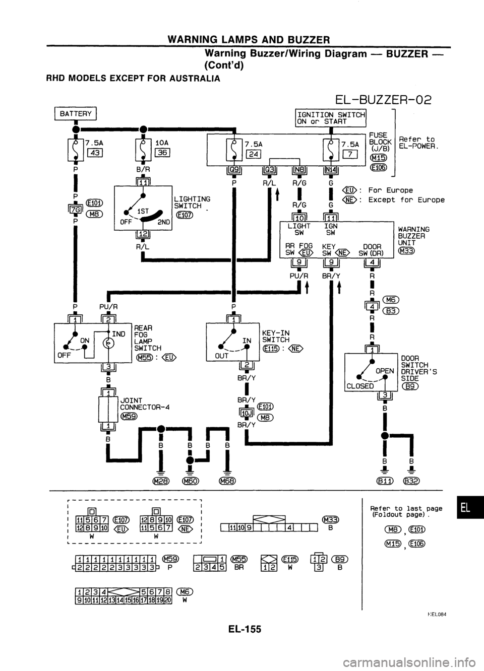
Warning Buzzer/Wiring Diagram-BUZZER -
(Cont'd)
RHO MODELS EXCEPTFORAUSTRALIA
DOOR
SWITCH
DRIVER'S
SIDE
em:>
Refer
to
EL-POWER.
WARNING
BUZZER
UNIT
(M33)
OPEN
FUSE
BLOCK
(JIB)
(E106)
For Europe
Except forEurope
DOOR
SW (DR)
~
R
I
R
~@
1C}l1C@
R
I
R
m
CLOSED
l!:j:!J
B
I
i.
8 8
-!-
-!-
(811) (832)
EL-BUZZER-02
KEY
SW@
IbjdJ
BR/Y
t
KEY-IN
IN SWITCH
@:@
RR
FOG
SW@
IbjdJ
PU/R
It
~
BR/Y
I
BR/Y ~ (E10t)
I~ICBID
BR/Y
LIGHTING
SWITCH
(E107)
I
PU/R
m
REAR
IND FOG
LAMP SWITCH
~: @
OUT
~ B
(1)
1
JOINT
CONNECTOR-4
(M59)
U
1 ,.
n
B BB B
1
t..J
1
~
OFF
I
BATTERY
I
•
~.7.1 ~.~A.I-_.~
t:1
P B/R
I
frill
P
~llli:D
I~ICMID
P
Refertolast page •
(Foldout page).
CHID
(E101)
,
,
IIfIIIITIillTII
@~ ~~
(E115)
rffll
@)
~P ~BR
ITJ:g]
W
m
B
~:EL084
EL-155
Page 528 of 1701
WARNINGLAMPSANDBUZZER
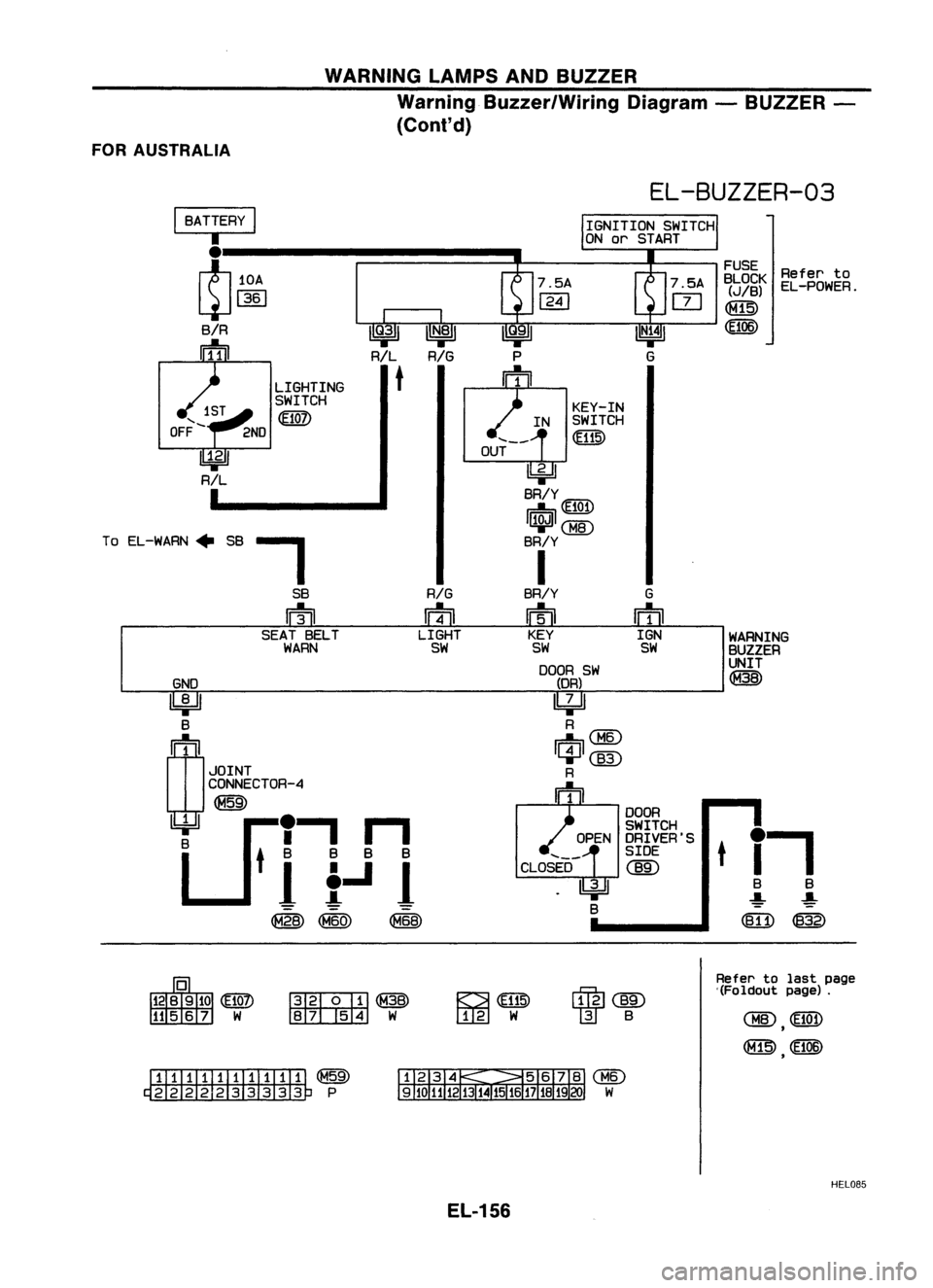
Warning Buzzer/Wiring Diagram-BUZZER -
(ConI' d)
FOR AUSTRALIA
GND
~ B
rn
1
JOINT
CONNECTOR-4
~
U
'I
n
8
tit.Ji
@
to
EL-POWER.
WARNING
BUZZER
UNIT
@
FUSE
BLOCK
(JIB)
~
t
i-,
B B
-:!:- ~
([fi) ~
EL-BUZZER-03
KEY-IN
IN SWITCH
@
OUT
~
BR/Y
~ 101
~CBID
BR/Y
I
BR/Y G
m
ffi
KEY IGN
SW SW
DOOR SW
(DR)
~
R
Ii1=nCBID
~@)
R
m
DOOR
SWITCH
OPEN DRIVER'S
SIDE
CLOSED
@)
~
B
LIGHTING
SWITCH
m
-,
SB
RIG
rn
ffi
SEAT BELT LIGHT
WARN SW
I
BATTERY
I
I
~10A
L:J
1361
SiR
rrfnJ
To EL-WARN" SB
~@
~W
~
[I[g]
W
~@)
W
B
Refer
tolast page
'(Foldout page).
ITIillJIIIIII1T ~
~P
HEL085
EL-156
Page 627 of 1701

NATS(Nissan Anti-Theft System)
Trouble Diagnoses (Cont'd)
SYMPTOM MATRIXCHART1
(Self-diagnosis relateditem)
X:Possibility item.'MIL: Malfunction IndicatorLamp
SYMPTOM
SYSTEM REFERENCEPART
Displayed"SELF-
DIAGNOSTIC PROCE-
(Malfunctioning NO.OFILLUSTRA-
•Blinking ofMIL'. •
Blinking ofMIL'.
DIAGRESULTS" on
DURE
part ormode) TIONONNEXT PAGE
•Engine willstart. •
Hard tostart
CONSULTscreen.
(Referencepage)
engine.
IMMU A
X IMMUPROCEDURE
1
(EL-257)
ECM BX
ECMPROCEDURE
2
(EL-257)
Open circuit inbat-
tery voltage lineof C1
X
IMMU circuit
Open circuit inigni-
.
tion lineofIMMU cir- C2
X
cuit
Open circuit in
ground lineofIMMU
C3 X
circuit
Open circuit incom-
munication line
C4
X
between IMMUand
ECM CHAINOFECM-
PROCEDURE3
Short circuit between IMMU
(EL-258)
IMMU andECM com-
C4
X
munication lineand
battery voltage line
Short circuit between
IMMU andECM com-
C4 X
munication lineand
ground line
Open circuit inpower
source lineofANTI E3
X
AMP circuit
ECM B X
IMMU A
X
Unregistered key 0 X
PROCEDURE4
DIFFERENCE OFKEY
IMMU A
X
(EL-260)
Communication line
between ANT
I
AMP
E1
X
and IMMU:
Open circuit orshort
circuit ofbattery volt-
age lineorshort cir- E2
X
cuit ofground line
Open circuit inpower
source lineofANTI E3
X
PROCEDURE5
AMP circuit CHAIN
OFIMMU-KEY
(EL-261)
Open circuit in
ground lineofANTI E4
X
AMP circuit
Malfunction ofkey 10
E5 X
chip
IMMU A
X
Antenna amp. E6
X
EL-255
•
Page 765 of 1701
ON-BOARDDIAGNOSTIC SYSTEMDESCRIPTION @KJ
Malfunction Indicatorlamp(Mil)(Cont'd)
DIAGNOSTIC TESTMODE I-BULB CHECK
In this mode, theMALFUNCTION INDICATORLAMPonthe instrument panelshould stayON.Ifitremains
OFF, check thebulb. Refer toEL section ("WARNING LAMPSANDCHIME") orsee EC-223.
DIAGNOSTIC TESTMODE I-MALFUNCTION WARNING
MALFUNCTION INDICATORLAMP
ON
OFF Condition
Engine coolant temperature sensorcircuitmalfunction oroverheating isdetected, or
the ECM's CPUismalfunctioning.
No malfunction.
• These Diagnostic TroubleCodeNumbers areclarified inDiagnostic TestMode II(SELF-DIAGNOS-
TIC RESULTS).
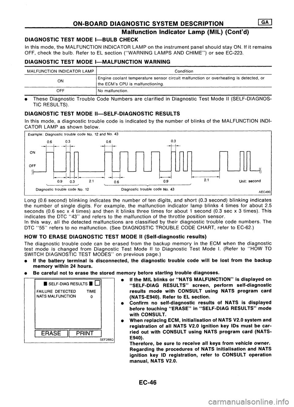
DIAGNOSTIC TESTMODE II-SELF-DIAGNOSTIC RESULTS
In this mode, adiagnostic troublecodeisindicated bythe number ofblinks ofthe MALFUNCTION INDI-
CATOR LAMPasshown below.
Example: Diagnostic troublecodeNo.12and No.43
ON
0.6
03
111-'1
0.6
II
0.3
OFF
j
~
~~ -I.
--.1
-4--1--
Q9 O~ 21 OB Q9
'--------v----' '--------v------~
Diagnostic troublecodeNo.12 DiagnostictroublecodeNo.43
2.1
Unit:second
AEC490
• SELF-DIAG RESULTS.
0
FAILURE DETECTED TIME
NATS MALFUNCTION
0
I
ERASE
II
PRINT
I
SEF288Q
Long
(0.6second) blinkingindicates thenumber often digits, andshort (0.3second) blinkingindicates
the number ofsingle digits. Forexample, themalfunction indicatorlampblinks 4times forabout 2.5
seconds (0.6secx4 times) andthen itblinks threetimes forabout 1second (0.3secx3 times). This
indicates theDTC "43" andrefers tothe malfunction ofthe throttle position sensor.
In this way, allthe detected malfunctions areclassified bytheir diagnostic troublecodenumbers. The
DTC "55" refers tono malfunction. (SeeDIAGNOSTIC TROUBLECODECHART, refertoEC-62.)
HOW TOERASE DIAGNOSTIC TESTMODE II(Self-diagnostic results)
The diagnostic troublecodecanbeerased fromthebackup memory inthe ECM when thediagnostic
test mode ischanged fromDiagnostic TestMode IIto Diagnostic TestMode
I.
(Refer to"HOW TO
SWITCH DIAGNOSTIC TESTMODES" onprevious page.)
• Ifthe battery terminal isdisconnected, thediagnostic troublecodewillbelost from thebackup
memory within24hours.
• Becareful nottoerase thestored memory before
startin~
troublediagnoses.
• If
the MIL blinks or"NATS MALFUNCTION" isdisplayed on
"SELF-OIAG RESULTS"screen,perform self-diagnostic
results modewithCONSULT usingNATS program card
(NATS-E940). RefertoEL section.
• Confirm noself-diagnostic resultsofNATS isdisplayed
before touching "ERASE" in"SELF-DIAG RESULTS"mode
with CONSULT.
• When replacing ECM,initialisation ofNATS V2.0system and
registration ofall NATS V2.0ignition key10smust becar-
ried outwith CONSULT usingNATS program card(NATS-
E940).
Therefore, besure toreceive allkeys from vehicle owner.
Regarding theprocedures ofNATS initialisation andNATS
ignition key10registration, refertoCONSULT operation
manual, NATS V2.0.
EC-46
Page 971 of 1701
ON-BOARDDIAGNOSTIC SYSTEMDESCRIPTION ~
Malfunction IndicatorLamp(MIL)(Cont'd)
DIAGNOSTIC TESTMODE I-BULB CHECK
In this mode, theMALFUNCTION INDICATORLAMPonthe instrument panelshould stayON.If
it
remains
OFF, check thebulb. Refer toEL section ("WARNING LAMPSANDCHIME") orsee EC-370.
DIAGNOSTIC TESTMODE I-MALFUNCTION WARNING
MALFUNCTION INDICATORLAMP
ON
OFF Condition
Engine coolant temperature sensorcircuitmalfunction isdetected, orthe ECM's CPU
is malfunctioning.
No malfunction.
• These Diagnostic TroubleCodeNumbers areclarified inDiagnostic TestMode II(SELF-DIAGNOS-
TIC RESULTS).
DIAGNOSTIC TESTMODE II-SELF-DIAGNOSTIC RESULTS
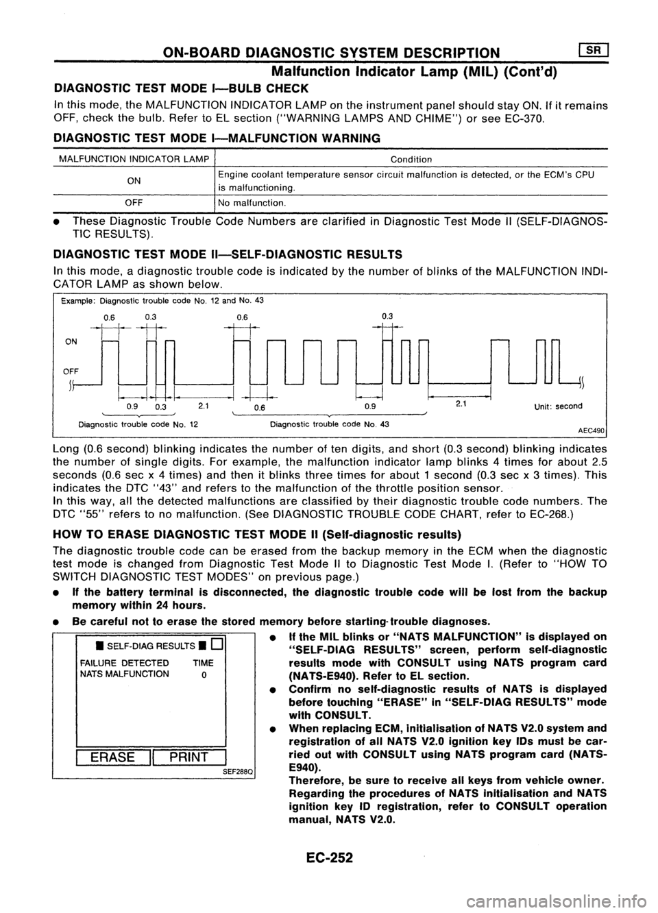
In this mode, adiagnostic troublecodeisindicated bythe number ofblinks ofthe MALFUNCTION INDI-
CATOR LAMPasshown below.
Example: Diagnostic troublecodeNo.12and No.43
0.6 0.3
ON
1111
OFF ~
0.9 0.3
0.6
--I~
2.1 0.6
0.9
0.3
Unit:second
Diagnostic troublecodeNo.12 Diagnostic
troublecodeNo.43
AEC490
• SELF-DIAG RESULTS.
0
FAILURE DETECTED TIME
NATS MALFUNCTION
0
I
ERASE
II
PRINT
I
SEF288Q
Long
(0.6second) blinkingindicates thenumber often digits, andshort (0.3second) blinkingindicates
the number ofsingle digits.Forexample, themalfunction indicatorlampblinks 4times forabout 2.5
seconds (0.6secx4times) andthen itblinks threetimes forabout 1second (0.3sec x3 times). This
indicates theDTC "43" andrefers tothe malfunction ofthe throttle position sensor.
In this way, allthe detected malfunctions areclassified bytheir diagnostic troublecodenumbers. The
DTC "55" refers tono malfunction. (SeeDIAGNOSTIC TROUBLECODECHART, refertoEC-268.)
HOW TOERASE DIAGNOSTIC TESTMODE II(Self-diagnostic results)
The diagnostic troublecodecanbeerased fromthebackup memory inthe ECM when thediagnostic
test mode ischanged fromDiagnostic TestMode IIto Diagnostic TestMode
I.
(Refer to"HOW TO
SWITCH DIAGNOSTIC TESTMODES" onprevious page.)
• Ifthe battery terminal isdisconnected, thediagnostic troublecodewillbelost from thebackup
memory within24hours.
• Becareful nottoerase thestored memory beforestarting- troublediagnoses.
• Ifthe MIL blinks or"NATS MALFUNCTION" isdisplayed on
"SELF-OIAG RESULTS"screen,perform self-diagnostic
results modewithCONSULT usingNATS program card
(NA TS-E940). RefertoEL section.
• Confirm noself-diagnostic resultsofNATS isdisplayed
before touching "ERASE" in"SELF-DiAG RESULTS"mode
with CONSULT.
• When replacing ECM,inltialisation ofNATS V2.0system and
registration ofall NATS V2.0 Ignition keyIDsmust becar-
ried outwith CONSULT usingNATS program card(NATS-
E940).
Therefore, besure toreceive allkeys from vehicle owner.
Regarding theprocedures ofNATS initialisation andNATS
ignition key
10
registration, refertoCONSULT operation
manual, NATS V2.0.
EC-252
Page 1091 of 1701
VE-TVPEINJECTION PUMP
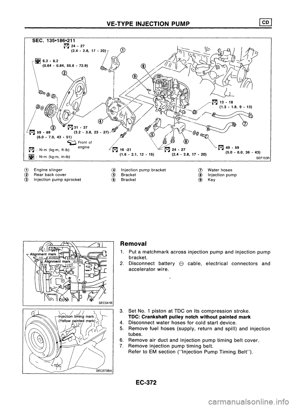
G)
Engine slinger
@
Rear backcover
@
Injection pumpsprocket
@
Injection pumpbracket
@
Bracket
@
Bracket
(J)
Water hoses
@
Injection pump
@ Key
Removal
1. Put amatchmark acrossinjection pumpandinjection pump
bracket.
2. Disconnect battery
e
cable, electrical connectors and
accelerator wire.
3. Set No.1 piston atTDe onitscompression stroke.
TOC: Crankshaft pulleynotchwithout painted mark
4. Disconnect waterhoses forcold start device.
5. Remove fuelhoses (supply, returnandspill) andinjection
tubes.
6. Remove airduct andinjection pumptiming beltcover.
7. Remove injection pumptiming belt.
Refer toEM section ("Injection PumpTiming. Belt").
EC-372
Page 1105 of 1701
ENGINEANDEMISSION CONTROL OVERALLSYSTEM
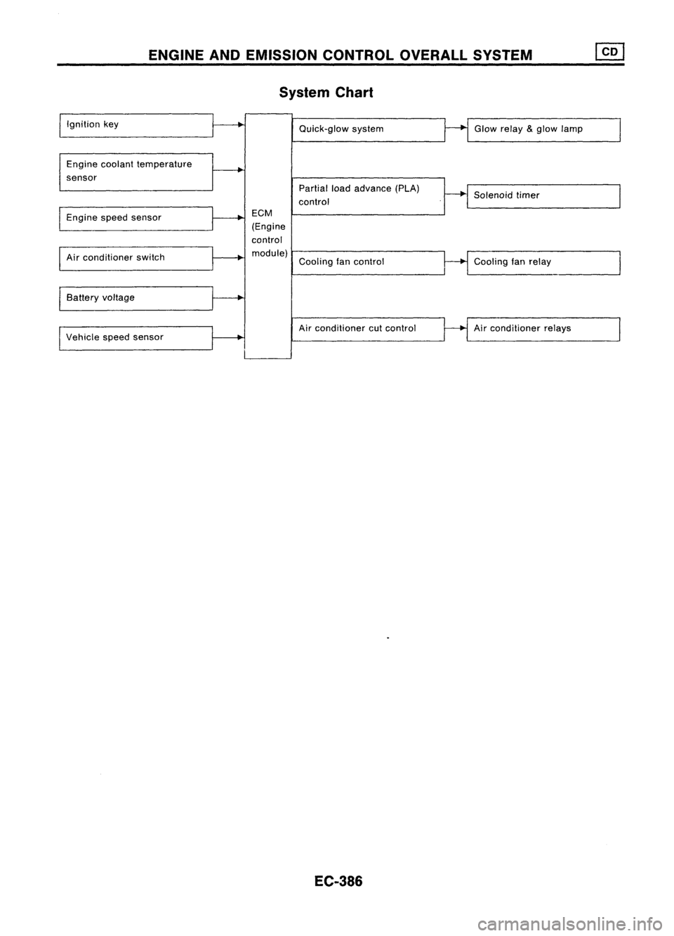
System Chart
Ignition key
Engine coolant temperature
sensor Quick-glow
system
Partial loadadvance (PLA)
control Glow
relay
&
glow lamp
Solenoid timer
Engine speedsensor
Air conditioner switch
Battery voltage
Vehicle speedsensor
ECM
(Engine
control module) Coolingfancontrol
Air conditioner cutcontrol
EC-386
Cooling
fanrelay
Air conditioner relays