1995 NISSAN ALMERA N15 key battery
[x] Cancel search: key batteryPage 1107 of 1701
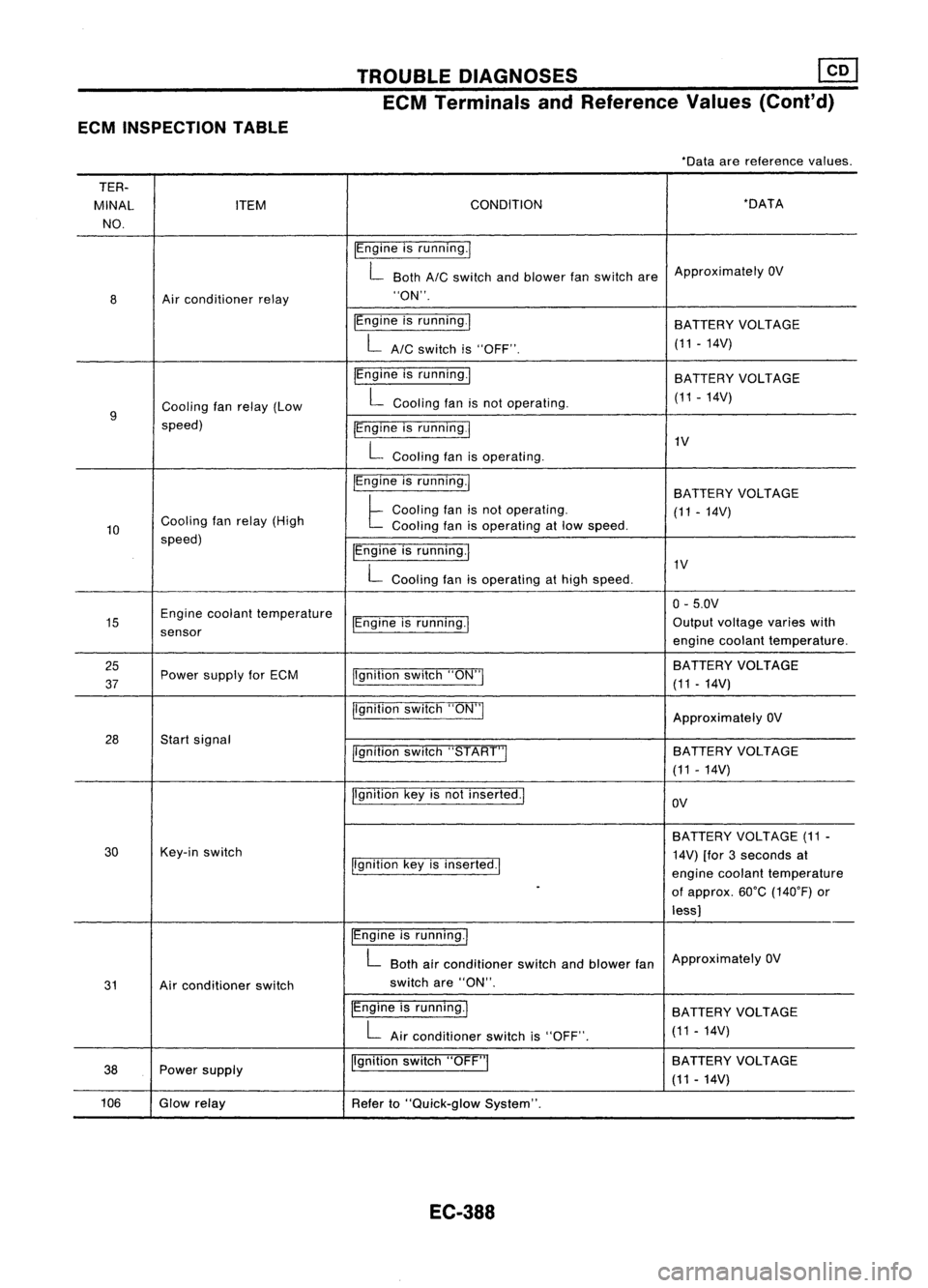
ECMINSPECTION TABLE TROUBLE
DIAGNOSES ~
ECM Terminals andReference Values(Coni'd)
-Data arereference values.
TER-
MINAL ITEM CONDITION -DATA
NO.
IEngineisrunning.1
L Both
AIC
switch andblower fanswitch areApproximately
OV
8 Air
conditioner relay "ON".
IEngine isrunning.1
BATTERYVOLTAGE
LAIC switchis"OFF". (11
-14V)
IEngine isrunning.1
BATTERY VOLTAGE
Cooling fanrelay (Low L
Cooling fanisnot operating. (11-14V)
9
speed) IEngineisrunning
I
L
Cooling fanisoperating. 1V
IEngine isrunning.1
BATTERYVOLTAGE
Cooling fanrelay (High
t
Cooling fanisnot operating.
(11-14V)
10 Cooling
fanisoperating atlow speed.
speed) IEngineisrunning.1
L
Cooling fanisoperating athigh speed. 1V
0- 5.0V
15 Engine
coolant temperature
IEngineisrunning.1 Output
voltage varieswith
sensor enginecoolant temperature.
25 jlgnitionswitch"ON"I BATTERY
VOLTAGE
37 Power
supply forECM
(11-14V)
jlgnition switch"ON"I
ApproximatelyOV
28 Startsignal
llgnitionswitch"START"I SA
TTERY VOLTAGE
(11 -14V)
Ilgnition keyisnot inserted.1
OV
BATTERY VOLTAGE (11-
30 Key-in
switch
14V)[for3seconds at
Ilgnition keyisinserted.1
enginecoolant temperature
-
ofapprox. 60°C(140°F) or
less)
IEngine isrunning.1
L
Both airconditioner switchandblower fanApproximately
OV
31 Airconditioner switch switch
are"ON".
IEngine isrunning.1
BATTERYVOLTAGE
L
Airconditioner switchis"OFF". (11
-14V)
38 Power
supply Ilgnition
switch"OFF"I BATTERY
VOLTAGE
(11 -14V)
106 Glowrelay
Referto"Quick-glow System".
EC-388
Page 1112 of 1701
![NISSAN ALMERA N15 1995 Service Manual TROUBLEDIAGNOSES
Quick-glow System(Cont'd)
•
GLOW
PLUG
(E213)
R
ctJ@
~~
R
I
R
Q
(b):
LHDmodels
<E:>:
RHOmodels
EC-GLDW-02
Refer toEL-POWER.
75A
IT]
!'e"
(ENGINE
CONTR NISSAN ALMERA N15 1995 Service Manual TROUBLEDIAGNOSES
Quick-glow System(Cont'd)
•
GLOW
PLUG
(E213)
R
ctJ@
~~
R
I
R
Q
(b):
LHDmodels
<E:>:
RHOmodels
EC-GLDW-02
Refer toEL-POWER.
75A
IT]
!'e"
(ENGINE
CONTR](/manual-img/5/57349/w960_57349-1111.png)
TROUBLEDIAGNOSES
Quick-glow System(Cont'd)
•
GLOW
PLUG
(E213)
R
ctJ@
~~
R
I
R
Q
(b):
LHDmodels
RHOmodels
EC-GLDW-02
Refer toEL-POWER.
75A
IT]
!'e"
(ENGINE
CONTROL
MODULE)
(M39)
W/L
B/R
1--~
I
W!L B/R
11!11~II~e~y
~m>
~
1!:i=Jll!:i=!J~
W/R R
I
~1
W/R W/R
CHID ~ I~ICHID
W/R W/R
tJ
I
W/R
IL@JI
G/R
+f
W/L W/L
m
rA,
~(E10f)
CHID I~I
I~ICHID
W/L W!L
tJ
I
W/L
1001
BATT
FUSE
BLOCK
(JIB)
(106)
7.5A
1241
I
BATTERY
I
•
. ------.
~ffij
10.
91
P
I
P
~1
KEY-IN
IN SWITCH
OUT--
@
~
BR/Y
I
~~
BR/Y BR/Y
(E10f) .~ ~(EiOf)
CHID
I~I
I~ICHID
BR/Y BR/Y
t-t
I
BR/Y
00 KEY
~ (E115)
[IIg]
W
~---------------~
I I
:Fnm>~~~~:
:rnJ
G
@J
W
l.9J
W:
, ,
-----------------
Refer
tolast page
(Foldout page).
HEC089
EC-393
Page 1114 of 1701
TROUBLEDIAGNOSES
Quick-glow System(Cont'd)
@
CHECK COMPONENTS NG
(Glow relay, Glowplug,Engine coolant
temperature sensor,Key-inswitch, Igni-
tion switch).
Refer to"Component Inspection"(EC-
397).
OK
Disconnect andreconnect harnesscon-
nectors inthe circuit. Thenretest.
Trouble isnot fixed.
Check ECMpinterminals fordamage or
the connection ofECM harness connec-
tor. Reconnect ECMharness connector
and retest. Replace
malfunctioning
component(s).
•
BATIERY [
Voltage
OV
Ignition
key
START
[
ON
IN [
OUT
,
,
,
I
,
JL
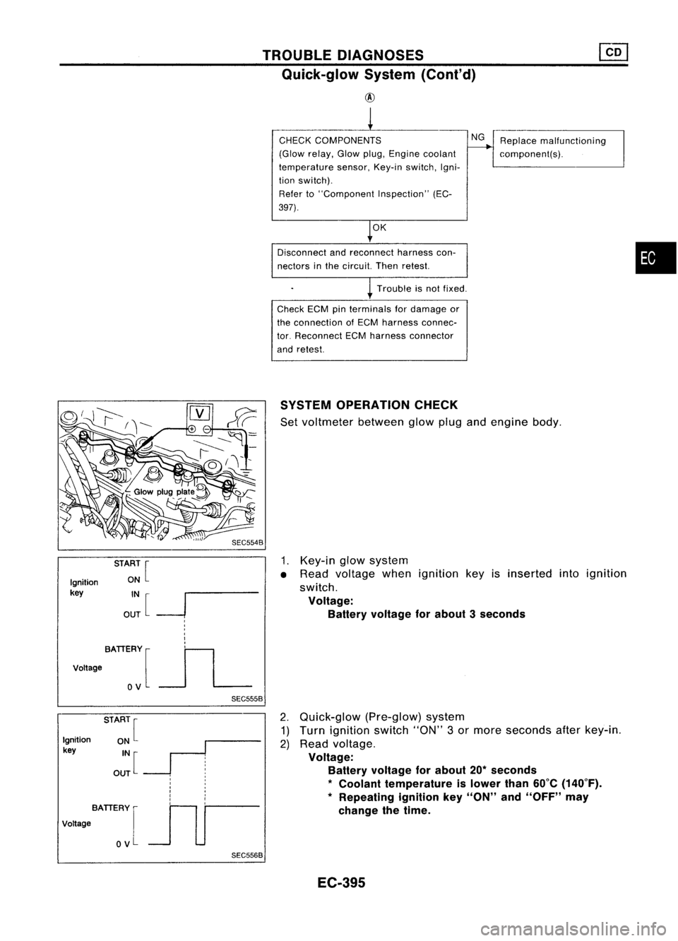
SEC5558SYSTEM
OPERATION CHECK
Set voltmeter betweenglowplugandengine body.
1. Key-in glowsystem
• Read voltage whenignition keyisinserted intoignition
switch.
Voltage: Battery voltage forabout 3seconds
Ignition
key
BATIERY [
Voltage
OV
SEC5568
2.
Quick-glow (Pre-glow)system
1) Turn ignition switch"ON"3or more seconds afterkey-in.
2) Read voltage.
Voltage: Battery voltage forabout 20*seconds
*
Coolant temperature islower than60°C(140°F).
* Repeating ignitionkey"ON" and"OFF" may
change thetime.
EC-395
Page 1115 of 1701
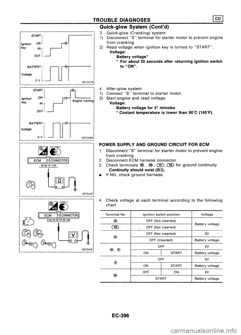
4.After-glow system
1) Connect "8"terminal tostarter motor.
2) Start engine andread voltage.
Voltage: Battery voltage for5*minutes
* Coolant temperature islower than60°C(140°F).
TROUBLE
DIAGNOSES
Quick-glow System(Cont'd)
3. Quick-glow (Cranking)system
1) Disconnect "S"terminal forstarter motortoprevent engine
from cranking.
2) Read voltage whenignition keyisturned to"8T ART".
Voltage: Battery voltage
*
*
For about 20seconds afterreturning ignitionswitch
to
"ON".
START
[
J
Ignition ON
F:
key IN
r- j
OUT
L :
I
I
I
vo,,:TIERYlJlfr
o
V
SEC557B
STA:~[
JL
Ignition
r:
Enginerunning
key IN :
OUT [
!
I
I
,
I
,
votta;ATIERY [Jlfi=
o
V
SEC558B
~i5
II
ECM E
CONNECTOR
II
26-39101-105 POWER
SUPPLY ANDGROUND CIRCUITFORECM
1. Disconnect "S"terminal forstarter motortoprevent engine
from cranking.
2. Disconnect ECMharness connector.
3. Check terminals
@,
@.
Gill.
@
forground continuity.
Continuity shouldexist(On).
• IfNG, check ground harness.
SEF943P
(D
II
~i5
ECM B
CONNECTOR
II
• 5-25-28-30-37-38-106,
4.
Check voltage ateach terminal according tothe following
chart.
Terminal No. Ignitionswitchposition
Voltage
@
OFF(Notinserted)
GID
Battery
voltage
.
OFF
(Notinserted)
OFF (Not inserted) OV
@
OFF(Inserted) Batteryvoltage
OFF OV
@,@
ONSTARTBatteryvoltage
OFF OV
@
ONSTART
Batteryvoltage
OFF ONOV
@
STARTBatteryvoltage
EC-396
Page 1116 of 1701
TROUBLEDIAGNOSES ~
Quick-glow System(Cont'd)
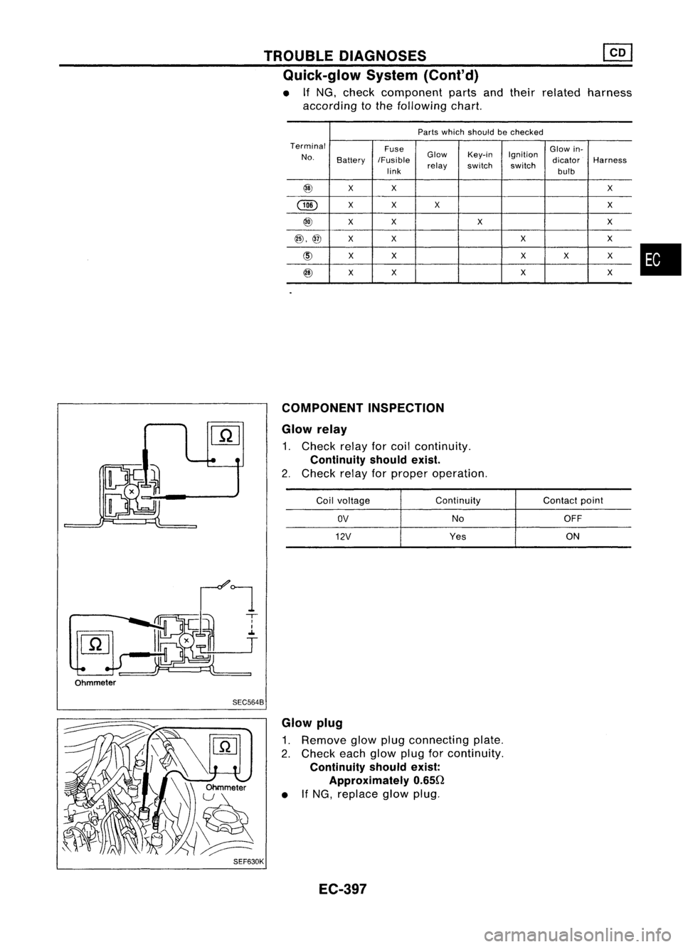
• If
NG.
check component partsandtheir related harness
according tothe following chart.
Parts which should bechecked
Terminal Fuse Glowin-
No. Battery IFusible Glow
Key-in Ignition
dicatorHarness
link relay
switch switch
bulb
@
XX
X
@
X
X X X
@
XX
X X
@,@
XX XX
@
XX X
X X
@
X
X XX
COMPONENT INSPECTION
Glow relay
1. Check relayforcoil continuity.
Continuity shouldexist.
2. Check relayforproper operation.
Coil voltage Continuity
Contactpoint
OV
NoOFF
12V
Yes ON
•
Ohmmeter SEC5648
SEF630K Glow
plug
1. Remove glowplugconnecting plate.
2. Check eachglow plugforcontinuity.
Continuity shouldexist:
Approximately 0.650
• IfNG, replace glowplug.
EC-397
Page 1358 of 1701
SEF289HSGI233
SGI234 PRECAUTIONS
General Precautions (Cont'd)
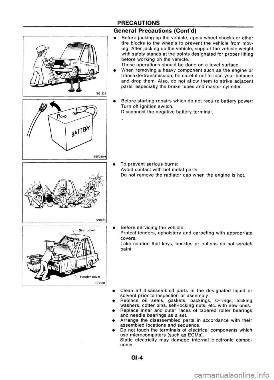
• Before jacking upthe vehicle, applywheel chocks orother
tire blocks tothe wheels toprevent thevehicle frommov-
ing. After jacking upthe vehicle, supportthevehicle weight
with safety stands atthe points designated forproper lifting
before working onthe vehicle.
These operations shouldbedone onalevel surface.
• When removing aheavy component suchasthe engine or
transaxle/transmission, becareful nottolose your balance
and drop them. Also,donot allow themtostrike adjacent
parts, especially thebrake tubesandmaster cylinder.
• Before starting repairswhichdonot require batterypower:
Turn offignition switch.
Disconnect thenegative batteryterminal.
• Toprevent seriousburns:
Avoid contact withhotmetal parts.
Do not remove theradiator capwhen theengine ishot.
• Before servicing thevehicle:
Protect fenders, upholstery andcarpeting withappropriate
covers.
Take caution thatkeys, buckles orbuttons donot scratch
paint.
• Clean alldisassembled partsinthe designated liquidor
solvent priortoinspection orassembly.
• Replace oilseals, gaskets, packings, O-rings,locking
washers, cotterpins,self-locking nuts,etc.with newones.
• Replace innerandouter races oftapered rollerbearings
and needle bearings asaset.
• Arrange thedisassembled partsinaccordance withtheir
assembled locationsandsequence.
• Donot touch theterminals ofelectrical components which
use microcomputers (suchasECMs).
Static electricity maydamage internalelectronic compo-
nents.
GI-4
Page 1379 of 1701
HOWTOPERFORM EFFICIENT DIAGNOSIS FORANELECTRICAL INCIDENT
Circuit Inspection (Cont'd)
Voltage checkmethod
1. Remove theblown fuseanddisconnect allloads (i.e.SW1 open, relaydisconnected andsolenoid •
disconnected) poweredthroughthefuse.
2. Turn theignition keytothe ONorSTART position. Verifybattery voltage atthe B
+
side ofthe fuse
terminal (oneleadonthe B
+
terminal sideofthe fuse block andone lead onaknown goodground).
3. With SW1 open andtheDMM leads across bothfuseterminals, checkforvoltage.
voltage; shortisbetween fuseblock andSW1 (point A).
no voltage; shortisfurther downthecircuit thanSW1.
4. With SW1 closed, relayandsolenoid disconnected andtheDMM leadsacross bothfuseterminals,
check forvoltage.
voltage; shortisbetween SW1andtherelay (point B).
no voltage; shortisfurther downthecircuit thantherelay.
5. With SW1 closed, relaycontacts jumpedwithfused jumper wirecheck forvoltage.
voltage; shortisdown thecircuit ofthe relay orbetween therelay andthedisconnected sole-
noid (point C).
no voltage; retracestepsandcheck power tofuse block.
GROUND INSPECTION
Ground connections arevery important tothe proper operation ofelectrical andelectronic circuits.
Ground connections areoften exposed tomoisture, dirtand other corrosive elements. Thecorrosion
(rust) canbecome anunwanted resistance. Thisunwanted resistance canchange theway acircuit
works. Electronically controlledcircuitsarevery sensitive toproper grounding. Aloose orcorroded groundcan
drastically affectanelectronically controlledcircuit.Apoor orcorroded groundcaneasily affectthecir-
cuit. Even when theground connection looksclean, therecanbeathin film ofrust onthe surface.
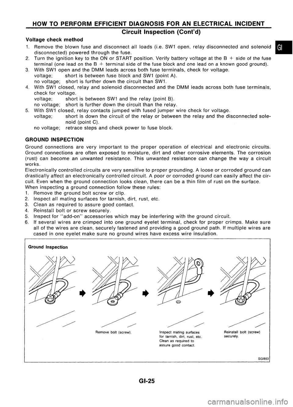
When inspecting aground connection followtheserules:
1. Remove theground boltscrew orclip.
2. Inspect allmating surfaces fortarnish, dirt,rust, etc.
3. Clean asrequired toassure goodcontact.
4. Reinstall boltorscrew securely.
5. Inspect for"add-on" accessories whichmaybeinterfering withtheground circuit.
6. Ifseveral wiresarecrimped intoone ground eyeletterminal, checkforproper crimps. Makesure
all ofthe wires areclean, securely fastened andproviding agood ground path.Ifmultiple wiresare
cased inone eyelet makesurenoground wireshaveexcess wireinsulation.
Ground Inspection
•
Removeboll(screw).
•
GI-25
Inspect
matingsurfaces
for tarnish. dirt.rust. etc.
Clean asrequired to
assure goodcontact.
•
Reinstallbolt(screw)
securely.
SGI853
Page 1385 of 1701
HOWTOFOLLOW FLOWCHART INTROUBLE DIAGNOSES
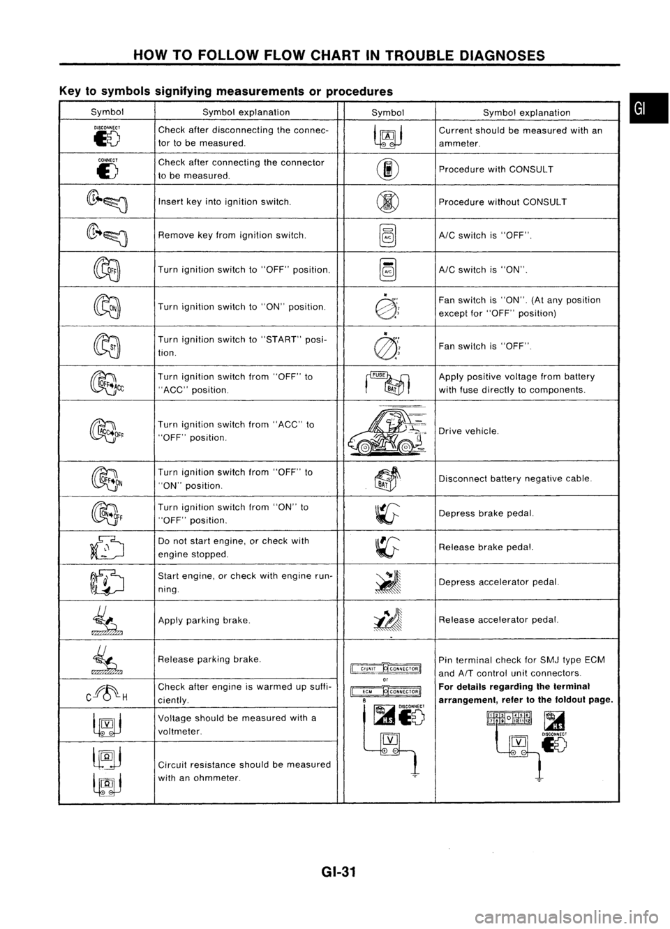
Key tosymbols signifying measurements orprocedures
Symbol Symbolexplanation
SymbolSymbolexplanation
DISCONNECT
Checkafterdisconnecting theconnec-
~
Current
shouldbemeasured withan
~8
tor
tobe measured.
ammeter.
CONNECT
Checkafterconnecting theconnector
00
E)
tobe measured. Procedure
withCONSULT
(lr~~
Insert
keyinto ignition switCh.
@
Procedure
withoutCONSULT
(lr ..~
Remove
keyfrom ignition switch.
~AIC
switch is"OFF".
~
Turn
ignition switchto"OFF" position.
~AIC
switch is"ON".
~
"
Fanswitch is"ON". (Atany position
Turn ignition switchto"ON" position.
@:;
exceptfor"OFF" position)
~ "
Turn ignition switchto"START" posi-
@'~
Fan
switch is"OFF".
tion.
~~
Turn
ignition switchfrom"OFF" to
~
Apply
positive voltagefrombattery
"ACC" position.
BA;
withfuse directly tocomponents.
~~r
Turn
ignition switchfrom"ACC" to
m-
~'~:
Drive
vehicle.
"OFF" position.
,.-=.
L
@J~ ..
~(e.-
OON
Turn
ignition switchfrom"OFF" to
~~
Disconnect
batterynegative cable.
"ON" position.
BAi
~F
Turn
ignition switchfrom"ON" to
~
Depress
brakepedal.
"OFF" position.
~
Do
not start engine, orcheck with
~
Release
brakepedal.
engine stopped.
ID
Start
engine, orcheck withengine run-
~
ning. Depress
accelerator pedal.
.
.
~
Apply
parking brake.
i!J
Release
accelerator pedal.
..
~
Release
parkingbrake.
~
Pin
terminal checkforSMJ typeECM
and
AIT
control unitconnectors
or
Cff~H
Check
afterengine iswarmed upsuffi-
~ For
details regarding theterminal
ciently.
B
arrangement,refertothe foldout page.
~io
~
Voltage
shouldbemeasured witha
lltlllliR~
t~~~18
voltmeter.
[YJ
lJ9j
.
-
Circuit resistance shouldbemeasured
lfJJ
with
anohmmeter.
~
GI-31
•