1995 JEEP YJ length
[x] Cancel search: lengthPage 1585 of 2158
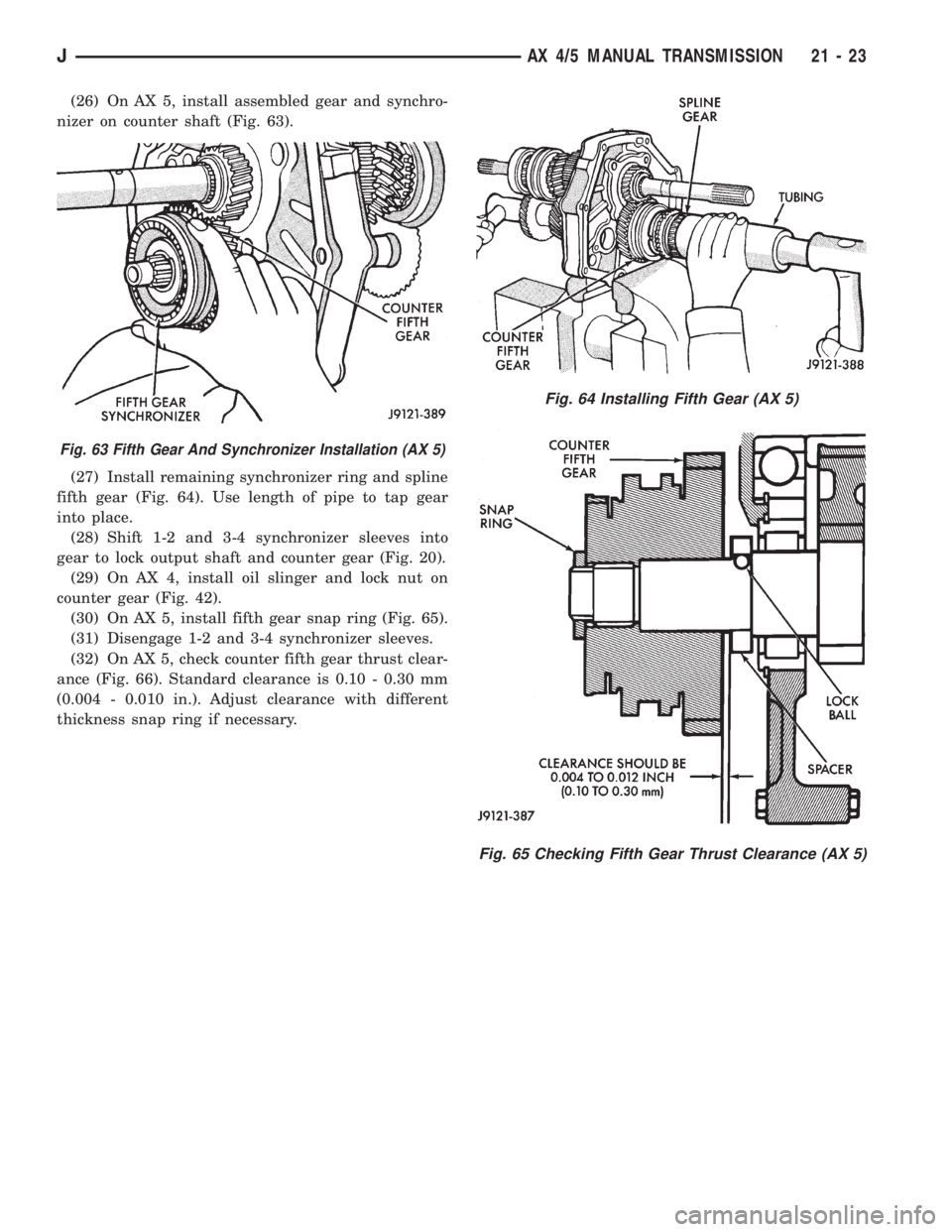
(26) On AX 5, install assembled gear and synchro-
nizer on counter shaft (Fig. 63).
(27) Install remaining synchronizer ring and spline
fifth gear (Fig. 64). Use length of pipe to tap gear
into place.
(28) Shift 1-2 and 3-4 synchronizer sleeves into
gear to lock output shaft and counter gear (Fig. 20).
(29) On AX 4, install oil slinger and lock nut on
counter gear (Fig. 42).
(30) On AX 5, install fifth gear snap ring (Fig. 65).
(31) Disengage 1-2 and 3-4 synchronizer sleeves.
(32) On AX 5, check counter fifth gear thrust clear-
ance (Fig. 66). Standard clearance is 0.10 - 0.30 mm
(0.004 - 0.010 in.). Adjust clearance with different
thickness snap ring if necessary.
Fig. 65 Checking Fifth Gear Thrust Clearance (AX 5)
Fig. 63 Fifth Gear And Synchronizer Installation (AX 5)
Fig. 64 Installing Fifth Gear (AX 5)
JAX 4/5 MANUAL TRANSMISSION 21 - 23
Page 1608 of 2158
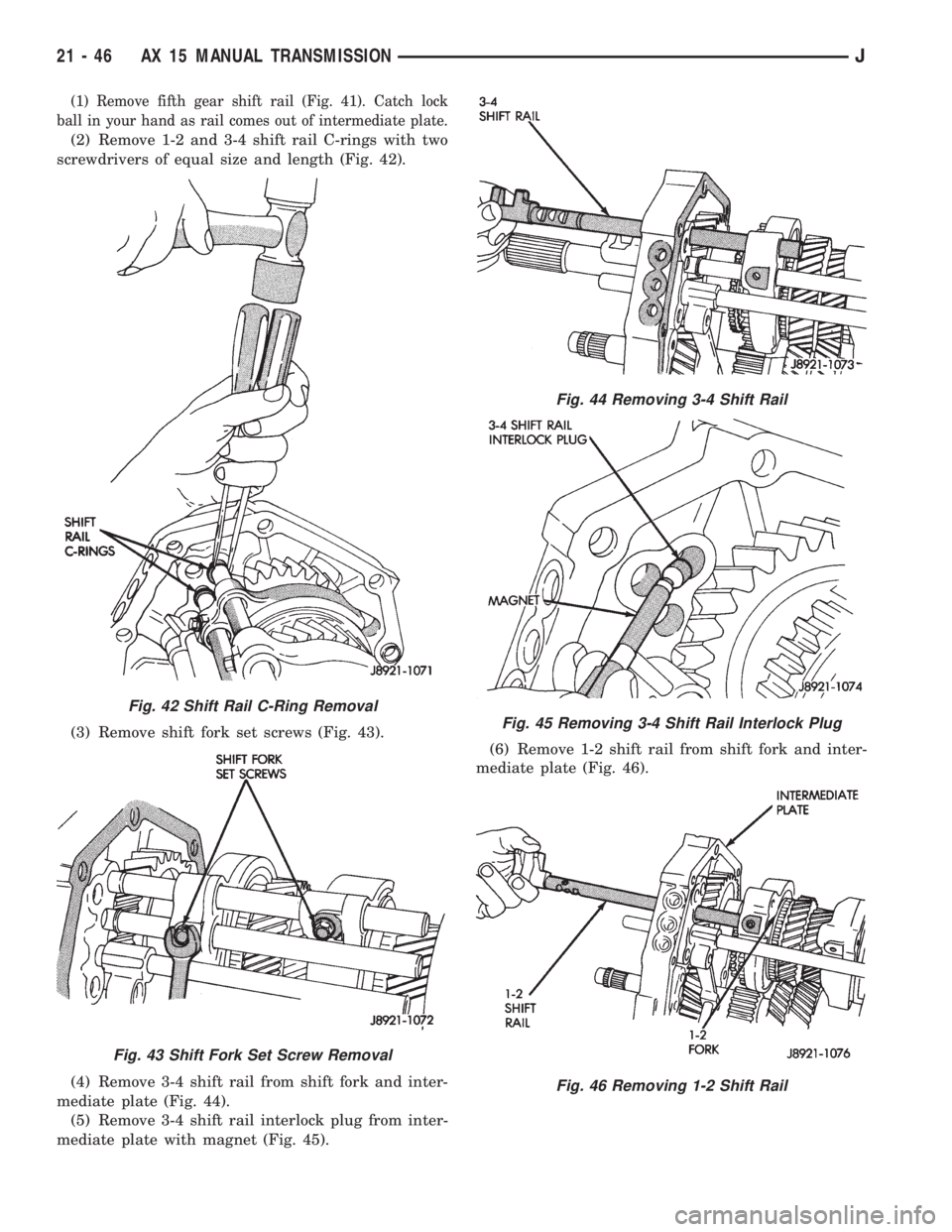
(1) Remove fifth gear shift rail (Fig. 41). Catch lock
ball in your hand as rail comes out of intermediate plate.
(2) Remove 1-2 and 3-4 shift rail C-rings with two
screwdrivers of equal size and length (Fig. 42).
(3) Remove shift fork set screws (Fig. 43).
(4) Remove 3-4 shift rail from shift fork and inter-
mediate plate (Fig. 44).
(5) Remove 3-4 shift rail interlock plug from inter-
mediate plate with magnet (Fig. 45).(6) Remove 1-2 shift rail from shift fork and inter-
mediate plate (Fig. 46).
Fig. 42 Shift Rail C-Ring Removal
Fig. 43 Shift Fork Set Screw Removal
Fig. 44 Removing 3-4 Shift Rail
Fig. 45 Removing 3-4 Shift Rail Interlock Plug
Fig. 46 Removing 1-2 Shift Rail
21 - 46 AX 15 MANUAL TRANSMISSIONJ
Page 1609 of 2158
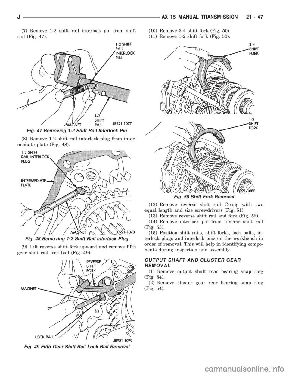
(7) Remove 1-2 shift rail interlock pin from shift
rail (Fig. 47).
(8) Remove 1-2 shift rail interlock plug from inter-
mediate plate (Fig. 48).
(9) Lift reverse shift fork upward and remove fifth
gear shift rail lock ball (Fig. 49).(10) Remove 3-4 shift fork (Fig. 50).
(11) Remove 1-2 shift fork (Fig. 50).
(12) Remove reverse shift rail C-ring with two
equal length and size screwdrivers (Fig. 51).
(13) Remove reverse shift rail and fork (Fig. 52).
(14) Remove interlock pin from reverse shift rail
(Fig. 53).
(15) Position shift rails, shift forks, lock balls, in-
terlock plugs and interlock pins on the workbench in
order of removal. This will help in identifying compo-
nents during inspection and assembly.
OUTPUT SHAFT AND CLUSTER GEAR
REMOVAL
(1) Remove output shaft rear bearing snap ring
(Fig. 54).
(2) Remove cluster gear rear bearing snap ring
(Fig. 54).
Fig. 47 Removing 1-2 Shift Rail Interlock Pin
Fig. 48 Removing 1-2 Shift Rail Interlock Plug
Fig. 49 Fifth Gear Shift Rail Lock Ball Removal
Fig. 50 Shift Fork Removal
JAX 15 MANUAL TRANSMISSION 21 - 47
Page 1629 of 2158
30RH/32RH AUTOMATIC TRANSMISSION
GENERAL INFORMATION
INDEX
page page
Recommended Fluid....................... 67
Torque Converter......................... 67
Transmission Application.................... 67
Transmission Changes and Parts Interchangeability.. 67
Transmission Controls and Components........ 67
Transmission Identification.................. 67
TRANSMISSION APPLICATION
Chrysler 30RH and 32RH automatic transmissions
are used in XJ/YJ models. Both are 3-speed auto-
matic transmissions with a gear-type oil pump, two
clutches and bands and a planetary gear system (Fig.
1).
The 30RH is used in XJ/YJ models with a 2.5L en-
gine. The 32RH is used in YJ models with a 4.0L en-
gine.
TORQUE CONVERTER
A three element, torque converter is used for all
applications. The converter consists of an impeller,
stator, and turbine.
The converter used with 30RH/32RH transmissions
has a converter clutch. The clutch is engaged by an
electrical solenoid and mechanical module on the
valve body. The solenoid is operated by the power-
train control module.
The torque converter is a welded assembly and is
not a repairable component. The converter is serviced
as an assembly.
RECOMMENDED FLUID
The recommended and preferred fluid for 30RH/
32RH transmissions is Mopar ATF Plus, Type 7176.
Dexron II is not really recommended and should
only be used when ATF Plus is not available.
TRANSMISSION IDENTIFICATION
The transmission identification numbers are
stamped on the left side of the case just above the oil
pan gasket surface (Fig. 2). The first set of numbers
is the transmission part number. The next set of code
numbers set is the date of build. The final set of code
numbers represents the transmission serial number.
TRANSMISSION CHANGES AND PARTS
INTERCHANGEABILITY
1995 transmissions are similar to previous models
but only in appearance. Current transmissions are
dimensionally different. Do not interchange new/oldparts. Different dimensions, fluid passages, input/
output shafts, cases, bands, valve bodies and gover-
nor assemblies are just a few of the changed items.
CAUTION: Special bolts are used to attach the
driveplate to the crankshaft on models with a 2.5L
engine and 30RH transmission,. These bolts have a
smaller hex head for torque converter clearance.
DO NOT interchange these bolts with similar size
bolts for any reason.
Different governor weight assemblies are used in
30RH/32RH transmissions. The 30RH weight assem-
bly is much the same as in previous years. However,
the 32RH has a three stage governor weight assem-
bly consisting of the outer weight, a smaller weight
spring, and a new intermediate weight. Refer to the
overhaul and in-vehicle service sections for more de-
tailed information.
Plastic check balls are now used in many 30RH/
32RH valve bodies. The new check balls entered pro-
duction as a running change. Plastic and steel check
balls are not interchangeable.
A converter drainback check valve has been added
to the fluid cooler system. The one-way valve is lo-
cated in the transmission outlet (pressure) line. The
valve prevents fluid drainback when the vehicle is
parked for lengthy periods.
TRANSMISSION CONTROLS AND COMPONENTS
The transmission hydraulic control system per-
forms five basic functions, which are:
²pressure supply
²pressure regulation
²flow control
²clutch/band apply and release
²lubrication
Pressure Supply And Regulation
The oil pump generates the fluid working pressure
needed for operation and lubrication. The pump is
J30RH/32RH AUTOMATIC TRANSMISSION 21 - 67
Page 1638 of 2158
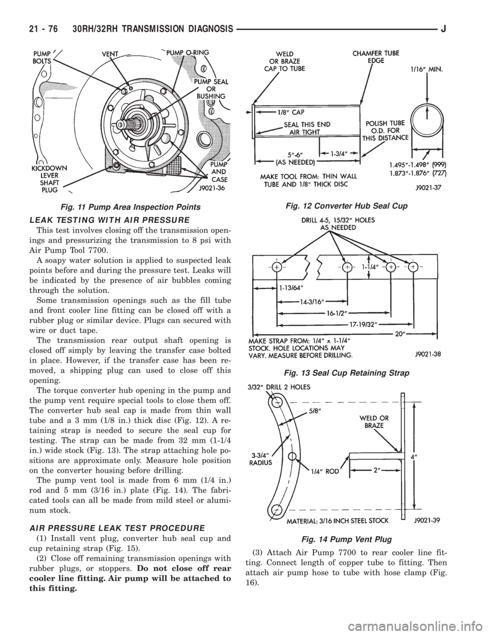
LEAK TESTING WITH AIR PRESSURE
This test involves closing off the transmission open-
ings and pressurizing the transmission to 8 psi with
Air Pump Tool 7700.
A soapy water solution is applied to suspected leak
points before and during the pressure test. Leaks will
be indicated by the presence of air bubbles coming
through the solution.
Some transmission openings such as the fill tube
and front cooler line fitting can be closed off with a
rubber plug or similar device. Plugs can secured with
wire or duct tape.
The transmission rear output shaft opening is
closed off simply by leaving the transfer case bolted
in place. However, if the transfer case has been re-
moved, a shipping plug can used to close off this
opening.
The torque converter hub opening in the pump and
the pump vent require special tools to close them off.
The converter hub seal cap is made from thin wall
tube anda3mm(1/8 in.) thick disc (Fig. 12). A re-
taining strap is needed to secure the seal cup for
testing. The strap can be made from 32 mm (1-1/4
in.) wide stock (Fig. 13). The strap attaching hole po-
sitions are approximate only. Measure hole position
on the converter housing before drilling.
The pump vent tool is made from 6 mm (1/4 in.)
rod and 5 mm (3/16 in.) plate (Fig. 14). The fabri-
cated tools can all be made from mild steel or alumi-
num stock.
AIR PRESSURE LEAK TEST PROCEDURE
(1) Install vent plug, converter hub seal cup and
cup retaining strap (Fig. 15).
(2) Close off remaining transmission openings with
rubber plugs, or stoppers.Do not close off rear
cooler line fitting. Air pump will be attached to
this fitting.(3) Attach Air Pump 7700 to rear cooler line fit-
ting. Connect length of copper tube to fitting. Then
attach air pump hose to tube with hose clamp (Fig.
16).
Fig. 11 Pump Area Inspection PointsFig. 12 Converter Hub Seal Cup
Fig. 13 Seal Cup Retaining Strap
Fig. 14 Pump Vent Plug
21 - 76 30RH/32RH TRANSMISSION DIAGNOSISJ
Page 1671 of 2158
Inspection
Check the sprag shaft for scores and for free move-
ment in the housing and sprag.
Check the sprag and control rod springs for loss of
tension or distortion. Check the square lug on the
sprag for broken edges. Check the lugs on the gover-
nor support (park gear) for broken edges. Replace
any park lock components that are worn or damaged.
Check the knob on the end of the control rod for
nicks, burrs and free turning. Replace the rod if the
knob is grooved, or worn, or if the rod is bent. The
park lock rods used in Chrysler 3-speed transmis-
sions are different lengths. If the rod must be re-
placed, be sure to install the correct length and
shape rod.
COMPONENT INSTALLATION
(1) Install park lock rod on valve body.
(2) Install reaction plug and pin assembly in the
housing and install the snap ring.
(3) Position sprag and spring in housing and in-
stall sprag shaft. Be sure square lug on sprag is fac-
ing park gear and that spring is positioned so it
moves sprag away from park gear.
(4) Install valve body.
(5) Install adapter housing and transfer case.
PARK/NEUTRAL POSITION SWITCH SERVICE
The starter feed circuit of the switch is through the
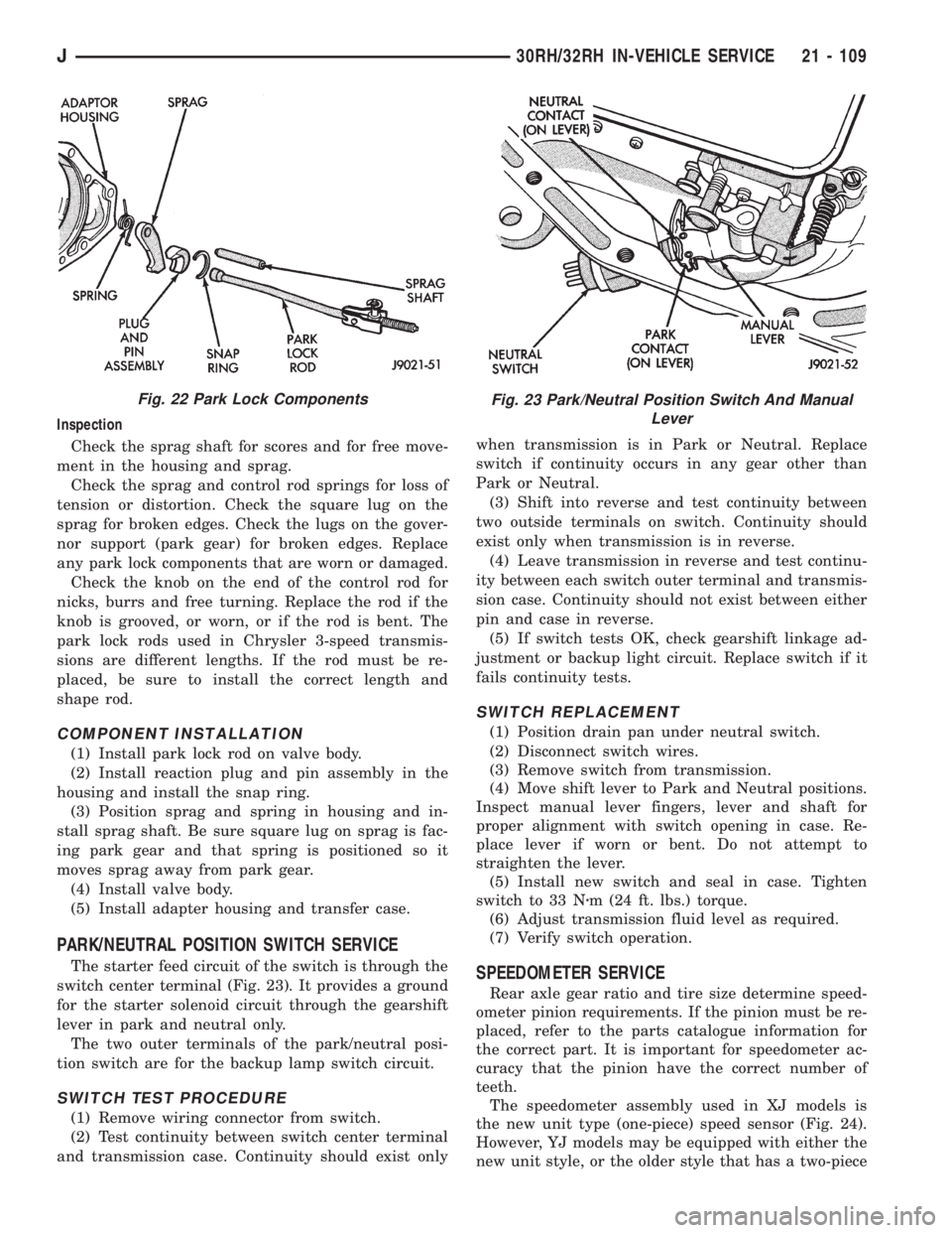
switch center terminal (Fig. 23). It provides a ground
for the starter solenoid circuit through the gearshift
lever in park and neutral only.
The two outer terminals of the park/neutral posi-
tion switch are for the backup lamp switch circuit.
SWITCH TEST PROCEDURE
(1) Remove wiring connector from switch.
(2) Test continuity between switch center terminal
and transmission case. Continuity should exist onlywhen transmission is in Park or Neutral. Replace
switch if continuity occurs in any gear other than
Park or Neutral.
(3) Shift into reverse and test continuity between
two outside terminals on switch. Continuity should
exist only when transmission is in reverse.
(4) Leave transmission in reverse and test continu-
ity between each switch outer terminal and transmis-
sion case. Continuity should not exist between either
pin and case in reverse.
(5) If switch tests OK, check gearshift linkage ad-
justment or backup light circuit. Replace switch if it
fails continuity tests.
SWITCH REPLACEMENT
(1) Position drain pan under neutral switch.
(2) Disconnect switch wires.
(3) Remove switch from transmission.
(4) Move shift lever to Park and Neutral positions.
Inspect manual lever fingers, lever and shaft for
proper alignment with switch opening in case. Re-
place lever if worn or bent. Do not attempt to
straighten the lever.
(5) Install new switch and seal in case. Tighten
switch to 33 Nzm (24 ft. lbs.) torque.
(6) Adjust transmission fluid level as required.
(7) Verify switch operation.
SPEEDOMETER SERVICE
Rear axle gear ratio and tire size determine speed-
ometer pinion requirements. If the pinion must be re-
placed, refer to the parts catalogue information for
the correct part. It is important for speedometer ac-
curacy that the pinion have the correct number of
teeth.
The speedometer assembly used in XJ models is
the new unit type (one-piece) speed sensor (Fig. 24).
However, YJ models may be equipped with either the
new unit style, or the older style that has a two-piece
Fig. 22 Park Lock ComponentsFig. 23 Park/Neutral Position Switch And Manual
Lever
J30RH/32RH IN-VEHICLE SERVICE 21 - 109
Page 1675 of 2158
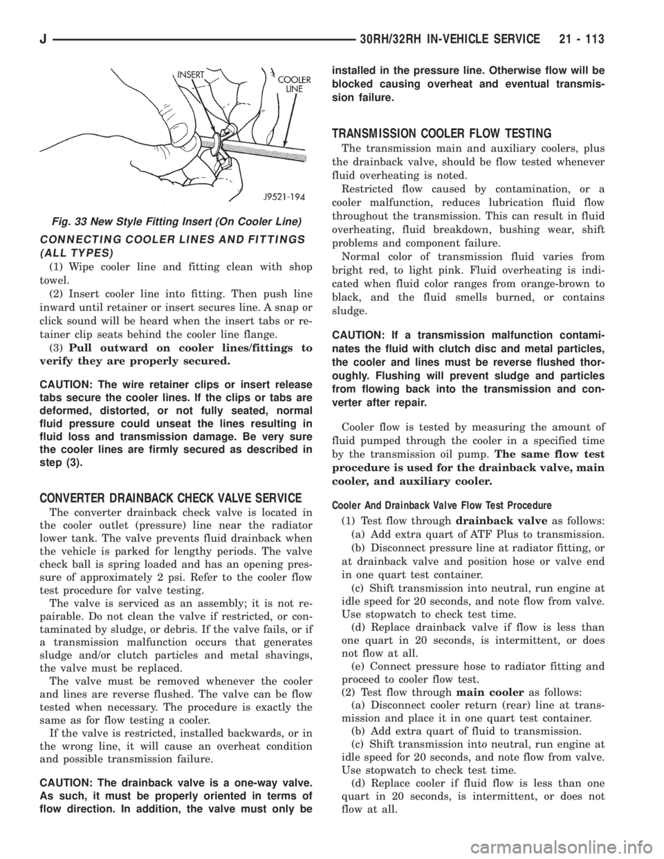
CONNECTING COOLER LINES AND FITTINGS
(ALL TYPES)
(1) Wipe cooler line and fitting clean with shop
towel.
(2) Insert cooler line into fitting. Then push line
inward until retainer or insert secures line. A snap or
click sound will be heard when the insert tabs or re-
tainer clip seats behind the cooler line flange.
(3)Pull outward on cooler lines/fittings to
verify they are properly secured.
CAUTION: The wire retainer clips or insert release
tabs secure the cooler lines. If the clips or tabs are
deformed, distorted, or not fully seated, normal
fluid pressure could unseat the lines resulting in
fluid loss and transmission damage. Be very sure
the cooler lines are firmly secured as described in
step (3).
CONVERTER DRAINBACK CHECK VALVE SERVICE
The converter drainback check valve is located in
the cooler outlet (pressure) line near the radiator
lower tank. The valve prevents fluid drainback when
the vehicle is parked for lengthy periods. The valve
check ball is spring loaded and has an opening pres-
sure of approximately 2 psi. Refer to the cooler flow
test procedure for valve testing.
The valve is serviced as an assembly; it is not re-
pairable. Do not clean the valve if restricted, or con-
taminated by sludge, or debris. If the valve fails, or if
a transmission malfunction occurs that generates
sludge and/or clutch particles and metal shavings,
the valve must be replaced.
The valve must be removed whenever the cooler
and lines are reverse flushed. The valve can be flow
tested when necessary. The procedure is exactly the
same as for flow testing a cooler.
If the valve is restricted, installed backwards, or in
the wrong line, it will cause an overheat condition
and possible transmission failure.
CAUTION: The drainback valve is a one-way valve.
As such, it must be properly oriented in terms of
flow direction. In addition, the valve must only beinstalled in the pressure line. Otherwise flow will be
blocked causing overheat and eventual transmis-
sion failure.
TRANSMISSION COOLER FLOW TESTING
The transmission main and auxiliary coolers, plus
the drainback valve, should be flow tested whenever
fluid overheating is noted.
Restricted flow caused by contamination, or a
cooler malfunction, reduces lubrication fluid flow
throughout the transmission. This can result in fluid
overheating, fluid breakdown, bushing wear, shift
problems and component failure.
Normal color of transmission fluid varies from
bright red, to light pink. Fluid overheating is indi-
cated when fluid color ranges from orange-brown to
black, and the fluid smells burned, or contains
sludge.
CAUTION: If a transmission malfunction contami-
nates the fluid with clutch disc and metal particles,
the cooler and lines must be reverse flushed thor-
oughly. Flushing will prevent sludge and particles
from flowing back into the transmission and con-
verter after repair.
Cooler flow is tested by measuring the amount of
fluid pumped through the cooler in a specified time
by the transmission oil pump.The same flow test
procedure is used for the drainback valve, main
cooler, and auxiliary cooler.
Cooler And Drainback Valve Flow Test Procedure
(1) Test flow throughdrainback valveas follows:
(a) Add extra quart of ATF Plus to transmission.
(b) Disconnect pressure line at radiator fitting, or
at drainback valve and position hose or valve end
in one quart test container.
(c) Shift transmission into neutral, run engine at
idle speed for 20 seconds, and note flow from valve.
Use stopwatch to check test time.
(d) Replace drainback valve if flow is less than
one quart in 20 seconds, is intermittent, or does
not flow at all.
(e) Connect pressure hose to radiator fitting and
proceed to cooler flow test.
(2) Test flow throughmain cooleras follows:
(a) Disconnect cooler return (rear) line at trans-
mission and place it in one quart test container.
(b) Add extra quart of fluid to transmission.
(c) Shift transmission into neutral, run engine at
idle speed for 20 seconds, and note flow from valve.
Use stopwatch to check test time.
(d) Replace cooler if fluid flow is less than one
quart in 20 seconds, is intermittent, or does not
flow at all.
Fig. 33 New Style Fitting Insert (On Cooler Line)
J30RH/32RH IN-VEHICLE SERVICE 21 - 113
Page 1768 of 2158
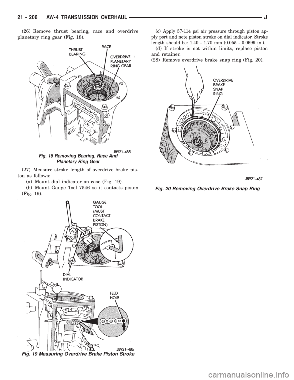
(26) Remove thrust bearing, race and overdrive
planetary ring gear (Fig. 18).
(27) Measure stroke length of overdrive brake pis-
ton as follows:
(a) Mount dial indicator on case (Fig. 19).
(b) Mount Gauge Tool 7546 so it contacts piston
(Fig. 19).(c) Apply 57-114 psi air pressure through piston ap-
ply port and note piston stroke on dial indicator. Stroke
length should be: 1.40 - 1.70 mm (0.055 - 0.0699 in.).
(d) If stroke is not within limits, replace piston
and retainer.
(28) Remove overdrive brake snap ring (Fig. 20).
Fig. 18 Removing Bearing, Race And
Planetary Ring Gear
Fig. 19 Measuring Overdrive Brake Piston Stroke
Fig. 20 Removing Overdrive Brake Snap Ring
21 - 206 AW-4 TRANSMISSION OVERHAULJ