1995 JEEP YJ gas tank size
[x] Cancel search: gas tank sizePage 1407 of 2158

(2) Remove fuel filler cap. Perform the Fuel Pres-
sure Release Procedure as outlined in this group.
(3) Remove fuel tank. Refer to Fuel Tank Remov-
alÐYJ Models.
(4) Remove fuel pump module assembly.
(5) Remove mounting screws. Lift assembly and
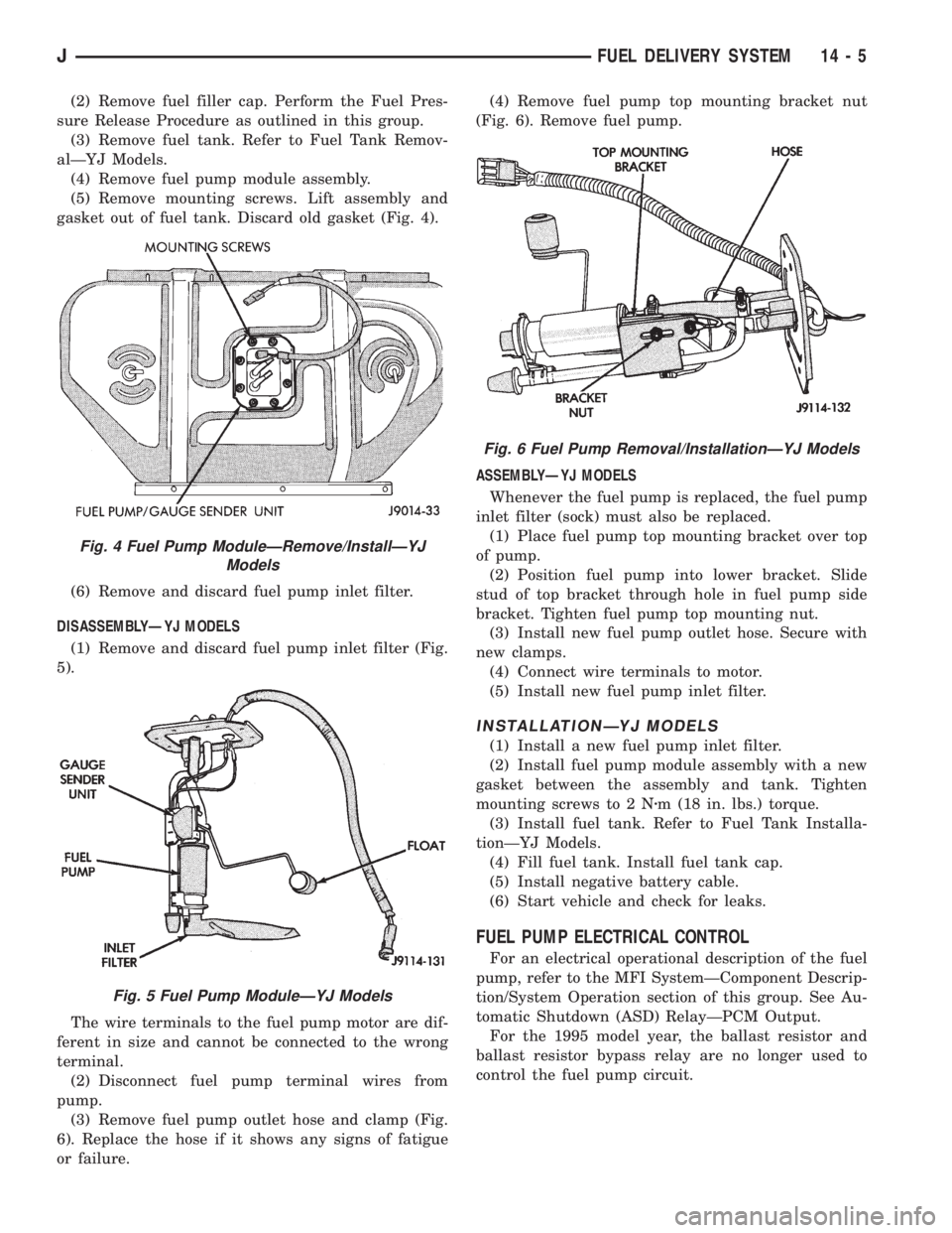
gasket out of fuel tank. Discard old gasket (Fig. 4).
(6) Remove and discard fuel pump inlet filter.
DISASSEMBLYÐYJ MODELS
(1) Remove and discard fuel pump inlet filter (Fig.
5).
The wire terminals to the fuel pump motor are dif-
ferent in size and cannot be connected to the wrong
terminal.
(2) Disconnect fuel pump terminal wires from
pump.
(3) Remove fuel pump outlet hose and clamp (Fig.
6). Replace the hose if it shows any signs of fatigue
or failure.(4) Remove fuel pump top mounting bracket nut
(Fig. 6). Remove fuel pump.
ASSEMBLYÐYJ MODELS
Whenever the fuel pump is replaced, the fuel pump
inlet filter (sock) must also be replaced.
(1) Place fuel pump top mounting bracket over top
of pump.
(2) Position fuel pump into lower bracket. Slide
stud of top bracket through hole in fuel pump side
bracket. Tighten fuel pump top mounting nut.
(3) Install new fuel pump outlet hose. Secure with
new clamps.
(4) Connect wire terminals to motor.
(5) Install new fuel pump inlet filter.
INSTALLATIONÐYJ MODELS
(1) Install a new fuel pump inlet filter.
(2) Install fuel pump module assembly with a new
gasket between the assembly and tank. Tighten
mounting screws to 2 Nzm (18 in. lbs.) torque.
(3) Install fuel tank. Refer to Fuel Tank Installa-
tionÐYJ Models.
(4) Fill fuel tank. Install fuel tank cap.
(5) Install negative battery cable.
(6) Start vehicle and check for leaks.
FUEL PUMP ELECTRICAL CONTROL
For an electrical operational description of the fuel
pump, refer to the MFI SystemÐComponent Descrip-
tion/System Operation section of this group. See Au-
tomatic Shutdown (ASD) RelayÐPCM Output.
For the 1995 model year, the ballast resistor and
ballast resistor bypass relay are no longer used to
control the fuel pump circuit.
Fig. 4 Fuel Pump ModuleÐRemove/InstallÐYJ
Models
Fig. 5 Fuel Pump ModuleÐYJ Models
Fig. 6 Fuel Pump Removal/InstallationÐYJ Models
JFUEL DELIVERY SYSTEM 14 - 5
Page 1415 of 2158

FUEL TANKS
INDEX
page page
Fuel Gauge Sending Unit................... 16
Fuel Tank............................... 13
Fuel Tank Capacities....................... 13
Fuel Tank Filler Tube Cap................... 13Fuel Tank Pressure Relief/Rollover Valve........ 16
General Information....................... 13
Heat Shields............................. 13
No-Lead Fuel Tank Filler Tube................ 13
GENERAL INFORMATION
All XJ and YJ models pass a full 360 degree roll-
over test without fuel leakage. To accomplish this,
fuel and vapor flow controls are required for all fuel
tank connections.
All models are equipped with a pressure relief/roll-
over valve mounted in the top of the fuel tank. The
return line from the fuel pump to the fuel tank con-
tains a one-way check valve.
An evaporative control system prevents raw fuel
vapor from escaping into the atmosphere. Fuel va-
pors from the fuel tank are collected in the EVAP
canister. When the engine is operating, the vapors
are drawn into the intake manifold to be used in
combustion. Refer to Group 25, Emission Control
System for more information.
Inspect all hose/tube connections for completeness.
Be sure that leaks are not present. Replace any hose
that is cracked, scuffed, swelled, has rubbed against
other vehicle components or shows any other sign of
wear that could lead to failure. If it is necessary to
replace a hose, only hose marked EFM/EFI may be
used.
When installing hoses, be sure that they are routed
away from contact with other vehicle components.
The hose clamps used on fuel injected vehicles are
of a special rolled edge construction to prevent the
edge of the clamp from cutting into the hose. Only
these rolled edge type clamps may be used on this
system. Other types of clamps may cut into the hoses
and cause high-pressure fuel leaks.
FUEL TANK CAPACITIES
Refer to the Specifications section at the end of this
group.
NO-LEAD FUEL TANK FILLER TUBE
All vehicles are designed to operate using Unleaded
fuels. The diameter of the opening in the fuel tank
filler neck is sized to only accept unleaded fuel noz-
zles. Gasoline station pumps for unleaded and leaded
fuels have different size nozzles. Leaded fuel nozzles
are larger in diameter than unleaded nozzles. The
fuel tank filler neck opening is also equipped with adeflector, which the smaller unleaded nozzle pushes
back upon entering the filler neck. The deflector will
prevent the larger diameter leaded fuel nozzles from
entering the filler neck and will deflect fuel away
from the filler neck. This happens if filling of the
tank with leaded fuel is attempted.
A label is attached to the instrument panel under
the fuel gauge that reads UNLEADED FUEL ONLY
as a reminder to the driver. A similar label is located
near the fuel tank filler.
FUEL TANK FILLER TUBE CAP
The loss of any fuel or vapor out of the filler neck
is prevented by the use of a safety filler cap. This
will release only under pressure of 10.9 to 13.45 kPa
(1.58 to 1.95 psi). The vacuum release is between .97
and 2.0 kPa (.14 and .29 psi). This cap must be re-
placed by a similar unit if replacement is necessary.
CAUTION: Remove the fuel tank filler tube cap prior
to removing or repairing fuel lines to relieve fuel
tank pressure.
HEAT SHIELDS
The sheet metal heat shields may have to be re-
moved when servicing the fuel tank, fuel lines or va-
por vent line. The heat shields must be installed to
protect the lines and tank from the heat of the ex-
haust system. Refer to Group 11, Exhaust System
and Intake Manifold for proper installation.
FUEL TANK
WARNING: THE FUEL SYSTEM IS UNDER CON-
STANT FUEL PRESSURE (EVEN WITH THE ENGINE
OFF) OF APPROXIMATELY 131-269 KPA (19-39 PSI).
THIS PRESSURE MUST BE RELEASED BEFORE
SERVICING FUEL TANK.
REMOVALÐXJ MODELS
Perform the preceding Fuel System Pressure Re-
lease Procedure.
(1) Disconnect negative battery cable.
JFUEL TANKS 14 - 13
Page 1687 of 2158

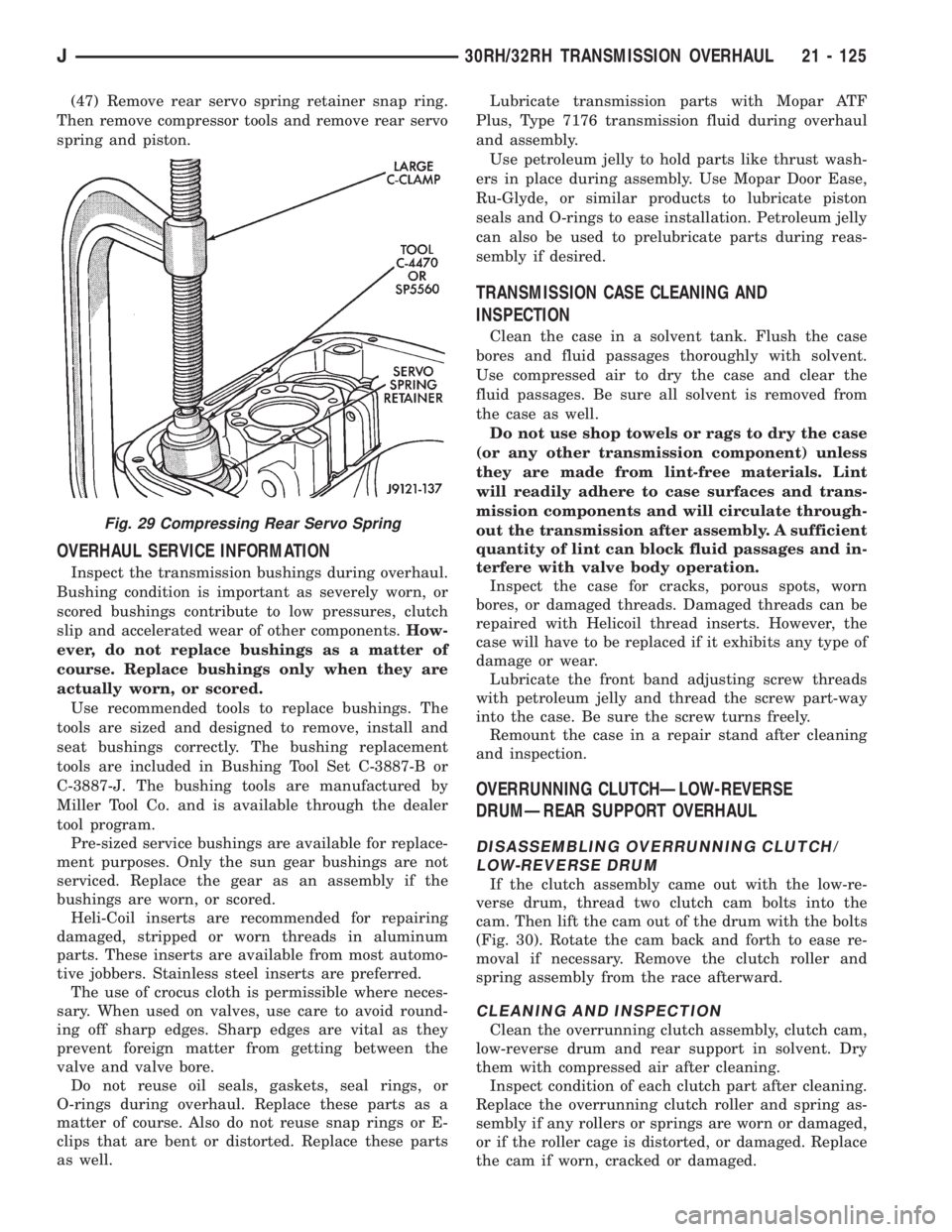
(47) Remove rear servo spring retainer snap ring.
Then remove compressor tools and remove rear servo
spring and piston.
OVERHAUL SERVICE INFORMATION
Inspect the transmission bushings during overhaul.
Bushing condition is important as severely worn, or
scored bushings contribute to low pressures, clutch
slip and accelerated wear of other components.How-
ever, do not replace bushings as a matter of
course. Replace bushings only when they are
actually worn, or scored.
Use recommended tools to replace bushings. The
tools are sized and designed to remove, install and
seat bushings correctly. The bushing replacement
tools are included in Bushing Tool Set C-3887-B or
C-3887-J. The bushing tools are manufactured by
Miller Tool Co. and is available through the dealer
tool program.
Pre-sized service bushings are available for replace-
ment purposes. Only the sun gear bushings are not
serviced. Replace the gear as an assembly if the
bushings are worn, or scored.
Heli-Coil inserts are recommended for repairing
damaged, stripped or worn threads in aluminum
parts. These inserts are available from most automo-
tive jobbers. Stainless steel inserts are preferred.
The use of crocus cloth is permissible where neces-
sary. When used on valves, use care to avoid round-
ing off sharp edges. Sharp edges are vital as they
prevent foreign matter from getting between the
valve and valve bore.
Do not reuse oil seals, gaskets, seal rings, or
O-rings during overhaul. Replace these parts as a
matter of course. Also do not reuse snap rings or E-
clips that are bent or distorted. Replace these parts
as well.Lubricate transmission parts with Mopar ATF
Plus, Type 7176 transmission fluid during overhaul
and assembly.
Use petroleum jelly to hold parts like thrust wash-
ers in place during assembly. Use Mopar Door Ease,
Ru-Glyde, or similar products to lubricate piston
seals and O-rings to ease installation. Petroleum jelly
can also be used to prelubricate parts during reas-
sembly if desired.
TRANSMISSION CASE CLEANING AND
INSPECTION
Clean the case in a solvent tank. Flush the case
bores and fluid passages thoroughly with solvent.
Use compressed air to dry the case and clear the
fluid passages. Be sure all solvent is removed from
the case as well.
Do not use shop towels or rags to dry the case
(or any other transmission component) unless
they are made from lint-free materials. Lint
will readily adhere to case surfaces and trans-
mission components and will circulate through-
out the transmission after assembly. A sufficient
quantity of lint can block fluid passages and in-
terfere with valve body operation.
Inspect the case for cracks, porous spots, worn
bores, or damaged threads. Damaged threads can be
repaired with Helicoil thread inserts. However, the
case will have to be replaced if it exhibits any type of
damage or wear.
Lubricate the front band adjusting screw threads
with petroleum jelly and thread the screw part-way
into the case. Be sure the screw turns freely.
Remount the case in a repair stand after cleaning
and inspection.
OVERRUNNING CLUTCHÐLOW-REVERSE
DRUMÐREAR SUPPORT OVERHAUL
DISASSEMBLING OVERRUNNING CLUTCH/
LOW-REVERSE DRUM
If the clutch assembly came out with the low-re-
verse drum, thread two clutch cam bolts into the
cam. Then lift the cam out of the drum with the bolts
(Fig. 30). Rotate the cam back and forth to ease re-
moval if necessary. Remove the clutch roller and
spring assembly from the race afterward.
CLEANING AND INSPECTION
Clean the overrunning clutch assembly, clutch cam,
low-reverse drum and rear support in solvent. Dry
them with compressed air after cleaning.
Inspect condition of each clutch part after cleaning.
Replace the overrunning clutch roller and spring as-
sembly if any rollers or springs are worn or damaged,
or if the roller cage is distorted, or damaged. Replace
the cam if worn, cracked or damaged.
Fig. 29 Compressing Rear Servo Spring
J30RH/32RH TRANSMISSION OVERHAUL 21 - 125