1995 JEEP YJ length
[x] Cancel search: lengthPage 1824 of 2158
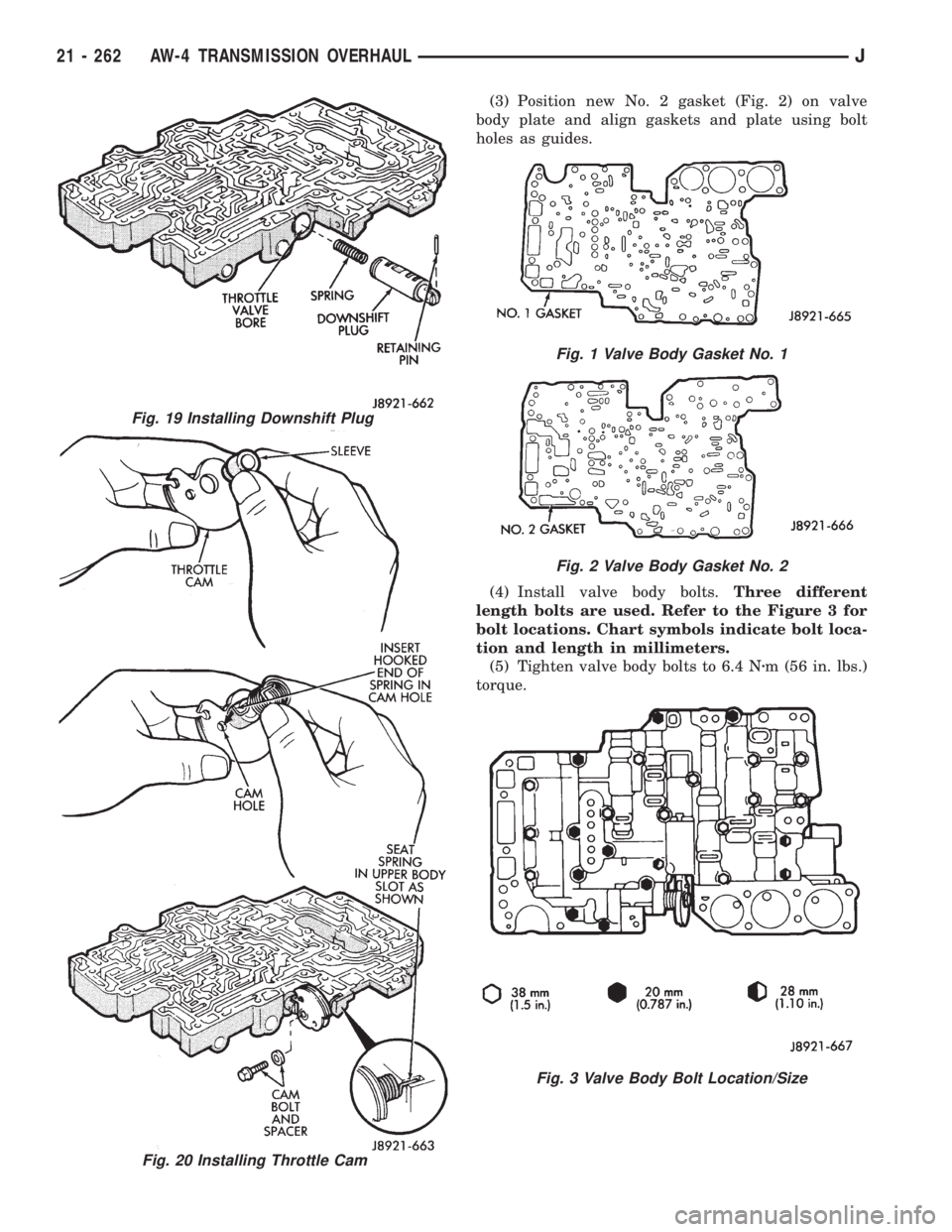
(3) Position new No. 2 gasket (Fig. 2) on valve
body plate and align gaskets and plate using bolt
holes as guides.
(4) Install valve body bolts.Three different
length bolts are used. Refer to the Figure 3 for
bolt locations. Chart symbols indicate bolt loca-
tion and length in millimeters.
(5) Tighten valve body bolts to 6.4 Nzm (56 in. lbs.)
torque.
Fig. 19 Installing Downshift Plug
Fig. 20 Installing Throttle Cam
Fig. 1 Valve Body Gasket No. 1
Fig. 2 Valve Body Gasket No. 2
Fig. 3 Valve Body Bolt Location/Size
21 - 262 AW-4 TRANSMISSION OVERHAULJ
Page 1834 of 2158
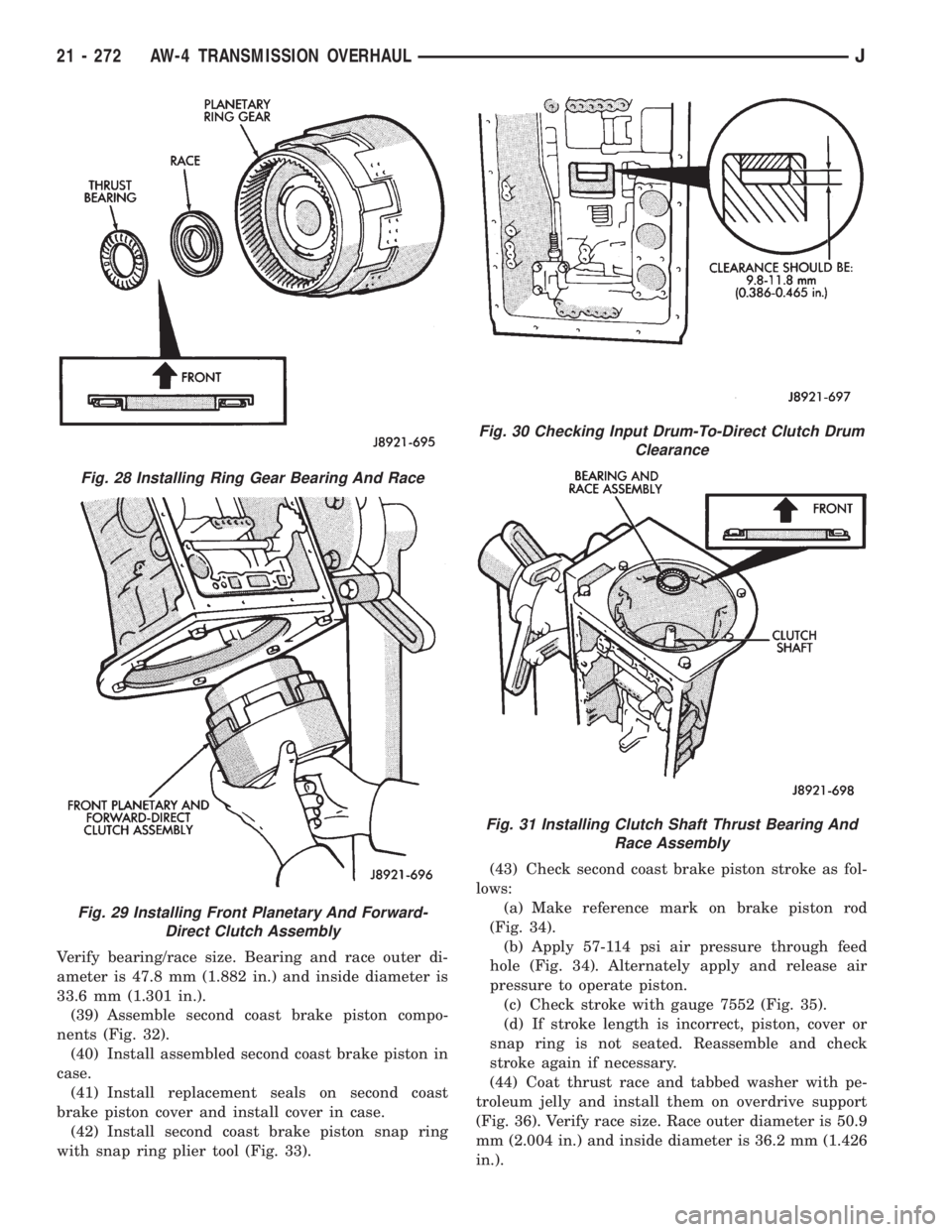
Verify bearing/race size. Bearing and race outer di-
ameter is 47.8 mm (1.882 in.) and inside diameter is
33.6 mm (1.301 in.).
(39) Assemble second coast brake piston compo-
nents (Fig. 32).
(40) Install assembled second coast brake piston in
case.
(41) Install replacement seals on second coast
brake piston cover and install cover in case.
(42) Install second coast brake piston snap ring
with snap ring plier tool (Fig. 33).(43) Check second coast brake piston stroke as fol-
lows:
(a) Make reference mark on brake piston rod
(Fig. 34).
(b) Apply 57-114 psi air pressure through feed
hole (Fig. 34). Alternately apply and release air
pressure to operate piston.
(c) Check stroke with gauge 7552 (Fig. 35).
(d) If stroke length is incorrect, piston, cover or
snap ring is not seated. Reassemble and check
stroke again if necessary.
(44) Coat thrust race and tabbed washer with pe-
troleum jelly and install them on overdrive support
(Fig. 36). Verify race size. Race outer diameter is 50.9
mm (2.004 in.) and inside diameter is 36.2 mm (1.426
in.).
Fig. 28 Installing Ring Gear Bearing And Race
Fig. 29 Installing Front Planetary And Forward-
Direct Clutch Assembly
Fig. 30 Checking Input Drum-To-Direct Clutch Drum
Clearance
Fig. 31 Installing Clutch Shaft Thrust Bearing And
Race Assembly
21 - 272 AW-4 TRANSMISSION OVERHAULJ
Page 1837 of 2158
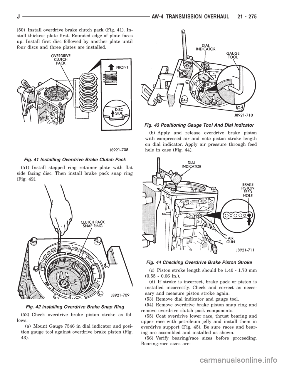
(50) Install overdrive brake clutch pack (Fig. 41). In-
stall thickest plate first. Rounded edge of plate faces
up. Install first disc followed by another plate until
four discs and three plates are installed.
(51) Install stepped ring retainer plate with flat
side facing disc. Then install brake pack snap ring
(Fig. 42).
(52) Check overdrive brake piston stroke as fol-
lows:
(a) Mount Gauge 7546 in dial indicator and posi-
tion gauge tool against overdrive brake piston (Fig.
43).(b) Apply and release overdrive brake piston
with compressed air and note piston stroke length
on dial indicator. Apply air pressure through feed
hole in case (Fig. 44).
(c) Piston stroke length should be 1.40 - 1.70 mm
(0.55 - 0.66 in.).
(d) If stroke is incorrect, brake pack or piston is
installed incorrectly. Check and correct as neces-
sary and measure piston stroke again.
(53) Remove dial indicator and gauge tool.
(54) Remove overdrive brake piston snap ring and
remove overdrive clutch pack components.
(55) Coat overdrive lower race, thrust bearing and
upper race with petroleum jelly and install them in
overdrive support (Fig. 45). Be sure races and bear-
ing are assembled and installed as shown.
(56) Verify bearing/race sizes before proceeding.
Bearing-race sizes are:
Fig. 41 Installing Overdrive Brake Clutch Pack
Fig. 42 installing Overdrive Brake Snap Ring
Fig. 43 Positioning Gauge Tool And Dial Indicator
Fig. 44 Checking Overdrive Brake Piston Stroke
JAW-4 TRANSMISSION OVERHAUL 21 - 275
Page 1929 of 2158
(2) Install the hinge nuts on the studs. Tighten the
restraint cable nut to 4 Nzm (38 in-lbs) torque.
Tighten the remaining nuts to 9 Nzm (77 in-lbs)
torque.
If a replacement hinge seal is being installed,
position it around the hinge arm, force it
against the hinge base.
(3) Position the hinge seal around the hinge arm
and on hinge base.
(4) Install the hood.
(5) Adjust the hood as necessary.
HOOD LATCH REPLACEMENTÐXJ
REMOVAL
(1) Remove the screw that attaches the latch to the
hood inner panel (Fig. 15).
(2) Disconnect the latch from the hood and latch
connecting rod. Remove the latch from the hood.
INSTALLATION
(1) Connect the latch to the latch connecting rod
and position it on the hood inner panel.
(2) Install the screw that attaches the latch to the
hood inner panel.
(3) Tighten the screw to 9 Nzm (77 in-lbs) torque.
(4) Test the operation of the latch release cable and
latch.
HOOD LATCH STRIKER REPLACEMENTÐXJ
REMOVE
(1) Remove the grille opening panel (GOP).
(2) Remove the screws that attach the striker to
the radiator baffle (Fig. 19).
(3) Remove the striker and shims from the baffle.
INSTALLATION
(1) Position the shims and striker on the radiator
baffle and install the screws.
(2) Tighten the screws to 21 Nzm (15 ft-lbs) torque.
(3) Test the striker/hood alignment by opening and
closing the hood several times. Adjust the striker, if
necessary.
LATCH RELEASE CABLE REPLACEMENTÐXJ
REMOVAL
(1) Drill out the bellcrank to hood rivet heads and
remove the rivets (Fig. 14).
(2) Disconnect the bellcrank from the latch rod and
the latch release cable. Remove the bellcrank from
the hood.
(3) Disconnect the latch release cable from the
clips on the hood.
(4) Remove the left cowl side trim panel.
(5) Remove the cable bracket screws from the cowl
side panel.(6) Pull the cable through the dash panel and re-
move it from under the instrument panel.
INSTALLATION
(1) Insert the replacement cable end through the
hole in the dash panel into the engine compartment.
(2) Pull the cable forward and seat the grommet in
the dash panel.
(3) Position the cable bracket on the cowl side
panel and install the screws. Tighten the screws to
13 Nzm (111 in-lbs) torque.
(4) Install the left cowl side trim panel.
(5) Connect the cable and latch rod to the
bellcrank.
(6) Position the bellcrank on the hood and install
the rivets.
(7) Attach the cable to the clips.
(8) Test release the cable for proper operation.
SAFETY LATCH STRIKER REPLACEMENTÐXJ
REMOVAL
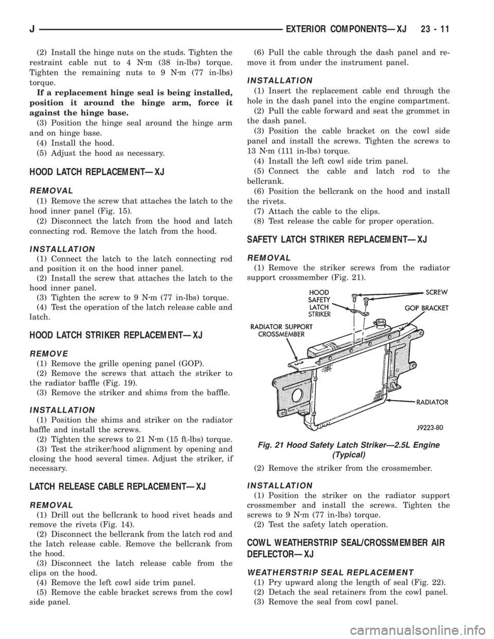
(1) Remove the striker screws from the radiator
support crossmember (Fig. 21).
(2) Remove the striker from the crossmember.
INSTALLATION
(1) Position the striker on the radiator support
crossmember and install the screws. Tighten the
screws to 9 Nzm (77 in-lbs) torque.
(2) Test the safety latch operation.
COWL WEATHERSTRIP SEAL/CROSSMEMBER AIR
DEFLECTORÐXJ
WEATHERSTRIP SEAL REPLACEMENT
(1) Pry upward along the length of seal (Fig. 22).
(2) Detach the seal retainers from the cowl panel.
(3) Remove the seal from cowl panel.
Fig. 21 Hood Safety Latch StrikerÐ2.5L Engine
(Typical)
JEXTERIOR COMPONENTSÐXJ 23 - 11
Page 1939 of 2158
(4) If the original molding will be installed, also re-
move all adhesive from it.
INSTALLATION
(1) Install 3M 06379 double-sided tape on the
molding.
(2) For vertical alignment, use masking tape or a
string as reference.
(3) Remove the backing from the tape, align the
molding and position it on the body panel.
(4) Press the molding onto the body panel with a
roller or hand pressure.
BODY STRIPES/DECALSÐXJ
SERVICE INFORMATION
XJ body stripes and decals are weather resistant
tape with a adhesive backing.
REPAIR
Small nicks, scratches and other surface marks in
a body stripe/decal can be touched-up with paint.
To eliminate blisters and air bubbles in a body
stripe/decal, pierce them with a needle or pin.
A heat gun can also be used to remove small wrin-
kles in a stripe/decal.
REQUIREMENTS
Body stripe/decal replacement requires that the
metal repair and paint refinish be completed first.
The work area temperature should be between
18ÉC (65ÉF) and 32ÉC (90ÉF).A tape stripe/decal
should not be replaced if the work area temper-
ature is less than 18ÉC (65ÉF).
The following equipment and material are neces-
sary for removal and installation:
²Commercial tape stripe/decal removal solution.
²Commercial adhesive removal solution.
²Liquid dish detergent (for the wetting solution).
²Mixture of wetting solution.
²Commercial wax and silicone removal solution.
²Isopropyl (rubbing) alcohol.
²Small squeegee (plastic or hard rubber).
²Water bucket and sponge.
²Clean wiping rags or paper towels.
²Heat gun (or infra-red heat bulb).
²Wax pencil.
²
Sharp knife, single edge razor blade or X-acto knife.
²Pair of scissors.
²Needle or pin.
The use of a wetting solution aids the installation of a
tape stripe/decal on a painted panel. Prepare the wet-
ting solution by mixing two or three teaspoons of dish
detergent with 1 gallon of water.Do not use soap.
Too much detergent will reduce the effective-
ness of the mixture.
REMOVAL
(1) Clean the repaired surface, adjacent panels and
door the openings as necessary.
(2) Start at one end of the tape stripe/decal and
apply heat with a heat gun. Slowly peel the stripe/
decal from the panel by pulling it back.Do not pull
the tape stripe/decal outward from panel.
WARNING: USE TAPE STRIPE/DECAL REMOVAL
SOLUTION IN A WELL-VENTILATED AREA ONLY.
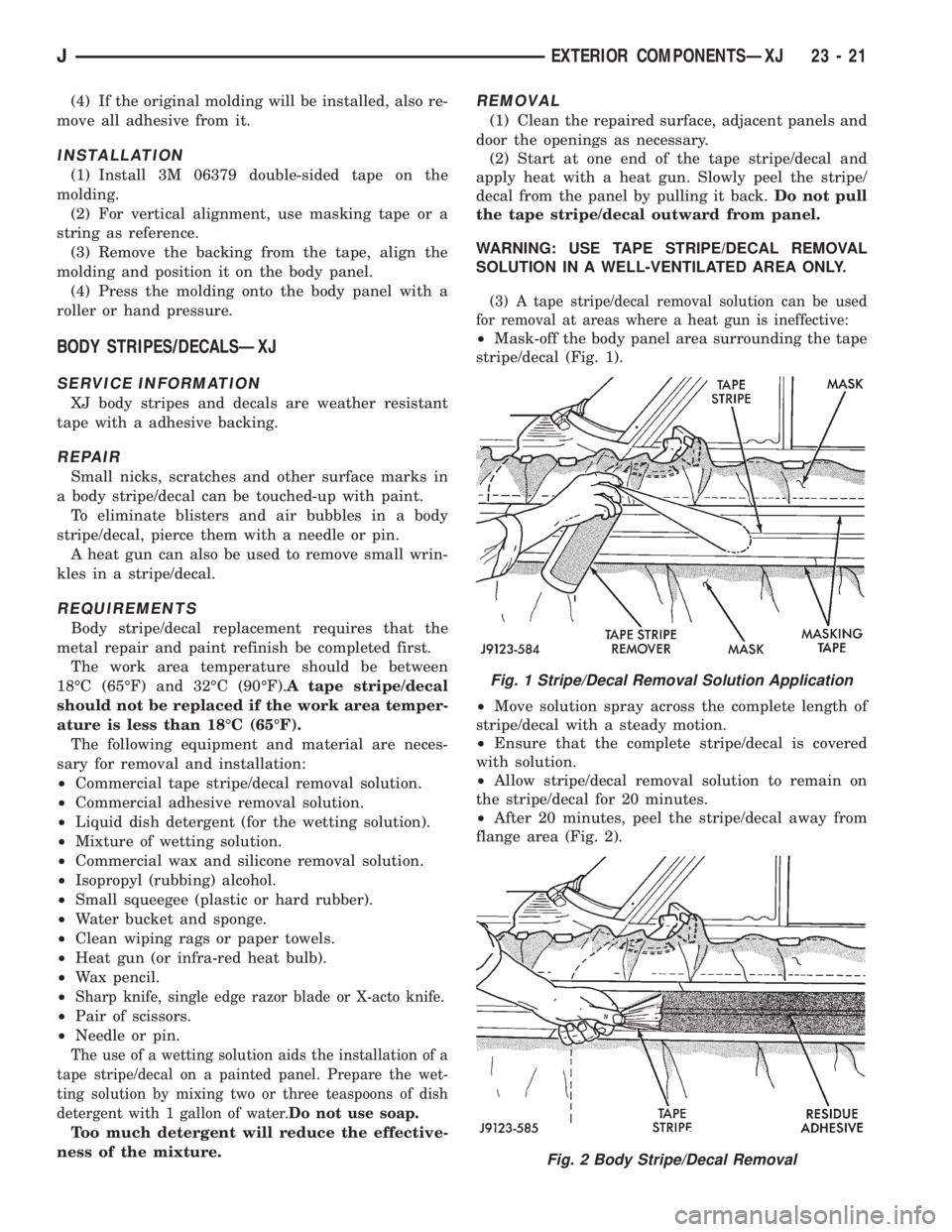
(3) A tape stripe/decal removal solution can be used
for removal at areas where a heat gun is ineffective:
²Mask-off the body panel area surrounding the tape
stripe/decal (Fig. 1).
²Move solution spray across the complete length of
stripe/decal with a steady motion.
²Ensure that the complete stripe/decal is covered
with solution.
²Allow stripe/decal removal solution to remain on
the stripe/decal for 20 minutes.
²After 20 minutes, peel the stripe/decal away from
flange area (Fig. 2).
Fig. 1 Stripe/Decal Removal Solution Application
Fig. 2 Body Stripe/Decal Removal
JEXTERIOR COMPONENTSÐXJ 23 - 21
Page 1940 of 2158
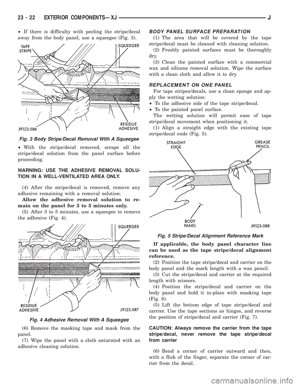
²If there is difficulty with peeling the stripe/decal
away from the body panel, use a squeegee (Fig. 3).
²With the stripe/decal removed, scrape all the
stripe/decal solution from the panel surface before
proceeding.
WARNING: USE THE ADHESIVE REMOVAL SOLU-
TION IN A WELL-VENTILATED AREA ONLY.
(4) After the stripe/decal is removed, remove any
adhesive remaining with a removal solution.
Allow the adhesive removal solution to re-
main on the panel for 3 to 5 minutes only.
(5) After 3 to 5 minutes, use a squeegee to remove
the adhesive (Fig. 4).
(6) Remove the masking tape and mask from the
panel.
(7) Wipe the panel with a cloth saturated with an
adhesive cleaning solution.BODY PANEL SURFACE PREPARATION
(1) The area that will be covered by the tape
stripe/decal must be cleaned with cleaning solution.
(2) Freshly painted surfaces must be thoroughly
dry.
(3) Clean the painted surface with a commercial
wax and silicone removal solution. Wipe the surface
with a clean cloth and allow it to dry.
REPLACEMENT ON ONE PANEL
For tape stripes/decals, use a clean sponge and ap-
ply the wetting solution:
²To the adhesive side of the tape stripe/decal.
²To the painted panel surface.
The wetting solution will permit ease of tape
stripe/decal movement when positioning it.
(1) Align a straight edge with the existing tape
stripe/decal ends (Fig. 5).
If applicable, the body panel character line
can be used as the tape stripe/decal alignment
reference.
(2) Position the tape stripe/decal and carrier on the
body panel and the mark length with a wax pencil.
(3) Cut the stripe/decal and carrier at the required
length with scissors.
(4) Position the stripe/decal and carrier on the
body panel and hold it in-place with masking tape
(Fig. 6).
(5) Lift the bottom edge of tape stripe/decal and
carrier. Use the tape sections as hinges, and reverse
the position of stripe/decal and carrier (Fig. 7).
CAUTION: Always remove the carrier from the tape
stripe/decal, never remove the tape stripe/decal
from carrier
(6) Bend a corner of carrier outward and then,
with a flick of the finger, separate the corner of car-
rier from the decal.
Fig. 3 Body Stripe/Decal Removal With A Squeegee
Fig. 4 Adhesive Removal With A Squeegee
Fig. 5 Stripe/Decal Alignment Reference Mark
23 - 22 EXTERIOR COMPONENTSÐXJJ
Page 1987 of 2158
(5) Start the hot knife blade (special tool C-4386)
between the glass and the urethane. Next, cut the
adhesive as close to the glass edge as possible (Fig.
1). Allow as much adhesive to remain on the pinch-
weld flange as possible.For best cutting results,
clean the knife blade frequently with steel wool
while the blade is hot.
(6) Remove the windshield glass from the body
opening.
(7) After the hot knife blade has cooled, clean the
blade with solvent and a clean cloth.
INSTALLATIONÐSHORT METHOD
Normally, after a replacement windshield glass is
installed, the rearview mirror bracket also requires
installation.Do not install the bracket until after
the windshield glass installation is completed.
(1) Inspect the windshield opening pinchweld
flanges. Prime any bare spots with urethane primer.
Allow a minimum of 18 minutes for dry time.
(2) Inspect urethane bead for high spots. Level
bead by shaving off high spots with a razor knife.
(3) Clean the outer edge of windshield glass with
naphtha or an equivalent product.
(4) Prime outer perimeter of interior side of glass 16
mm (5/8 inch) from edge. Use a wipe-off type urethane
primer and wipe glass dry after primer application.
NOTE: The reveal molding has an adhesive applied
to the windshield contact surface to help secure the
molding to the windshield during the installation
procedure.
(5) Apply the molding to the windshield:
²With the molding at room temperature, press the
molding onto the windshield corners.
²From corner to corner, work the molding to the
center of each side. (Some stretching of the mold-
ing may be required during this procedure.)(6) Place the glass on the pinchweld flanges and
inspect for gaps in the urethane. Gaps in excess of 3
mm (1/8 inch) must be filled with urethane.
(7) Adjust windshield glass position until it is
aligned with the flanges and adhesive. Next, make
alignment marks on the glass and body.
(8) Remove the windshield glass and position it on
a flat surface.
CAUTION: Avoid spilling or dripping primer on
painted surfaces. Clean spills or drips immediately.
The primer will damage the paint if it remains on
the surface for any length of time.
(9) If the replacement windshield glass does not
have blackout primer:
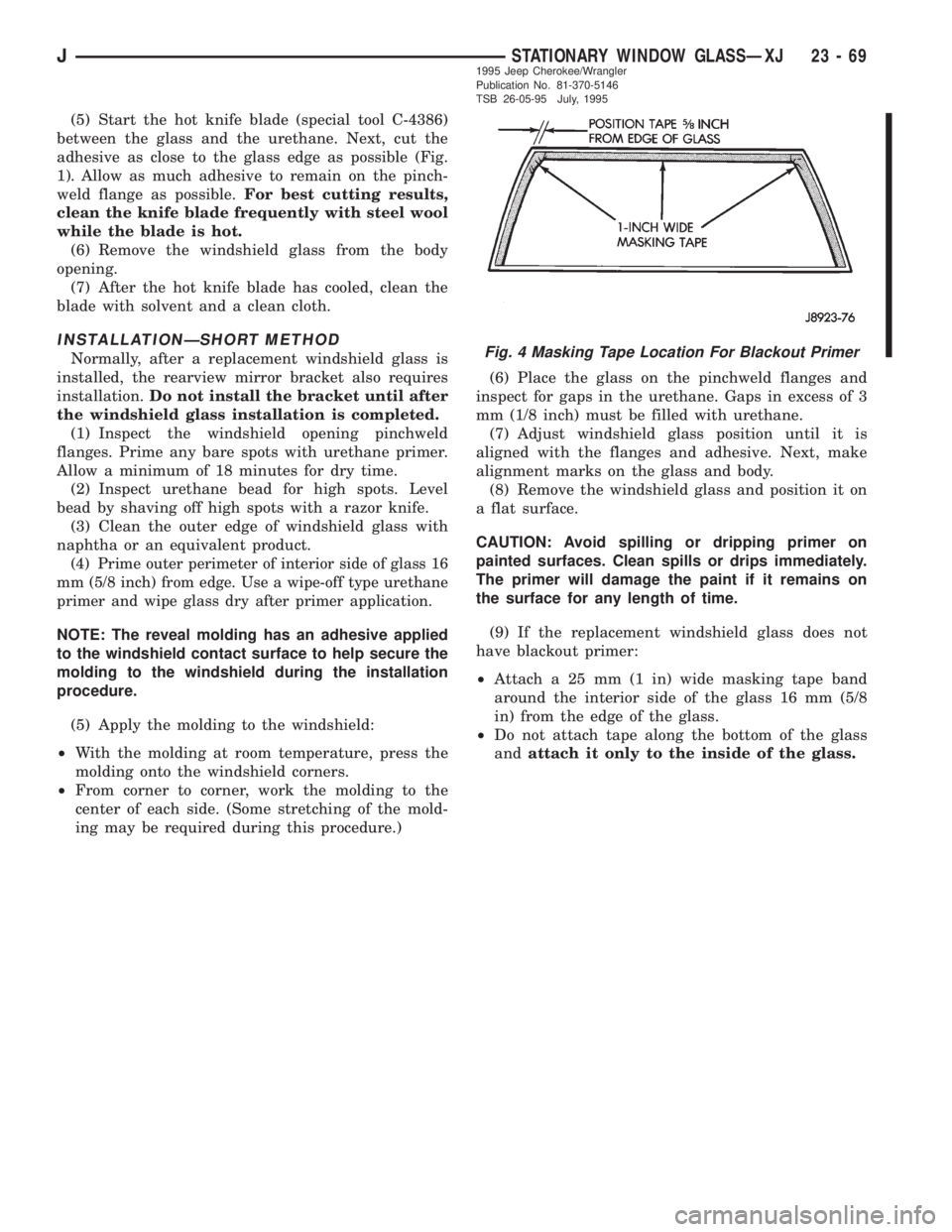
²Attach a 25 mm (1 in) wide masking tape band
around the interior side of the glass 16 mm (5/8
in) from the edge of the glass.
²Do not attach tape along the bottom of the glass
andattach it only to the inside of the glass.
Fig. 4 Masking Tape Location For Blackout Primer
JSTATIONARY WINDOW GLASSÐXJ 23 - 691995 Jeep Cherokee/Wrangler
Publication No. 81-370-5146
TSB 26-05-95 July, 1995
Page 1992 of 2158
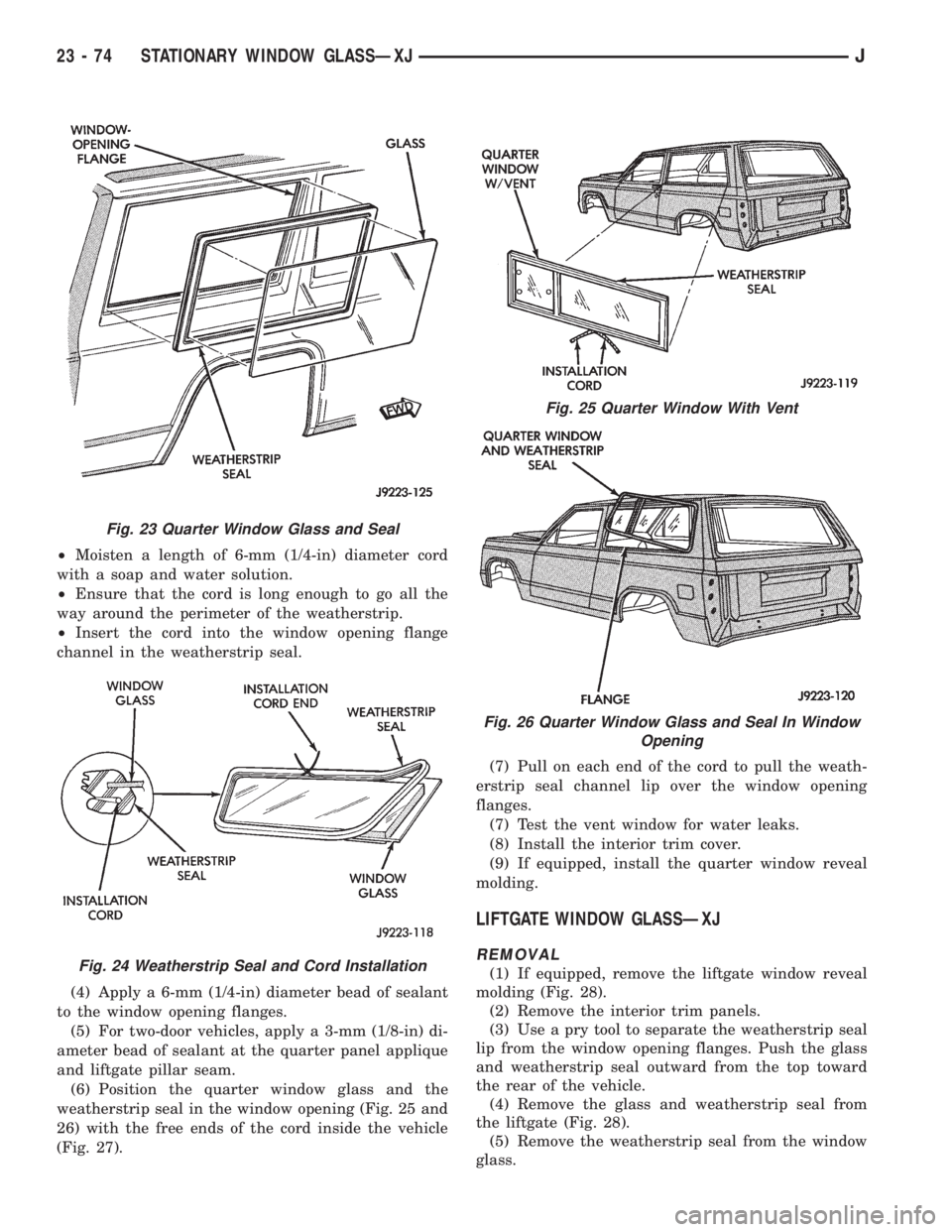
²Moisten a length of 6-mm (1/4-in) diameter cord
with a soap and water solution.
²Ensure that the cord is long enough to go all the
way around the perimeter of the weatherstrip.
²Insert the cord into the window opening flange
channel in the weatherstrip seal.
(4) Apply a 6-mm (1/4-in) diameter bead of sealant
to the window opening flanges.
(5) For two-door vehicles, apply a 3-mm (1/8-in) di-
ameter bead of sealant at the quarter panel applique
and liftgate pillar seam.
(6) Position the quarter window glass and the
weatherstrip seal in the window opening (Fig. 25 and
26) with the free ends of the cord inside the vehicle
(Fig. 27).(7) Pull on each end of the cord to pull the weath-
erstrip seal channel lip over the window opening
flanges.
(7) Test the vent window for water leaks.
(8) Install the interior trim cover.
(9) If equipped, install the quarter window reveal
molding.
LIFTGATE WINDOW GLASSÐXJ
REMOVAL
(1) If equipped, remove the liftgate window reveal
molding (Fig. 28).
(2) Remove the interior trim panels.
(3) Use a pry tool to separate the weatherstrip seal
lip from the window opening flanges. Push the glass
and weatherstrip seal outward from the top toward
the rear of the vehicle.
(4) Remove the glass and weatherstrip seal from
the liftgate (Fig. 28).
(5) Remove the weatherstrip seal from the window
glass.
Fig. 23 Quarter Window Glass and Seal
Fig. 24 Weatherstrip Seal and Cord Installation
Fig. 25 Quarter Window With Vent
Fig. 26 Quarter Window Glass and Seal In Window
Opening
23 - 74 STATIONARY WINDOW GLASSÐXJJ