Page 1795 of 2158
Fig. 2 Positioning Drum And Support On Wood
Blocks
Fig. 3 Checking Forward Clutch Piston Stroke
Length
Fig. 4 Removing Retainer And Clutch Pack
Fig. 5 Removing Cushion Plate
JAW-4 TRANSMISSION OVERHAUL 21 - 233
Page 1796 of 2158
(11) Remove spring compressor tool and piston re-
turn springs.
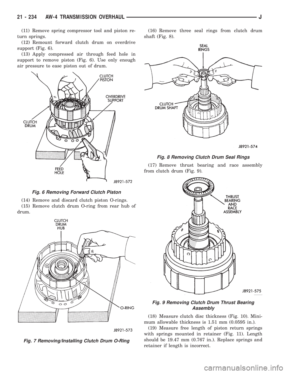
(12) Remount forward clutch drum on overdrive
support (Fig. 6).
(13) Apply compressed air through feed hole in
support to remove piston (Fig. 6). Use only enough
air pressure to ease piston out of drum.
(14) Remove and discard clutch piston O-rings.
(15) Remove clutch drum O-ring from rear hub of
drum.(16) Remove three seal rings from clutch drum
shaft (Fig. 8).
(17) Remove thrust bearing and race assembly
from clutch drum (Fig. 9).
(18) Measure clutch disc thickness (Fig. 10). Mini-
mum allowable thickness is 1.51 mm (0.0595 in.).
(19) Measure free length of piston return springs
with springs mounted in retainer (Fig. 11). Length
should be 19.47 mm (0.767 in.). Replace springs and
retainer if length is incorrect.
Fig. 6 Removing Forward Clutch Piston
Fig. 7 Removing/Installing Clutch Drum O-Ring
Fig. 8 Removing Clutch Drum Seal Rings
Fig. 9 Removing Clutch Drum Thrust Bearing
Assembly
21 - 234 AW-4 TRANSMISSION OVERHAULJ
Page 1797 of 2158
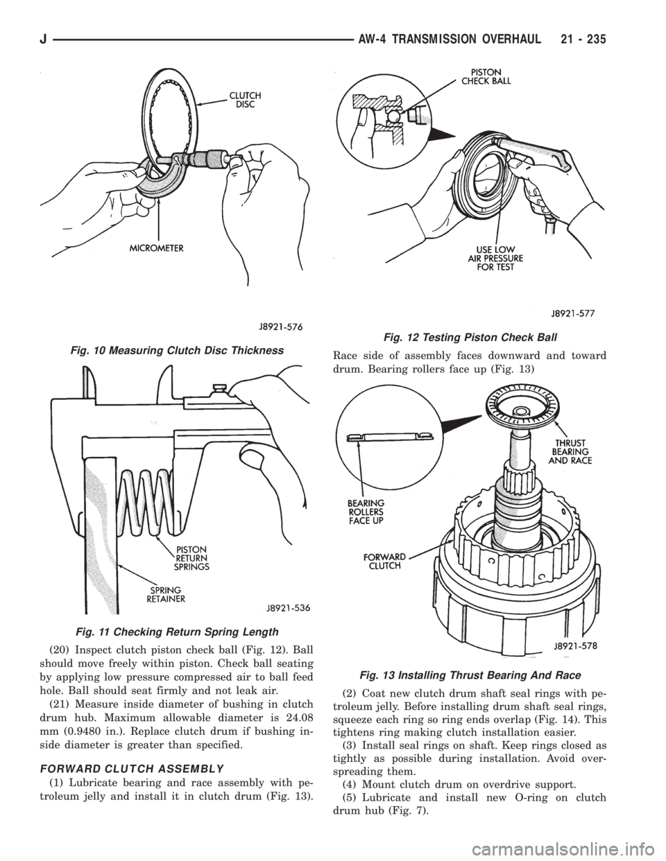
(20) Inspect clutch piston check ball (Fig. 12). Ball
should move freely within piston. Check ball seating
by applying low pressure compressed air to ball feed
hole. Ball should seat firmly and not leak air.
(21) Measure inside diameter of bushing in clutch
drum hub. Maximum allowable diameter is 24.08
mm (0.9480 in.). Replace clutch drum if bushing in-
side diameter is greater than specified.
FORWARD CLUTCH ASSEMBLY
(1) Lubricate bearing and race assembly with pe-
troleum jelly and install it in clutch drum (Fig. 13).Race side of assembly faces downward and toward
drum. Bearing rollers face up (Fig. 13)
(2) Coat new clutch drum shaft seal rings with pe-
troleum jelly. Before installing drum shaft seal rings,
squeeze each ring so ring ends overlap (Fig. 14). This
tightens ring making clutch installation easier.
(3) Install seal rings on shaft. Keep rings closed as
tightly as possible during installation. Avoid over-
spreading them.
(4) Mount clutch drum on overdrive support.
(5) Lubricate and install new O-ring on clutch
drum hub (Fig. 7).
Fig. 10 Measuring Clutch Disc Thickness
Fig. 11 Checking Return Spring Length
Fig. 12 Testing Piston Check Ball
Fig. 13 Installing Thrust Bearing And Race
JAW-4 TRANSMISSION OVERHAUL 21 - 235
Page 1798 of 2158
(6) Lubricate and install new O-rings on clutch pis-
ton and install piston in drum.
(7) Install piston return springs.
(8) Compress piston return springs with Tool 7538
and shop press and install piston snap ring. Be sure
snap ring end gap is not aligned with any notches in
drum.
(9) Install cushion plate in drum. Concave side of
plate faces downward (Fig. 5).
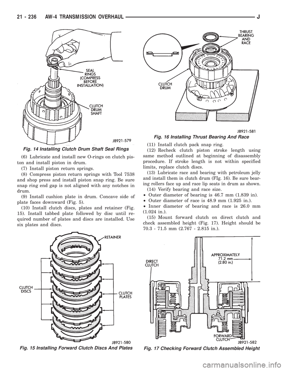
(10) Install clutch discs, plates and retainer (Fig.
15). Install tabbed plate followed by disc until re-
quired number of plates and discs are installed. Use
six plates and discs.(11) Install clutch pack snap ring.
(12) Recheck clutch piston stroke length using
same method outlined at beginning of disassembly
procedure. If stroke length is not within specified
limits, replace clutch discs.
(13) Lubricate race and bearing with petroleum jelly
and install them in clutch drum (FIg. 16). Be sure bear-
ing rollers face up and race lip seats in drum as shown.
(14) Verify bearing and race size.
²Outer diameter of bearing is 46.7 mm (1.839 in).
²Outer diameter of race is 48.9 mm (1.925 in.).
²Inner diameter of bearing and race is 26.0 mm
(1.024 in.).
(15) Mount forward clutch on direct clutch and
check assembled height (Fig. 17). Height should be
70.3 - 71.5 mm (2.767 - 2.815 in.).
Fig. 15 Installing Forward Clutch Discs And Plates
Fig. 16 Installing Thrust Bearing And Race
Fig. 17 Checking Forward Clutch Assembled Height
Fig. 14 Installing Clutch Drum Shaft Seal Rings
21 - 236 AW-4 TRANSMISSION OVERHAULJ
Page 1804 of 2158
(4) Compress piston return springs with shop press
and tool 7538. Then remove piston snap ring (Fig. 4).
(5) Remove compressor tool and remove spring re-
tainer and return springs.
(6) Remove second brake piston and sleeve from
drum with compressed air (Fig. 5). Use only enough
air pressure to ease piston out of drum.(7) Remove and discard brake piston O-rings.
(8) Measure free length of piston return springs
with springs mounted in retainer (Fig. 6). Length
should be approximately 16.05 mm (0.632 in.). Re-
place return springs if length is less than specified.
Fig. 4 Removing/Installing Second Brake Piston
Snap Ring
Fig. 5 Removing/Installing Piston And Sleeve
Fig. 6 Measuring Second Brake Piston Return
Springs
21 - 242 AW-4 TRANSMISSION OVERHAULJ
Page 1810 of 2158
(4) Remove Tool 7539 and remove piston return
springs.
(5) Remove No. 2 first-reverse brake piston with
compressed air. Apply air through same transmission
feed hole used for checking piston operation.
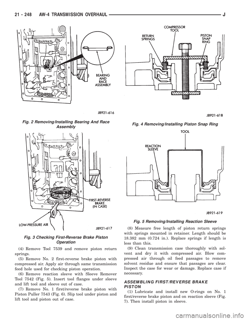
(6) Remove reaction sleeve with Sleeve Remover
Tool 7542 (Fig. 5). Insert tool flanges under sleeve
and lift tool and sleeve out of case.
(7) Remove No. 1 first/reverse brake piston with
Piston Puller 7543 (Fig. 6). Slip tool under piston and
lift tool and piston out of case.(8) Measure free length of piston return springs
with springs mounted in retainer. Length should be
18.382 mm (0.724 in.). Replace springs if length is
less than this.
(9) Clean transmission case thoroughly with sol-
vent and dry it with compressed air. Blow com-
pressed air through oil feed passages to remove
solvent residue and ensure that passages are clear.
Inspect the case for wear or damage. Replace case if
necessary.
ASSEMBLING FIRST/REVERSE BRAKE
PISTON
(1) Lubricate and install new O-rings on No. 1
first/reverse brake piston and on reaction sleeve (Fig.
7). Then install piston in sleeve.
Fig. 2 Removing/Installing Bearing And Race
Assembly
Fig. 3 Checking First-Reverse Brake Piston
Operation
Fig. 4 Removing/Installing Piston Snap Ring
Fig. 5 Removing/Installing Reaction Sleeve
21 - 248 AW-4 TRANSMISSION OVERHAULJ
Page 1816 of 2158
use shop towels or rags. Lint or foreign material from
towels or rags can interfere with valve operation.
(13) Inspect condition of lower body components.
Replace lower body if any bores are scored or cor-
roded. Replace valves, plugs or sleeves that are
scored or worn. Replace oil strainers if cut, torn or
damaged in any way.
(14) Inspect valve body springs. Replace any spring
having rusted, distorted, or collapsed coils. Measure
length of each valve body spring. Replace any spring
if free length is less than length specified in following
chart (Fig. 11).
LOWER BODY ASSEMBLY
(1) Lubricate lower body components with auto-
matic transmission fluid.
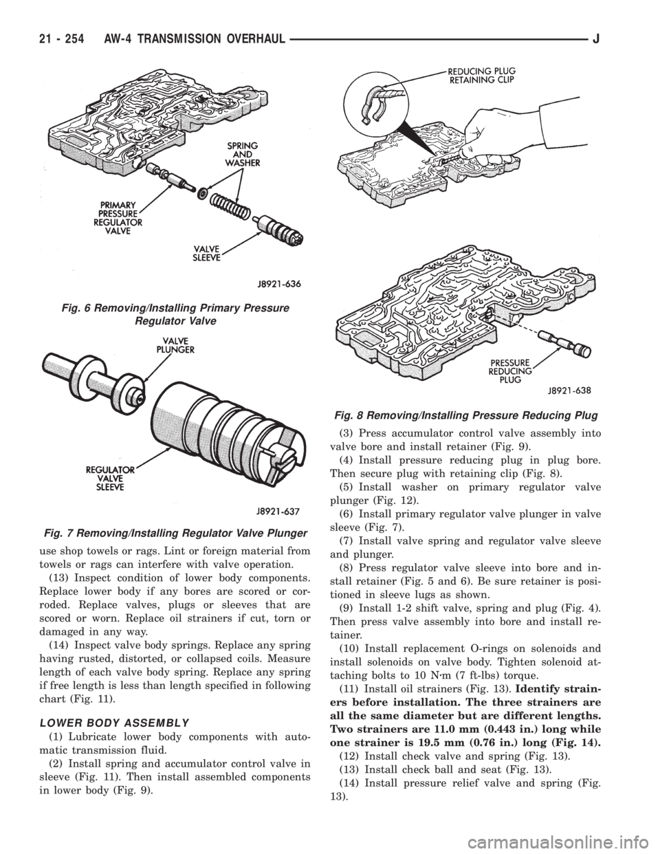
(2) Install spring and accumulator control valve in
sleeve (Fig. 11). Then install assembled components
in lower body (Fig. 9).(3) Press accumulator control valve assembly into
valve bore and install retainer (Fig. 9).
(4) Install pressure reducing plug in plug bore.
Then secure plug with retaining clip (Fig. 8).
(5) Install washer on primary regulator valve
plunger (Fig. 12).
(6) Install primary regulator valve plunger in valve
sleeve (Fig. 7).
(7) Install valve spring and regulator valve sleeve
and plunger.
(8) Press regulator valve sleeve into bore and in-
stall retainer (Fig. 5 and 6). Be sure retainer is posi-
tioned in sleeve lugs as shown.
(9) Install 1-2 shift valve, spring and plug (Fig. 4).
Then press valve assembly into bore and install re-
tainer.
(10) Install replacement O-rings on solenoids and
install solenoids on valve body. Tighten solenoid at-
taching bolts to 10 Nzm (7 ft-lbs) torque.
(11) Install oil strainers (Fig. 13).Identify strain-
ers before installation. The three strainers are
all the same diameter but are different lengths.
Two strainers are 11.0 mm (0.443 in.) long while
one strainer is 19.5 mm (0.76 in.) long (Fig. 14).
(12) Install check valve and spring (Fig. 13).
(13) Install check ball and seat (Fig. 13).
(14) Install pressure relief valve and spring (Fig.
13).
Fig. 6 Removing/Installing Primary Pressure
Regulator Valve
Fig. 7 Removing/Installing Regulator Valve Plunger
Fig. 8 Removing/Installing Pressure Reducing Plug
21 - 254 AW-4 TRANSMISSION OVERHAULJ
Page 1822 of 2158
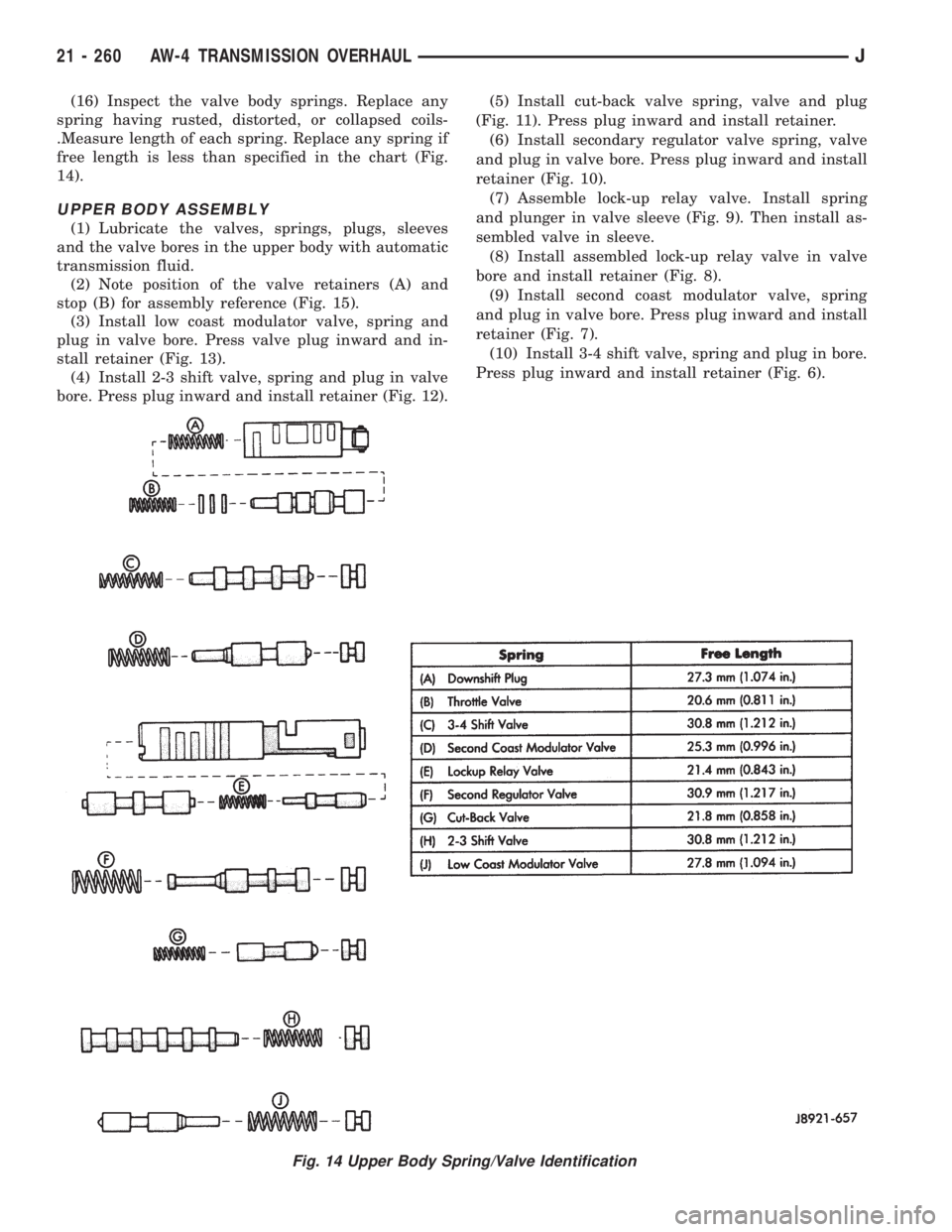
(16) Inspect the valve body springs. Replace any
spring having rusted, distorted, or collapsed coils-
.Measure length of each spring. Replace any spring if
free length is less than specified in the chart (Fig.
14).
UPPER BODY ASSEMBLY
(1) Lubricate the valves, springs, plugs, sleeves
and the valve bores in the upper body with automatic
transmission fluid.
(2) Note position of the valve retainers (A) and
stop (B) for assembly reference (Fig. 15).
(3) Install low coast modulator valve, spring and
plug in valve bore. Press valve plug inward and in-
stall retainer (Fig. 13).
(4) Install 2-3 shift valve, spring and plug in valve
bore. Press plug inward and install retainer (Fig. 12).(5) Install cut-back valve spring, valve and plug
(Fig. 11). Press plug inward and install retainer.
(6) Install secondary regulator valve spring, valve
and plug in valve bore. Press plug inward and install
retainer (Fig. 10).
(7) Assemble lock-up relay valve. Install spring
and plunger in valve sleeve (Fig. 9). Then install as-
sembled valve in sleeve.
(8) Install assembled lock-up relay valve in valve
bore and install retainer (Fig. 8).
(9) Install second coast modulator valve, spring
and plug in valve bore. Press plug inward and install
retainer (Fig. 7).
(10) Install 3-4 shift valve, spring and plug in bore.
Press plug inward and install retainer (Fig. 6).
Fig. 14 Upper Body Spring/Valve Identification
21 - 260 AW-4 TRANSMISSION OVERHAULJ