1995 JEEP YJ roof
[x] Cancel search: roofPage 317 of 2158

OVERHEAD CONSOLE
CONTENTS
page page
DIAGNOSIS............................. 2
GENERAL INFORMATION.................. 1SERVICE PROCEDURES................... 5
GENERAL INFORMATION
An overhead console featuring an electronic com-
pass and thermometer is an available option for XJ
(Cherokee) models. Following are general descrip-
tions of major components used in the overhead con-
sole. Refer to Group 8W - Wiring Diagrams for
complete circuit descriptions and diagrams.
COMPASS
The compass will display the direction in which the
vehicle is pointed using the eight major compass
headings (Examples: north is N, northeast is NE). It
does not display the headings in actual degrees. The
display is turned on or off using the COMP/TEMP
button to the left of the display.
The self-calibrating compass unit requires no ad-
justing in normal use. The only calibration that may
prove necessary is to drive the vehicle in 3 complete
circles, on level ground, in not less than 48 seconds.
This will reorient the unit to its vehicle.
The unit also will compensate for magnetism the
body of the vehicle may acquire during normal use.
However, avoid placing anything magnetic directly on
the roof of the vehicle. Magnetic mounts for an an-
tenna, a repair order hat or a funeral procession flag
can exceed the compensating ability of the compass
unit if placed on the roof panel. Magnetic bit drivers
used on the fasteners that hold the assembly to the
roof header can also affect compass operation.
If the vehicle roof should become magnetized, the
demagnetizing and calibration procedures may be re-
quired to restore proper operation.
THERMOMETER
The thermometer displays the outside ambient
temperature. The temperature displayed can be
changed from Fahrenheit to Celsius using the US/
METRIC button. The displayed temperature is not
an instant reading of conditions, but an average tem-
perature. It may take the unit several minutes to re-
act to a major temperature change such as driving
out of a heated garage into winter temperatures.
When the ignition switch is turned OFF, the lastdisplayed temperature reading stays in memory.
When the ignition switch is turned ON again, the
thermometer will display the memory temperature
for one minute; then update the display to the cur-
rent average temperature reading within five min-
utes.
READING AND COURTESY LAMPS
All reading and courtesy lamps in the overhead
console are activated by the door jamb switches.
When all doors and the liftgate are closed, the lamps
can be individually activated by depressing the corre-
sponding lens. When a door and/or the liftgate is
open, depressing the lamp lens switches will not turn
the lamps off. Refer to Group 8L - Lamps, for diag-
nosis and service of these lamps.
KEYLESS ENTRY RECEIVER
The overhead console houses the keyless entry re-
ceiver. Refer to Group 8P - Power Locks, for diagno-
sis and service of this component.
REMOTE GARAGE DOOR OPENER STORAGE
A compartment in the overhead console is designed
to hold most remote garage door opener transmitters.
The transmitter is mounted within the compartment
with an adhesive-backed hook and loop fastener
patch. Then one to three pegs are selected and
mounted on a post on the inside of the storage com-
partment door. The pegs may be stacked, if neces-
sary. The peg(s) selected must be long enough to
activate the button of the transmitter each time the
storage compartment door is depressed.
SUNGLASSES STORAGE
A flocked storage compartment for sunglasses is in-
cluded in the overhead console. This compartment
features a push/push-type latch and a viscous damp-
ening system for a fluid opening motion.
JOVERHEAD CONSOLE 8C - 1
Page 321 of 2158

SERVICE PROCEDURES
COMPASS VARIATION ADJUSTMENT
Variance is the difference between magnetic north
and geographic north. In some areas, the difference
between magnetic and geographic north is great
enough to cause the compass to give false readings. If
this occurs, the variance must be set.
To set the variance:
(1) Using the map in Fig. 3, find your geographic
location and note the zone number.
(2) Turn ignition switch to the ON position.
(3) Depress both the US/METRIC and COMP/
TEMP buttons. Hold down until VAR is displayed.
This takes about 5 seconds.
(4) Release both buttons.
(5) Press the US/METRIC button to step through
the numbers until the zone number for your area ap-
pears in the display.
(6) Press the COMP/TEMP button to enter this
zone number into compass unit memory.
(7) Confirm correct directions are indicated.
COMPASS CALIBRATION
CAUTION: DO NOT place any external magnets
such as magnetic roof mount antennas, in the vicin-ity of the compass. DO NOT use magnetic tools
when servicing the overhead console.
The compass features a self-calibrating design,
which simplifies the calibration procedure. This fea-
ture automatically updates the compass calibration
while the vehicle is being driven. This takes into ac-
count small changes in residual magnetism the vehi-
cle may acquire during normal use. Do not attempt
to calibrate the compass near large metal objects
such as other vehicles, large buildings or bridges.
Whenever the compass is calibrated manually,
the variation number must also be reset. See
Variation Adjustment Procedure, in this group.
Calibrate the compass manually as follows:
(1) Start the engine.
(2) Depress both the US/METRIC and COMP/
TEMP buttons. Hold down until CAL is displayed.
This takes about 10 seconds and appears about 5 sec-
onds after VAR is displayed.
(3) Release both buttons.
(4) Drive vehicle on a level surface that is away
from large metal objects through 3 or more complete
circles in not less than 48 seconds. The CAL message
will disappear to indicate that the compass is now
calibrated.
If CAL message remains in display, either
there is excessive magnetism near the compass
or the unit is faulty. Repeat the demagnetizing
and calibration procedures at least one more
time.
If the wrong direction is still indicated, the
area selected may be too close to a strong mag-
netic field. Repeat the calibration procedure in
another location.
COMPASS DEMAGNETIZING
The tool used to degauss or demagnetize the for-
ward console attaching screw and roof panel is the
Miller Tool 6029. Equivalent units must be rated as
continuous duty for 110/115 volts and 60Hz. They
must also have a field strength of over 350 gauss at
1/4-inch beyond the tip of the probe.
The degaussing tool is used to demagnetize both
the roof panel and the console forward mounting
screw, as follows:
(1) Be sure the ignition switch is in the OFF posi-
tion before you begin the demagnetizing procedure.
(2) Plug in the degaussing tool, while keeping the
tool at least 2 feet away from the compass unit.
(3) Slowly approach the head of the forward
mounting screw with the plastic coated tip of the de-
gaussing tool. Contact the head of the screw for
about 2 seconds.Fig. 3 Variance Settings
JOVERHEAD CONSOLE 8C - 5
Page 322 of 2158

(4) With the degaussing tool still energized, slowly
back it away from the screw until the tool is at least
2 feet from the screw head, then unplug the tool.
(5) Place an 8-1/2 X 11 inch piece of paper, oriented
lengthwise from front to rear, on the center line of
the roof at the windshield header (Fig. 4). The pur-
pose of the paper is to protect the roof panel from
scratches and define the area to be demagnetized.
(6) Plug in the degaussing tool, while keeping the
tool at least 2 feet away from the compass unit.
(7) Slowly approach the center line of the roof
panel at the windshield header with the degaussing
tool plugged in.
(8) Contact the roof panel with the tip of the tool.
Be sure template is in place to avoid scratching the
roof panel. Using a slow, back and forth sweeping
motion and allowing 1/2-inch between passes (Fig. 4),
move the tool at least 4 inches either side of the roof
center line and 11 inches back from the windshield
header.
(9) With the degaussing tool still energized, slowly
back it away from the roof panel until the tip is at
least 2 feet from the roof. Then unplug the tool.
(10) Calibrate the compass and adjust variance as
described in this group.OVERHEAD CONSOLE REMOVE/INSTALL
(1) Remove screw forward of the compass unit (Fig.
5).
(2) Flex housing outward while pressing upward to
disengage the housing from the rear bracket (Arrow
1 in Fig. 5).
(3) Slide console rearward until the console de-
taches from the front mounting bracket (Arrow 2 in
Fig. 5).
(4) While pressing up on rear of console (Arrow 1
in Fig. 5), slide console forward, holding front away
from headliner (Arrow 2 in Fig. 5). Move console for-
ward until the rear detaches from headliner and be-
comes free (Fig. 6).
(5) Disconnect wire harnesses from keyless entry
and compass/thermometer modules (Figs. 7 and 8).
(6) Reverse removal procedures to install. Be sure
to flex housing outward near the keyless entry re-
ceiver until the console snaps onto the rear mounting
bracket.
Fig. 4 Roof Demagnetizing Pattern
Fig. 5 Remove/Install Overhead Console
Fig. 6 Remove/Install Overhead Console
8C - 6 OVERHEAD CONSOLEJ
Page 350 of 2158
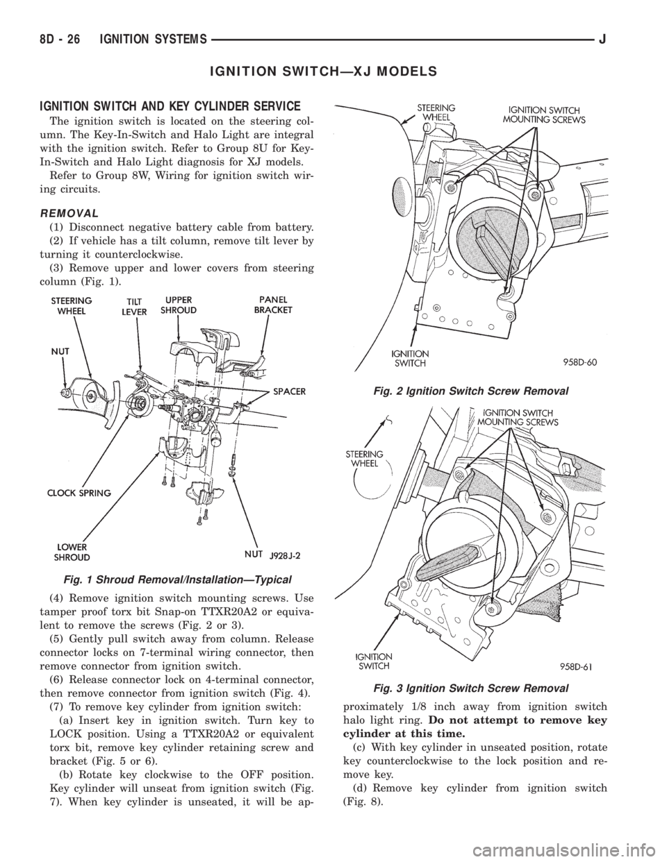
IGNITION SWITCHÐXJ MODELS
IGNITION SWITCH AND KEY CYLINDER SERVICE
The ignition switch is located on the steering col-
umn. The Key-In-Switch and Halo Light are integral
with the ignition switch. Refer to Group 8U for Key-
In-Switch and Halo Light diagnosis for XJ models.
Refer to Group 8W, Wiring for ignition switch wir-
ing circuits.
REMOVAL
(1) Disconnect negative battery cable from battery.
(2) If vehicle has a tilt column, remove tilt lever by
turning it counterclockwise.
(3) Remove upper and lower covers from steering
column (Fig. 1).
(4) Remove ignition switch mounting screws. Use
tamper proof torx bit Snap-on TTXR20A2 or equiva-
lent to remove the screws (Fig. 2 or 3).
(5) Gently pull switch away from column. Release
connector locks on 7-terminal wiring connector, then
remove connector from ignition switch.
(6) Release connector lock on 4-terminal connector,
then remove connector from ignition switch (Fig. 4).
(7) To remove key cylinder from ignition switch:
(a) Insert key in ignition switch. Turn key to
LOCK position. Using a TTXR20A2 or equivalent
torx bit, remove key cylinder retaining screw and
bracket (Fig. 5 or 6).
(b) Rotate key clockwise to the OFF position.
Key cylinder will unseat from ignition switch (Fig.
7). When key cylinder is unseated, it will be ap-proximately 1/8 inch away from ignition switch
halo light ring.Do not attempt to remove key
cylinder at this time.
(c) With key cylinder in unseated position, rotate
key counterclockwise to the lock position and re-
move key.
(d) Remove key cylinder from ignition switch
(Fig. 8).
Fig. 1 Shroud Removal/InstallationÐTypical
Fig. 2 Ignition Switch Screw Removal
Fig. 3 Ignition Switch Screw Removal
8D - 26 IGNITION SYSTEMSJ
Page 408 of 2158
(2) Carefully remove grille from speaker by placing
fingertips on outer circumference of grille and gently
prying straight down to disengage 4 mounting tabs.
(3) Drill out rivets securing speaker to sound bar.
(4) Lower speaker far enough to unplug wiring
from connector.
(5) Reverse removal procedures to install. Use new
rivets to secure speaker. Be certain that tabs on
speaker grille are inserted through slots in sound
bar.
SOUND BAR REMOVE/INSTALL - XJ
(1) Disconnect battery negative cable.
(2) Remove lens from cargo lamp housing.
(3) Remove screws securing left and right rear side
roof rail garnish moldings.
(4) Remove left and right rear side roof rail gar-
nish moldings.
(5) Remove 2 push-on retainers from pins inside
cargo lamp housing securing sound bar to rear roof
bow.
(6) Lower sound bar from roof area and remove
from vehicle.
(7) Reverse removal procedures to install. Use 2
new push-on retainers.
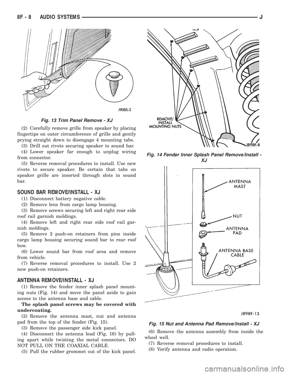
ANTENNA REMOVE/INSTALL - XJ
(1) Remove the fender inner splash panel mount-
ing nuts (Fig. 14) and move the panel aside to gain
access to the antenna base and cable.
The splash panel screws may be covered with
undercoating.
(2) Remove the antenna mast, nut and antenna
pad from the top of the fender (Fig. 15).
(3) Remove the passenger side kick panel.
(4) Disconnect the antenna lead (Fig. 16) by pull-
ing apart while twisting the metal connectors. DO
NOT PULL ON THE COAXIAL CABLE.
(5) Pull the rubber grommet out of the kick panel.(6) Remove the antenna assembly from inside the
wheel well.
(7) Reverse removal procedures to install.
(8) Verify antenna and radio operation.
Fig. 13 Trim Panel Remove - XJ
Fig. 14 Fender Inner Splash Panel Remove/Install -
XJ
Fig. 15 Nut and Antenna Pad Remove/Install - XJ
8F - 8 AUDIO SYSTEMSJ
Page 431 of 2158
SERVICE PROCEDURES
WARNING: ON VEHICLES EQUIPPED WITH AN AIRBAG,
REFER TO GROUP 8M - RESTRAINT SYSTEMS BEFORE
ATTEMPTING STEERING WHEEL COMPONENT DIAGNO-
SIS OR SERVICE. FAILURE TO TAKE PROPER PRECAU-
TIONS COULD RESULT IN ACCIDENTAL AIRBAG DE-
PLOYMENT AND POSSIBLE PERSONAL INJURY.
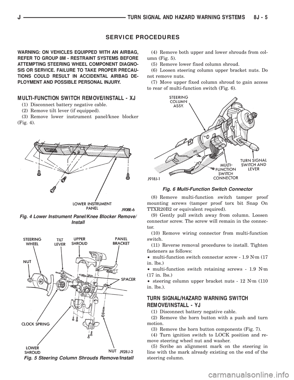
MULTI-FUNCTION SWITCH REMOVE/INSTALL - XJ
(1) Disconnect battery negative cable.
(2) Remove tilt lever (if equipped).
(3) Remove lower instrument panel/knee blocker
(Fig. 4).(4) Remove both upper and lower shrouds from col-
umn (Fig. 5).
(5) Remove lower fixed column shroud.
(6) Loosen steering column upper bracket nuts. Do
not remove nuts.
(7) Move upper fixed column shroud to gain access
to rear of multi-function switch (Fig. 6).
(8) Remove multi-function switch tamper proof
mounting screws (tamper proof torx bit Snap On
TTXR20B2 or equivalent required).
(9) Gently pull switch away from column. Loosen
connector screw. The screw will remain in the connec-
tor.
(10) Remove wiring connector from multi-function
switch.
(11) Reverse removal procedures to install. Tighten
fasteners as follows:
²multi-function switch connector screw - 1.9 Nzm (17
in. lbs.)
²multi-function switch retaining screws - 1.9 Nzm
(17 in. lbs.)
²steering column upper bracket nuts - 12 Nzm(110
in. lbs.).
TURN SIGNAL/HAZARD WARNING SWITCH
REMOVE/INSTALL - YJ
(1) Disconnect battery negative cable.
(2) Remove the horn button with a push and turn
motion.
(3) Remove the horn button components (Fig. 7).
(4) Turn ignition switch to LOCK position and re-
move steering wheel nut and washer.
(5) Scribe an alignment mark on the steering in
line with the mark already existing on the end of the
steering column.
Fig. 5 Steering Column Shrouds Remove/Install
Fig. 4 Lower Instrument Panel/Knee Blocker Remove/
Install
Fig. 6 Multi-Function Switch Connector
JTURN SIGNAL AND HAZARD WARNING SYSTEMS 8J - 5
Page 441 of 2158
(8) Remove the wiper motor mounting screws.
(9) Remove the wiper motor.
(10) Reverse removal procedures to install. Tighten
pivot pin retaining nut to 4 Nzm (32 in. lbs.). Lubri-
cate the bezel nipples with a small amount of water
when installing washer hoses. The liftgate wiper
blade should be installed parallel to window opening
and no closer than 5mm to window seal when oper-
ated on a wet window (Fig. 9).
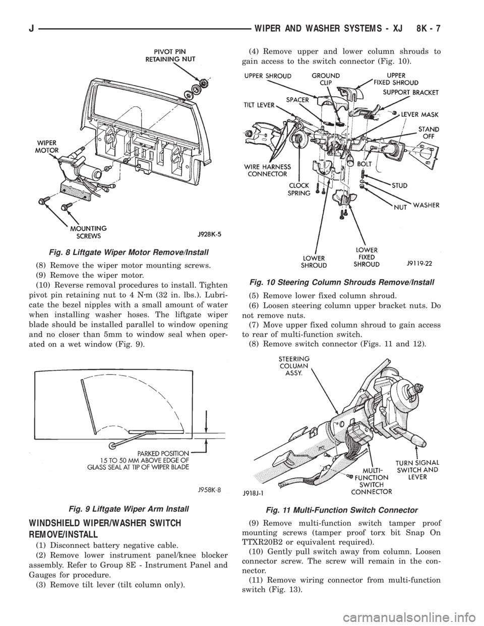
WINDSHIELD WIPER/WASHER SWITCH
REMOVE/INSTALL
(1) Disconnect battery negative cable.
(2) Remove lower instrument panel/knee blocker
assembly. Refer to Group 8E - Instrument Panel and
Gauges for procedure.
(3) Remove tilt lever (tilt column only).(4) Remove upper and lower column shrouds to
gain access to the switch connector (Fig. 10).
(5) Remove lower fixed column shroud.
(6) Loosen steering column upper bracket nuts. Do
not remove nuts.
(7) Move upper fixed column shroud to gain access
to rear of multi-function switch.
(8) Remove switch connector (Figs. 11 and 12).
(9) Remove multi-function switch tamper proof
mounting screws (tamper proof torx bit Snap On
TTXR20B2 or equivalent required).
(10) Gently pull switch away from column. Loosen
connector screw. The screw will remain in the con-
nector.
(11) Remove wiring connector from multi-function
switch (Fig. 13).
Fig. 8 Liftgate Wiper Motor Remove/Install
Fig. 9 Liftgate Wiper Arm Install
Fig. 10 Steering Column Shrouds Remove/Install
Fig. 11 Multi-Function Switch Connector
JWIPER AND WASHER SYSTEMS - XJ 8K - 7
Page 471 of 2158
INSTALLATION
(1) Squeeze the tabs on the side of the fog lamp
switch and insert the switch in the instrument panel
cavity.
(2) Connect the wire harness connector to the
switch.
(3) Install the fog lamp switch cover.
(4) Position the bezel on the instrument panel and
install the attaching screws. Tighten the screws se-
curely.
MULTI-FUNCTION SWITCH SERVICE
PROCEDURESÐXJ
REMOVAL
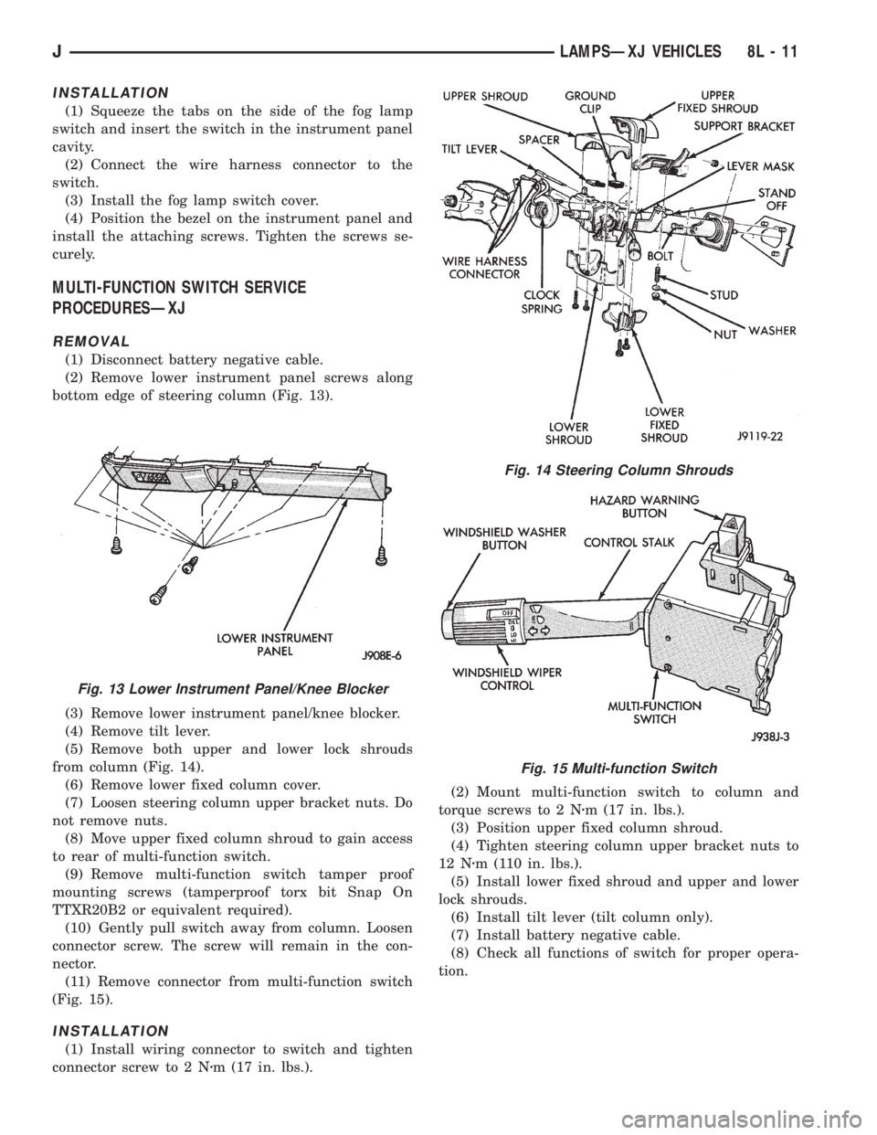
(1) Disconnect battery negative cable.
(2) Remove lower instrument panel screws along
bottom edge of steering column (Fig. 13).
(3) Remove lower instrument panel/knee blocker.
(4) Remove tilt lever.
(5) Remove both upper and lower lock shrouds
from column (Fig. 14).
(6) Remove lower fixed column cover.
(7) Loosen steering column upper bracket nuts. Do
not remove nuts.
(8) Move upper fixed column shroud to gain access
to rear of multi-function switch.
(9) Remove multi-function switch tamper proof
mounting screws (tamperproof torx bit Snap On
TTXR20B2 or equivalent required).
(10) Gently pull switch away from column. Loosen
connector screw. The screw will remain in the con-
nector.
(11) Remove connector from multi-function switch
(Fig. 15).
INSTALLATION
(1) Install wiring connector to switch and tighten
connector screw to 2 Nzm (17 in. lbs.).(2) Mount multi-function switch to column and
torque screws to 2 Nzm (17 in. lbs.).
(3) Position upper fixed column shroud.
(4) Tighten steering column upper bracket nuts to
12 Nzm (110 in. lbs.).
(5) Install lower fixed shroud and upper and lower
lock shrouds.
(6) Install tilt lever (tilt column only).
(7) Install battery negative cable.
(8) Check all functions of switch for proper opera-
tion.
Fig. 13 Lower Instrument Panel/Knee Blocker
Fig. 14 Steering Column Shrouds
Fig. 15 Multi-function Switch
JLAMPSÐXJ VEHICLES 8L - 11