1995 JEEP YJ tailgate
[x] Cancel search: tailgatePage 51 of 2158

(2) Note any indication of drum/rotor overheating,
wheel dragging or the vehicle pulling to one side
when the brakes are applied.
(3) Evaluate any performance complaints received
from the owner/operator.
(4) Repair the brake system as necessary. Refer to
Group, 5 Brakes for additional information and ser-
vice procedures.
TIRES
RECOMMENDED MAINTENANCE
The general condition of the tires and the inflation
pressures should be inspected at the same time the
engine oil is changed and the oil filter is replaced.
In addition, the tires/wheels should be rotated at
the intervals described in the Maintenance Schedules
section of this group.
INSPECTION
Inspect the tires for excessive wear, damage, etc.
Test the tires for the recommended inflation pres-sure. Refer to the tire inflation pressure decal located
on the inside of the glove box door, and also to Group
22, Tires And Wheels.
ROTATION
Refer to Group 22, Tires And Wheels for the recom-
mended method of tire/wheel rotation for a Jeep ve-
hicle.
BODY COMPONENTS
LUBRICATION REQUIREMENTS
All Jeep operating mechanisms and linkages
should be lubricated when necessary. The door
weatherstrip seals should be lubricated to prolong
their life as well as to improve door sealing.
LUBRICANT SPECIFICATIONS
All applicable exterior and interior vehicle operat-
ing mechanisms should be:
²Inspected
²Cleaned
²Pivot/sliding contact areas on the mechanisms
should then be lubricated.
Multi-purpose NLGI GC-LB MOPAR Multi-Mileage
Lubricant or an equivalent, should be used to lubri-
cate the mechanisms. The door weatherstrip seals
should be lubricated with silicone lubricant spray.
Refer to the Body Lubricant Specifications chart be-
low for additional lubricant applications.
LUBRICATION
All pivoting and sliding contact areas, should be lu-
bricated periodically to ensure quiet, easy operation
and to protect against wear and corrosion. Areas in-
clude:
²Seat tracks.
²Door hinges/latches/strikers.
²Liftgate/tailgate/hood hinges (Fig. 11).
(1) As required, lubricate the body components
with the specified lubricants.
(2) Apply silicone lubricant to a cloth and wipe it
on door seals to avoid over-spray that can soil pas-
senger clothing.
(3) Before applying lubricant, the component
should be wiped clean. After lubrication, any excess
lubricant should be removed.
(4) The door lock cylinders should be lubricated 2
times each year (preferably autumn and spring):
²Spray a small amount of lock cylinder lubricant di-
rectly into the lock cylinder.
²Apply a small amount to the key and insert it into
the lock cylinder.
²Rotate it to the locked position and then back to
the unlocked position several times.
²Remove the key. Wipe the lubricant from it with a
clean cloth to avoid soiling of clothing.
Fig. 9 Park Brake Equalizer (XJ)ÐTypical
Fig. 10 Park Brake Equalizer (YJ)ÐTypical
0 - 32 LUBRICATION AND MAINTENANCEJ
Page 1401 of 2158
BUMPERS
INDEX
page page
Frame Crossmember Cover................. 16
Front Bumper............................ 16Rear Bumper............................ 16
Service Information........................ 16
SERVICE INFORMATION
In some cases, components in the following proce-
dures either support, or are hidden by other compo-
nents.
FRONT BUMPER
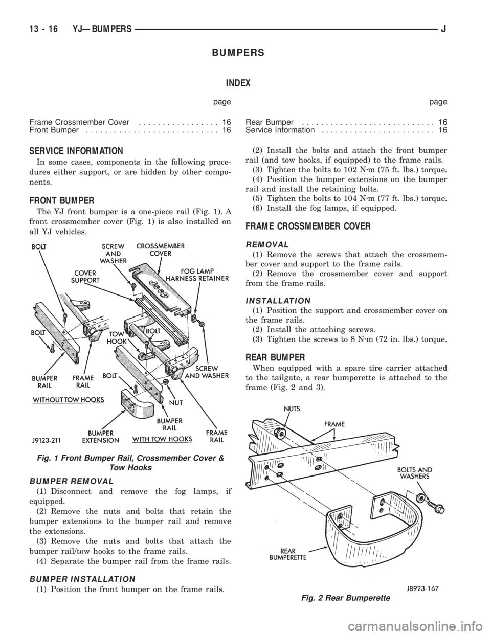
The YJ front bumper is a one-piece rail (Fig. 1). A
front crossmember cover (Fig. 1) is also installed on
all YJ vehicles.
BUMPER REMOVAL
(1) Disconnect and remove the fog lamps, if
equipped.
(2) Remove the nuts and bolts that retain the
bumper extensions to the bumper rail and remove
the extensions.
(3) Remove the nuts and bolts that attach the
bumper rail/tow hooks to the frame rails.
(4) Separate the bumper rail from the frame rails.
BUMPER INSTALLATION
(1) Position the front bumper on the frame rails.(2) Install the bolts and attach the front bumper
rail (and tow hooks, if equipped) to the frame rails.
(3) Tighten the bolts to 102 Nzm (75 ft. lbs.) torque.
(4) Position the bumper extensions on the bumper
rail and install the retaining bolts.
(5) Tighten the bolts to 104 Nzm (77 ft. lbs.) torque.
(6) Install the fog lamps, if equipped.
FRAME CROSSMEMBER COVER
REMOVAL
(1) Remove the screws that attach the crossmem-
ber cover and support to the frame rails.
(2) Remove the crossmember cover and support
from the frame rails.
INSTALLATION
(1) Position the support and crossmember cover on
the frame rails.
(2) Install the attaching screws.
(3) Tighten the screws to 8 Nzm (72 in. lbs.) torque.
REAR BUMPER
When equipped with a spare tire carrier attached
to the tailgate, a rear bumperette is attached to the
frame (Fig. 2 and 3).
Fig. 2 Rear Bumperette
Fig. 1 Front Bumper Rail, Crossmember Cover &
Tow Hooks
13 - 16 YJÐBUMPERSJ
Page 1942 of 2158
COMPLETE REPLACEMENT
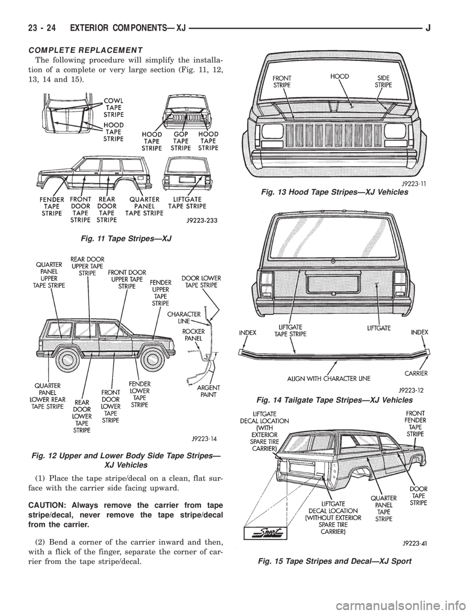
The following procedure will simplify the installa-
tion of a complete or very large section (Fig. 11, 12,
13, 14 and 15).
(1) Place the tape stripe/decal on a clean, flat sur-
face with the carrier side facing upward.
CAUTION: Always remove the carrier from tape
stripe/decal, never remove the tape stripe/decal
from the carrier.
(2) Bend a corner of the carrier inward and then,
with a flick of the finger, separate the corner of car-
rier from the tape stripe/decal.
Fig. 11 Tape StripesÐXJ
Fig. 12 Upper and Lower Body Side Tape StripesÐ
XJ Vehicles
Fig. 13 Hood Tape StripesÐXJ Vehicles
Fig. 14 Tailgate Tape StripesÐXJ Vehicles
Fig. 15 Tape Stripes and DecalÐXJ Sport
23 - 24 EXTERIOR COMPONENTSÐXJJ
Page 2022 of 2158
EXTERIOR COMPONENTS
INDEX
page page
Battery TrayÐYJ......................... 110
Body Side Step MoldingÐYJ................ 115
Body Stripes/DecalsÐYJ................... 116
Cowl Grille and ScreenÐYJ................ 109
Cowl Weatherstrip SealÐYJ................ 109
Exterior Nameplates (Adhesive-Backed)ÐYJ.... 120
External Spare/Wheel Tire CarrierÐYJ........ 133
Fender FlareÐYJ........................ 114
Fender Inner Splash ShieldsÐYJ............. 116
Fender Splash ApronsÐYJ................. 115
FendersÐYJ............................ 110
Fuel Filler Protector/NozzleÐYJ............. 121
Half Metal Door Mirror (External)ÐYJ......... 121
Hard Top Liftgate GlassÐYJ................ 124
Hard Top RepairÐYJ..................... 127
Hard Top Roof VentÐYJ................... 127
Hard TopÐYJ........................... 126Hood AlignmentÐYJ...................... 107
Hood Insulator PanelÐYJ.................. 107
Hood Safety LatchÐYJ.................... 109
HoodÐYJ.............................. 107
Liftgate Glass Weatherstrip Seal ReplacementÐYJ. 125
Radiator Grille AppliqueÐYJ................ 104
Soft Top Service InformationÐYJ............. 127
Soft Top ServiceÐYJ..................... 129
Sport BarÐYJ........................... 132
Tailgate AdjustmentÐYJ................... 121
Tailgate HingeÐYJ....................... 121
Tailgate Latch and Release HandleÐYJ........ 122
Tailgate Latch StrikerÐYJ.................. 123
Tailgate Lock CylinderÐYJ................. 122
Tailgate Weatherstrip SealÐYJ.............. 123
TailgateÐYJ............................ 121
Wheelhouse Splash LinersÐYJ.............. 115
RADIATOR GRILLE APPLIQUEÐYJ
REMOVAL
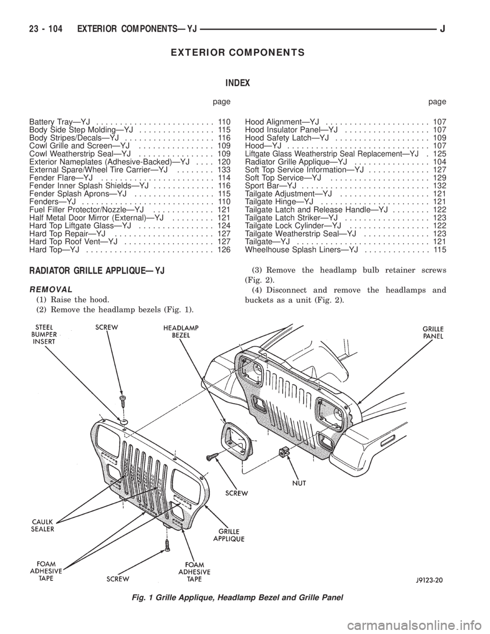
(1) Raise the hood.
(2) Remove the headlamp bezels (Fig. 1).(3) Remove the headlamp bulb retainer screws
(Fig. 2).
(4) Disconnect and remove the headlamps and
buckets as a unit (Fig. 2).
Fig. 1 Grille Applique, Headlamp Bezel and Grille Panel
23 - 104 EXTERIOR COMPONENTSÐYJJ
Page 2039 of 2158
(3) Position the replacement nameplate on the
panel and apply inward force to seat it.
FUEL FILLER PROTECTOR/NOZZLEÐYJ
REMOVAL
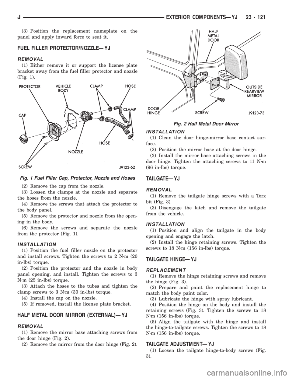
(1) Either remove it or support the license plate
bracket away from the fuel filler protector and nozzle
(Fig. 1).
(2) Remove the cap from the nozzle.
(3) Loosen the clamps at the nozzle and separate
the hoses from the nozzle.
(4) Remove the screws that attach the protector to
the body panel.
(5) Remove the protector and nozzle from the open-
ing in the body.
(6) Remove the screws and separate the nozzle
from the protector (Fig. 1).
INSTALLATION
(1) Position the fuel filler nozzle on the protector
and install screws. Tighten the screws to 2 Nzm (20
in-lbs) torque.
(2) Position the protector and the nozzle in body
panel opening, and install. Tighten the screws to 3
Nzm (25 in-lbs) torque.
(3) Attach the hoses to the tubes and tighten the
clamp screws to 3 Nzm (30 in-lbs) torque.
(4) Install the cap on the nozzle.
(5) If removed, install the license plate bracket.
HALF METAL DOOR MIRROR (EXTERNAL)ÐYJ
REMOVAL
(1) Remove the mirror base attaching screws from
the door hinge (Fig. 2).
(2) Remove the mirror from the door hinge (Fig. 2).
INSTALLATION
(1) Clean the door hinge-mirror base contact sur-
face.
(2) Position the mirror base at the door hinge.
(3) Install the mirror base attaching screws in the
door hinge. Tighten the attaching screws to 11 Nzm
(96 in-lbs) torque.
TAILGATEÐYJ
REMOVAL
(1) Remove the tailgate hinge screws with a Torx
bit (Fig. 3).
(3) Disengage the latch and remove the tailgate
from the vehicle.
INSTALLATION
(1) Position and align the tailgate in the body
opening and engage the latch.
(2) Install the hinge retaining screws. Tighten the
screws to 18 Nzm (156 in-lbs) torque.
TAILGATE HINGEÐYJ
REPLACEMENT
(1) Remove the hinge retaining screws and remove
the hinge (Fig. 3).
(2) Prepare and paint the replacement hinge to
match the body paint color.
(3) Lubricate the hinge with spray lubricant.
(4) Position the hinge on the body and install the
retaining screws (Fig. 3). Tighten the screws to 18
Nzm (156 in-lbs) torque.
(5) Align the tailgate with the hinge and install
the hinge-to-tailgate screws. Tighten the screws to 18
Nzm (156 in-lbs) torque.
TAILGATE ADJUSTMENTÐYJ
(1) Loosen the tailgate hinge-to-body screws (Fig.
3).
Fig. 1 Fuel Filler Cap, Protector, Nozzle and Hoses
Fig. 2 Half Metal Door Mirror
JEXTERIOR COMPONENTSÐYJ 23 - 121
Page 2040 of 2158
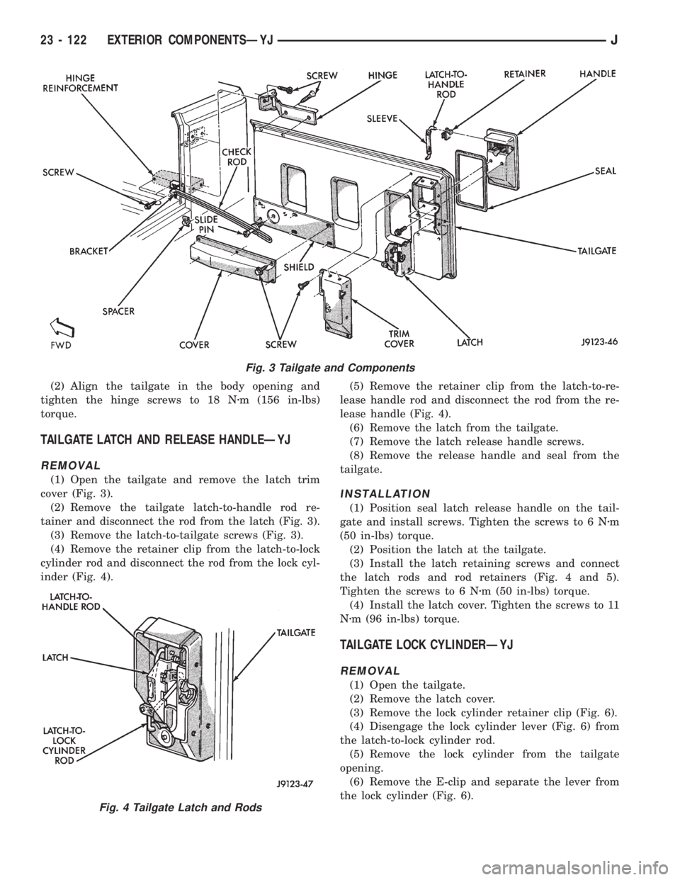
(2) Align the tailgate in the body opening and
tighten the hinge screws to 18 Nzm (156 in-lbs)
torque.
TAILGATE LATCH AND RELEASE HANDLEÐYJ
REMOVAL
(1) Open the tailgate and remove the latch trim
cover (Fig. 3).
(2) Remove the tailgate latch-to-handle rod re-
tainer and disconnect the rod from the latch (Fig. 3).
(3) Remove the latch-to-tailgate screws (Fig. 3).
(4) Remove the retainer clip from the latch-to-lock
cylinder rod and disconnect the rod from the lock cyl-
inder (Fig. 4).(5) Remove the retainer clip from the latch-to-re-
lease handle rod and disconnect the rod from the re-
lease handle (Fig. 4).
(6) Remove the latch from the tailgate.
(7) Remove the latch release handle screws.
(8) Remove the release handle and seal from the
tailgate.
INSTALLATION
(1) Position seal latch release handle on the tail-
gate and install screws. Tighten the screws to 6 Nzm
(50 in-lbs) torque.
(2) Position the latch at the tailgate.
(3) Install the latch retaining screws and connect
the latch rods and rod retainers (Fig. 4 and 5).
Tighten the screws to 6 Nzm (50 in-lbs) torque.
(4) Install the latch cover. Tighten the screws to 11
Nzm (96 in-lbs) torque.
TAILGATE LOCK CYLINDERÐYJ
REMOVAL
(1) Open the tailgate.
(2) Remove the latch cover.
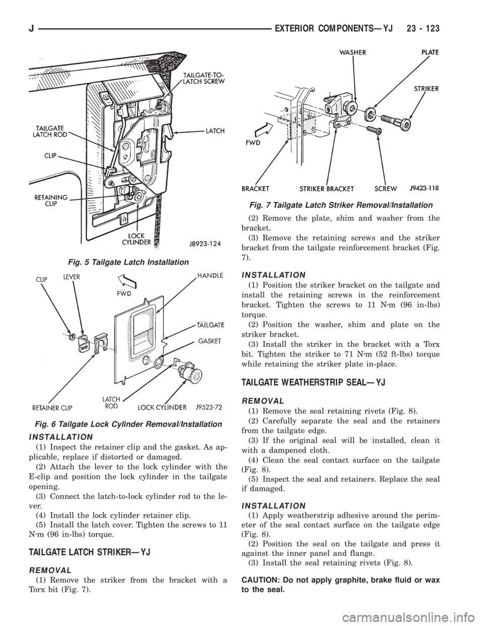
(3) Remove the lock cylinder retainer clip (Fig. 6).
(4) Disengage the lock cylinder lever (Fig. 6) from
the latch-to-lock cylinder rod.
(5) Remove the lock cylinder from the tailgate
opening.
(6) Remove the E-clip and separate the lever from
the lock cylinder (Fig. 6).
Fig. 3 Tailgate and Components
Fig. 4 Tailgate Latch and Rods
23 - 122 EXTERIOR COMPONENTSÐYJJ
Page 2041 of 2158
INSTALLATION
(1) Inspect the retainer clip and the gasket. As ap-
plicable, replace if distorted or damaged.
(2) Attach the lever to the lock cylinder with the
E-clip and position the lock cylinder in the tailgate
opening.
(3) Connect the latch-to-lock cylinder rod to the le-
ver.
(4) Install the lock cylinder retainer clip.
(5) Install the latch cover. Tighten the screws to 11
Nzm (96 in-lbs) torque.
TAILGATE LATCH STRIKERÐYJ
REMOVAL
(1) Remove the striker from the bracket with a
Torx bit (Fig. 7).(2) Remove the plate, shim and washer from the
bracket.
(3) Remove the retaining screws and the striker
bracket from the tailgate reinforcement bracket (Fig.
7).
INSTALLATION
(1) Position the striker bracket on the tailgate and
install the retaining screws in the reinforcement
bracket. Tighten the screws to 11 Nzm (96 in-lbs)
torque.
(2) Position the washer, shim and plate on the
striker bracket.
(3) Install the striker in the bracket with a Torx
bit. Tighten the striker to 71 Nzm (52 ft-lbs) torque
while retaining the striker plate in-place.
TAILGATE WEATHERSTRIP SEALÐYJ
REMOVAL
(1) Remove the seal retaining rivets (Fig. 8).
(2) Carefully separate the seal and the retainers
from the tailgate edge.
(3) If the original seal will be installed, clean it
with a dampened cloth.
(4) Clean the seal contact surface on the tailgate
(Fig. 8).
(5) Inspect the seal and retainers. Replace the seal
if damaged.
INSTALLATION
(1) Apply weatherstrip adhesive around the perim-
eter of the seal contact surface on the tailgate edge
(Fig. 8).
(2) Position the seal on the tailgate and press it
against the inner panel and flange.
(3) Install the seal retaining rivets (Fig. 8).
CAUTION: Do not apply graphite, brake fluid or wax
to the seal.
Fig. 5 Tailgate Latch Installation
Fig. 6 Tailgate Lock Cylinder Removal/Installation
Fig. 7 Tailgate Latch Striker Removal/Installation
JEXTERIOR COMPONENTSÐYJ 23 - 123
Page 2042 of 2158
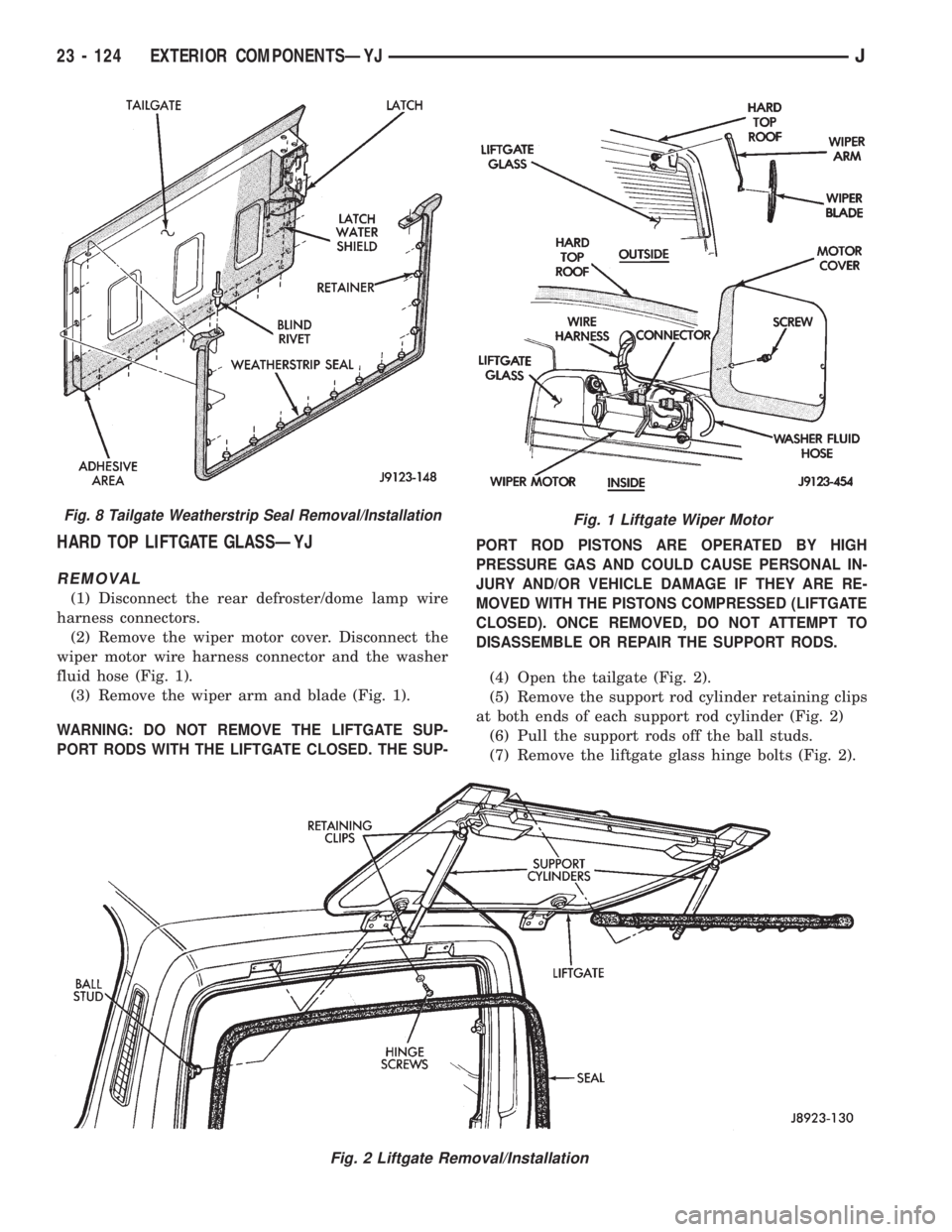
HARD TOP LIFTGATE GLASSÐYJ
REMOVAL
(1) Disconnect the rear defroster/dome lamp wire
harness connectors.
(2) Remove the wiper motor cover. Disconnect the
wiper motor wire harness connector and the washer
fluid hose (Fig. 1).
(3) Remove the wiper arm and blade (Fig. 1).
WARNING: DO NOT REMOVE THE LIFTGATE SUP-
PORT RODS WITH THE LIFTGATE CLOSED. THE SUP-PORT ROD PISTONS ARE OPERATED BY HIGH
PRESSURE GAS AND COULD CAUSE PERSONAL IN-
JURY AND/OR VEHICLE DAMAGE IF THEY ARE RE-
MOVED WITH THE PISTONS COMPRESSED (LIFTGATE
CLOSED). ONCE REMOVED, DO NOT ATTEMPT TO
DISASSEMBLE OR REPAIR THE SUPPORT RODS.
(4) Open the tailgate (Fig. 2).
(5) Remove the support rod cylinder retaining clips
at both ends of each support rod cylinder (Fig. 2)
(6) Pull the support rods off the ball studs.
(7) Remove the liftgate glass hinge bolts (Fig. 2).
Fig. 1 Liftgate Wiper Motor
Fig. 2 Liftgate Removal/Installation
Fig. 8 Tailgate Weatherstrip Seal Removal/Installation
23 - 124 EXTERIOR COMPONENTSÐYJJ