1995 JEEP YJ roof
[x] Cancel search: roofPage 1978 of 2158

(3) Align the trim panel retainers with the holes in
the liftgate inner panel and force the trim panel in-
ward.
(4) Install the screws to attach the panel upper
sides to the liftgate.
LIFTGATE HINGEÐXJ
REMOVAL
It is not necessary to remove the liftgate to replace
one or both hinges.
(1) Remove the liftgate (headliner) upper trim
molding (Fig. 7).
(2) Remove the hinge-to-roof panel nuts (Fig. 8).
(3) Remove the hinge-to-liftgate screws and remove
the hinge from the liftgate (Fig. 9).
INSTALLATION
(1) Position the gaskets, shim and hinge on the
liftgate and the roof panel (Fig. 10).
(2) Install and tighten hinge-to-roof panel nuts to 9
Nzm (7 ft-lbs) torque.(3) Install the liftgate-to-hinge screws. Tighten
screws to 9 Nzm (7 ft-lbs) torque.
(4) Install the liftgate (headliner) upper trim mold-
ing (Fig. 7).
Fig. 7 Liftgate Upper Trim Molding
Fig. 8 Liftgate Hinge-To-Roof Panel Nuts
Fig. 9 Liftgate Hinges
Fig. 10 Liftgate Hinge, Gaskets and Shim
23 - 60 DOORSÐXJJ
Page 1981 of 2158
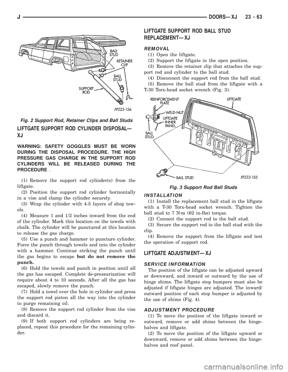
LIFTGATE SUPPORT ROD CYLINDER DISPOSALÐ
XJ
WARNING: SAFETY GOGGLES MUST BE WORN
DURING THE DISPOSAL PROCEDURE. THE HIGH
PRESSURE GAS CHARGE IN THE SUPPORT ROD
CYLINDERS WILL BE RELEASED DURING THE
PROCEDURE.
(1) Remove the support rod cylinder(s) from the
liftgate.
(2) Position the support rod cylinder horizontally
in a vise and clamp the cylinder securely.
(3) Wrap the cylinder with 4-5 layers of shop tow-
els.
(4) Measure 1 and 1/2 inches inward from the end
of the cylinder. Mark this location on the towels with
chalk. The cylinder will be punctured at this location
to release the gas charge.
(5) Use a punch and hammer to puncture cylinder.
Force the punch through towels and into the cylinder
with a hammer. Continue striking the punch until
the gas begins to escapebut do not remove the
punch.
(6) Hold the towels and punch in position until all
the gas has escaped. Complete de-pressurization will
require about 4 to 10 seconds. After all the gas has
escaped, slowly remove the punch.
(7) Hold a towel over the hole in cylinder and press
the support rod piston all the way into the cylinder
to purge remaining oil.
(8) Remove the support rod cylinder from the vise
and discard it.
(9) If both support rod cylinders are being re-
placed, repeat this procedure for the remaining cylin-
der.
LIFTGATE SUPPORT ROD BALL STUD
REPLACEMENTÐXJ
REMOVAL
(1) Open the liftgate.
(2) Support the liftgate in the open position.
(3) Remove the retainer clip that attaches the sup-
port rod and cylinder to the ball stud.
(4) Disconnect the support rod from the ball stud.
(5) Remove the ball stud from the liftgate with a
T-30 Torx-head socket wrench (Fig. 3).
INSTALLATION
(1) Install the replacement ball stud in the liftgate
with a T-30 Torx-head socket wrench. Tighten the
ball stud to 7 Nzm (62 in-lbs) torque.
(2) Connect the support rod to the ball stud.
(3) Secure the support rod to the ball stud with the
clip.
(4) Remove the support from the liftgate and test
the operation of support rod.
LIFTGATE ADJUSTMENTÐXJ
SERVICE INFORMATION
The position of the liftgate can be adjusted upward
or downward, and inward or outward by the use of
hinge shims. The liftgate stop bumpers must also be
adjusted if liftgate hinges are adjusted. The inward/
outward position of each stop bumper is adjusted by
the use of shims (Fig. 4).
ADJUSTMENT PROCEDURE
(1) To move the position of the liftgate inward or
outward, remove or add shims between the hinge-
halves and liftgate.
(2) To move the position of the liftgate upward or
downward, remove or add shims between the hinge-
halves and roof panel.
Fig. 2 Support Rod, Retainer Clips and Ball Studs
Fig. 3 Support Rod Ball Studs
JDOORSÐXJ 23 - 63
Page 1982 of 2158
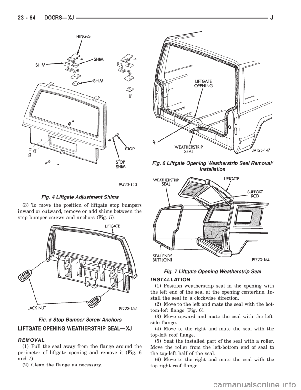
(3) To move the position of liftgate stop bumpers
inward or outward, remove or add shims between the
stop bumper screws and anchors (Fig. 5).
LIFTGATE OPENING WEATHERSTRIP SEALÐXJ
REMOVAL
(1) Pull the seal away from the flange around the
perimeter of liftgate opening and remove it (Fig. 6
and 7).
(2) Clean the flange as necessary.
INSTALLATION
(1) Position weatherstrip seal in the opening with
the left end of the seal at the opening centerline. In-
stall the seal in a clockwise direction.
(2) Move to the left and mate the seal with the bot-
tom-left flange (Fig. 6).
(3) Move upward and mate the seal with the left-
side flange.
(4) Move to the right and mate the seal with the
top-left roof flange.
(5) Seat the installed part of the seal with a roller.
Move the roller from the left-bottom end of seal to
the top-left half of the seal.
(6) Move to the right and mate the seal with the
top-right roof flange.
Fig. 4 Liftgate Adjustment Shims
Fig. 5 Stop Bumper Screw Anchors
Fig. 6 Liftgate Opening Weatherstrip Seal Removal/
Installation
Fig. 7 Liftgate Opening Weatherstrip Seal
23 - 64 DOORSÐXJJ
Page 1985 of 2158
INSTALLATION
(1) Apply adhesive to the act surface on the sup-
port bracket according as follows:
²crush the vial in the plastic housing of the accel-
erator to saturate the felt applicator.
²remove the paper sleeve.
²apply a generous amount of accelerator to the con-
tact surface on the mirror support bracket.
²do not touch the support bracket contact surface
after the accelerator has been applied.
²
allow the accelerator to dry for at least five minutes.
and
(2) Apply accelerator to the support bracket con-
tact surface on the windshield glass. Allow the accel-
erator to dry for one minute.
(3) Install the mirror bracket on the windshield
glass as follows:
²apply one drop of adhesive at the center of support
bracket contact surface on windshield glass.
²immediately apply an even coat of adhesive to the
contact surface on the support bracket.
²align the support bracket with the position refer-
ence lines on the windshield glass, then
²press and hold the support bracket in-place for at
least one minute.
Ensure that the mirror support bracket is
correctly aligned because the adhesive will
cure rapidly.
(4) Allow the adhesive to cure for 8-10 minutes,
then remove any residue adhesive with an alcohol-
dampened cloth.
(5) Allow the adhesive to cure for an additional
8-10 minutes before installing the mirror base on the
support bracket.
DESCRIPTION AND OPERATION
SAFETY PRECAUTIONS
WARNING: DO NOT OPERATE THE VEHICLE
WITHIN 24 HOURS OF WINDSHIELD INSTALLATION.
IT TAKES AT LEAST 24 HOURS FOR THE URE-
THANE ADHESIVE TO CURE. IF IT IS NOT CURED,
THE WINDSHIELD MAY NOT PERFORM PROPERLY
IN AN ACCIDENT.
URETHANE ADHESIVES ARE APPLIED AS A SYS-
TEM. USE GLASS CLEANER, GLASS PREP SOL-
VENT, GLASS PRIMER, AND PINCHWELD (FENCE)
PRIMER PROVIDED BY THE ADHESIVE MANUFAC-
TURER. IF NOT, STRUCTURAL INTEGRITY COULD
BE COMPROMISED.
BE SURE TO REFER TO THE URETHANE MANU-
FACTURER'S DIRECTIONS FOR CURING TIME
SPECIFICATIONS, AND DO NOT USE ADHESIVE AF-
TER ITS EXPIRATION DATE.
VAPORS THAT ARE EMITTED FROM THE URE-
THANE ADHESIVE OR PRIMER COULD CAUSE
PERSONAL INJURY, USE THEM IN A WELL VENTI-
LATED AREA.
SKIN CONTACT WITH URETHANE ADHESIVE
SHOULD BE AVOIDED, OR PERSONAL INJURY MAY
RESULT.
ALWAYS WEAR EYE AND HAND PROTECTION
WHEN WORKING WITH GLASS.
CAUTION: Protect all painted or trimmed surfaces
from coming in contact with urethane or primers.
Be careful not to damage painted surfaces when
removing moldings or cutting urethane around
windshield.
It is difficult to salvage a windshield during the re-
moval operation. The windshield is part of the struc-
tural support for the roof. The urethane bonding
used to secure the windshield to the fence is difficult
to cut or clean from any surface. If the moldings are
set in urethane, it would also be unlikely they could
be salvaged. Before removing the windshield, check
the availability of the windshield and moldings from
the parts supplier.
JSTATIONARY WINDOW GLASSÐXJ 23 - 671995 Jeep Cherokee/Wrangler
Publication No. 81-370-5146
TSB 26-05-95 July, 1995
Page 2010 of 2158
INSPECTION
Inspect the rear shoulder/lap belts and buckles. Re-
place any belt that is either cut, frayed, torn or dam-
aged in any way. Replace the shoulder belt if the
retractor is damaged or inoperative.
INSTALLATION
(1) Position the shoulder belt buckle and the lap
belt/buckle anchor plates on the floor panel.
(2) Install the anchor bolts. Tighten the bolts to 37
Nzm (27 ft-lbs) torque.
(3) Position the shoulder belt at the roof rail and
install the upper anchor bolt. Tighten the bolt to 37
Nzm (27 ft-lbs) torque.
(4) Route the shoulder belt through the quarter
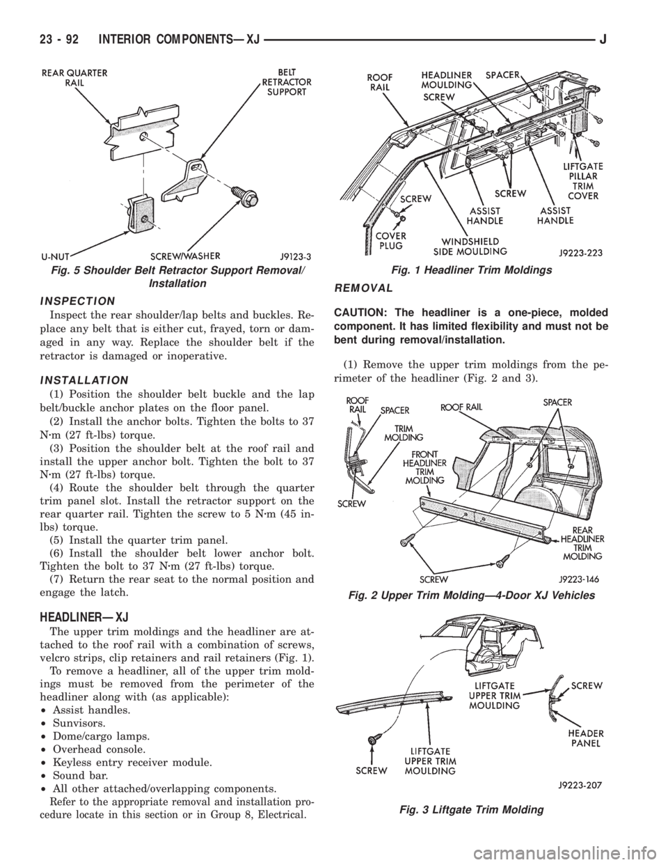
trim panel slot. Install the retractor support on the
rear quarter rail. Tighten the screw to 5 Nzm (45 in-
lbs) torque.
(5) Install the quarter trim panel.
(6) Install the shoulder belt lower anchor bolt.
Tighten the bolt to 37 Nzm (27 ft-lbs) torque.
(7) Return the rear seat to the normal position and
engage the latch.
HEADLINERÐXJ
The upper trim moldings and the headliner are at-
tached to the roof rail with a combination of screws,
velcro strips, clip retainers and rail retainers (Fig. 1).
To remove a headliner, all of the upper trim mold-
ings must be removed from the perimeter of the
headliner along with (as applicable):
²Assist handles.
²Sunvisors.
²Dome/cargo lamps.
²Overhead console.
²Keyless entry receiver module.
²Sound bar.
²All other attached/overlapping components.
Refer to the appropriate removal and installation pro-
cedure locate in this section or in Group 8, Electrical.
REMOVAL
CAUTION: The headliner is a one-piece, molded
component. It has limited flexibility and must not be
bent during removal/installation.
(1) Remove the upper trim moldings from the pe-
rimeter of the headliner (Fig. 2 and 3).
Fig. 5 Shoulder Belt Retractor Support Removal/
InstallationFig. 1 Headliner Trim Moldings
Fig. 2 Upper Trim MoldingÐ4-Door XJ Vehicles
Fig. 3 Liftgate Trim Molding
23 - 92 INTERIOR COMPONENTSÐXJJ
Page 2011 of 2158
(2) Ensure that all the retainer clips, screws and
Velcro strips are disengaged before removing the
headliner.
HEADLINER INSTALLATION
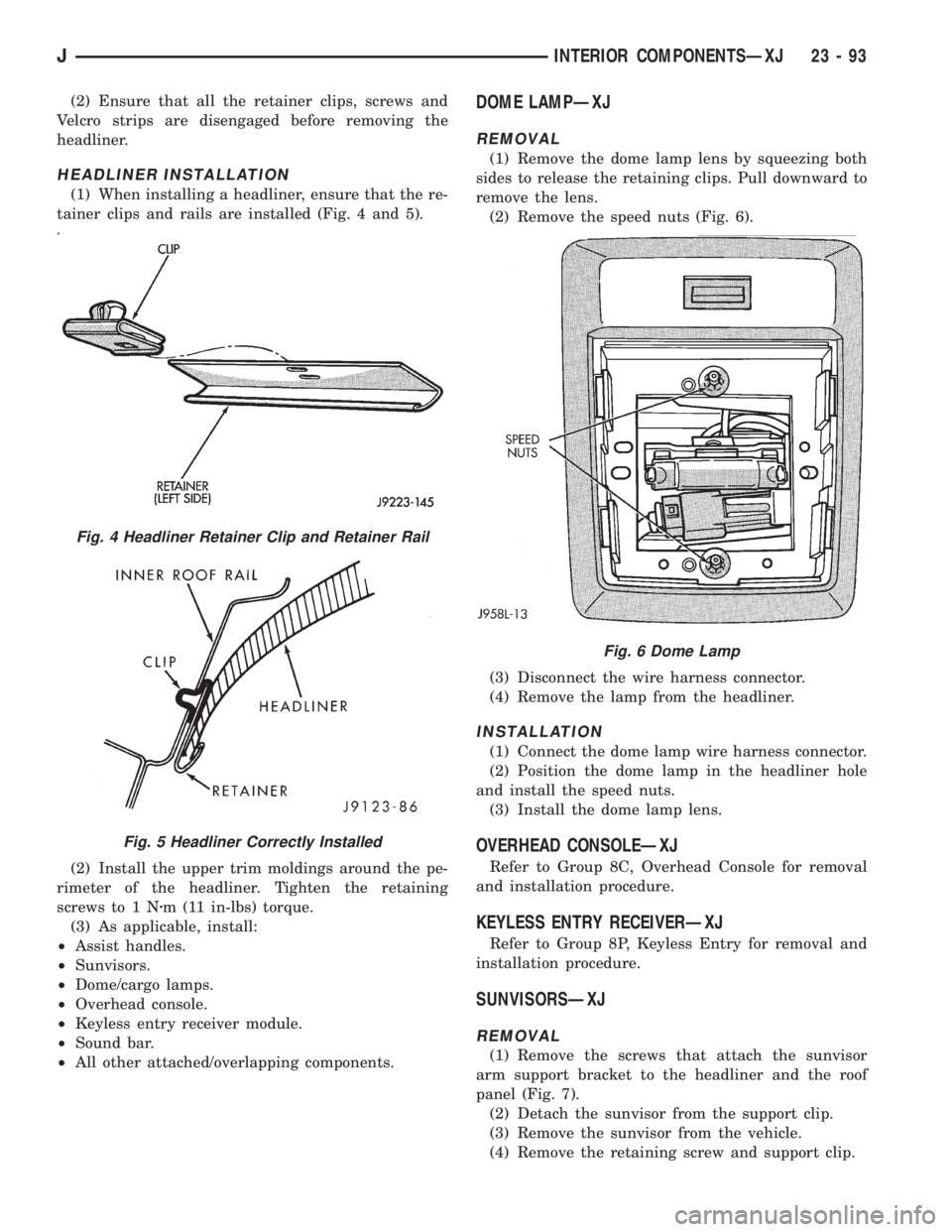
(1) When installing a headliner, ensure that the re-
tainer clips and rails are installed (Fig. 4 and 5).
(2) Install the upper trim moldings around the pe-
rimeter of the headliner. Tighten the retaining
screws to 1 Nzm (11 in-lbs) torque.
(3) As applicable, install:
²Assist handles.
²Sunvisors.
²Dome/cargo lamps.
²Overhead console.
²Keyless entry receiver module.
²Sound bar.
²All other attached/overlapping components.
DOME LAMPÐXJ
REMOVAL
(1) Remove the dome lamp lens by squeezing both
sides to release the retaining clips. Pull downward to
remove the lens.
(2) Remove the speed nuts (Fig. 6).
(3) Disconnect the wire harness connector.
(4) Remove the lamp from the headliner.
INSTALLATION
(1) Connect the dome lamp wire harness connector.
(2) Position the dome lamp in the headliner hole
and install the speed nuts.
(3) Install the dome lamp lens.
OVERHEAD CONSOLEÐXJ
Refer to Group 8C, Overhead Console for removal
and installation procedure.
KEYLESS ENTRY RECEIVERÐXJ
Refer to Group 8P, Keyless Entry for removal and
installation procedure.
SUNVISORSÐXJ
REMOVAL
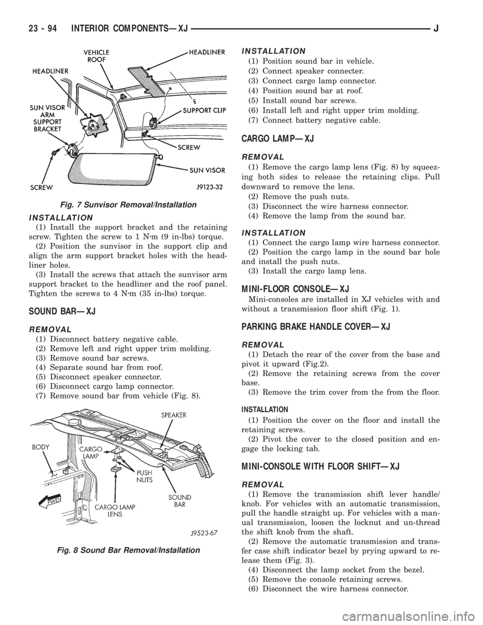
(1) Remove the screws that attach the sunvisor
arm support bracket to the headliner and the roof
panel (Fig. 7).
(2) Detach the sunvisor from the support clip.
(3) Remove the sunvisor from the vehicle.
(4) Remove the retaining screw and support clip.
Fig. 4 Headliner Retainer Clip and Retainer Rail
Fig. 5 Headliner Correctly Installed
Fig. 6 Dome Lamp
JINTERIOR COMPONENTSÐXJ 23 - 93
Page 2012 of 2158
INSTALLATION
(1) Install the support bracket and the retaining
screw. Tighten the screw to 1 Nzm (9 in-lbs) torque.
(2) Position the sunvisor in the support clip and
align the arm support bracket holes with the head-
liner holes.
(3) Install the screws that attach the sunvisor arm
support bracket to the headliner and the roof panel.
Tighten the screws to 4 Nzm (35 in-lbs) torque.
SOUND BARÐXJ
REMOVAL
(1) Disconnect battery negative cable.
(2) Remove left and right upper trim molding.
(3) Remove sound bar screws.
(4) Separate sound bar from roof.
(5) Disconnect speaker connector.
(6) Disconnect cargo lamp connector.
(7) Remove sound bar from vehicle (Fig. 8).
INSTALLATION
(1) Position sound bar in vehicle.
(2) Connect speaker connecter.
(3) Connect cargo lamp connector.
(4) Position sound bar at roof.
(5) Install sound bar screws.
(6) Install left and right upper trim molding.
(7) Connect battery negative cable.
CARGO LAMPÐXJ
REMOVAL
(1) Remove the cargo lamp lens (Fig. 8) by squeez-
ing both sides to release the retaining clips. Pull
downward to remove the lens.
(2) Remove the push nuts.
(3) Disconnect the wire harness connector.
(4) Remove the lamp from the sound bar.
INSTALLATION
(1) Connect the cargo lamp wire harness connector.
(2) Position the cargo lamp in the sound bar hole
and install the push nuts.
(3) Install the cargo lamp lens.
MINI-FLOOR CONSOLEÐXJ
Mini-consoles are installed in XJ vehicles with and
without a transmission floor shift (Fig. 1).
PARKING BRAKE HANDLE COVERÐXJ
REMOVAL
(1) Detach the rear of the cover from the base and
pivot it upward (Fig.2).
(2) Remove the retaining screws from the cover
base.
(3) Remove the trim cover from the from the floor.
INSTALLATION
(1) Position the cover on the floor and install the
retaining screws.
(2) Pivot the cover to the closed position and en-
gage the locking tab.
MINI-CONSOLE WITH FLOOR SHIFTÐXJ
REMOVAL
(1) Remove the transmission shift lever handle/
knob. For vehicles with an automatic transmission,
pull the handle straight up. For vehicles with a man-
ual transmission, loosen the locknut and un-thread
the shift knob from the shaft.
(2) Remove the automatic transmission and trans-
fer case shift indicator bezel by prying upward to re-
lease them (Fig. 3).
(4) Disconnect the lamp socket from the bezel.
(5) Remove the console retaining screws.
(6) Disconnect the wire harness connector.
Fig. 7 Sunvisor Removal/Installation
Fig. 8 Sound Bar Removal/Installation
23 - 94 INTERIOR COMPONENTSÐXJJ
Page 2022 of 2158
EXTERIOR COMPONENTS
INDEX
page page
Battery TrayÐYJ......................... 110
Body Side Step MoldingÐYJ................ 115
Body Stripes/DecalsÐYJ................... 116
Cowl Grille and ScreenÐYJ................ 109
Cowl Weatherstrip SealÐYJ................ 109
Exterior Nameplates (Adhesive-Backed)ÐYJ.... 120
External Spare/Wheel Tire CarrierÐYJ........ 133
Fender FlareÐYJ........................ 114
Fender Inner Splash ShieldsÐYJ............. 116
Fender Splash ApronsÐYJ................. 115
FendersÐYJ............................ 110
Fuel Filler Protector/NozzleÐYJ............. 121
Half Metal Door Mirror (External)ÐYJ......... 121
Hard Top Liftgate GlassÐYJ................ 124
Hard Top RepairÐYJ..................... 127
Hard Top Roof VentÐYJ................... 127
Hard TopÐYJ........................... 126Hood AlignmentÐYJ...................... 107
Hood Insulator PanelÐYJ.................. 107
Hood Safety LatchÐYJ.................... 109
HoodÐYJ.............................. 107
Liftgate Glass Weatherstrip Seal ReplacementÐYJ. 125
Radiator Grille AppliqueÐYJ................ 104
Soft Top Service InformationÐYJ............. 127
Soft Top ServiceÐYJ..................... 129
Sport BarÐYJ........................... 132
Tailgate AdjustmentÐYJ................... 121
Tailgate HingeÐYJ....................... 121
Tailgate Latch and Release HandleÐYJ........ 122
Tailgate Latch StrikerÐYJ.................. 123
Tailgate Lock CylinderÐYJ................. 122
Tailgate Weatherstrip SealÐYJ.............. 123
TailgateÐYJ............................ 121
Wheelhouse Splash LinersÐYJ.............. 115
RADIATOR GRILLE APPLIQUEÐYJ
REMOVAL
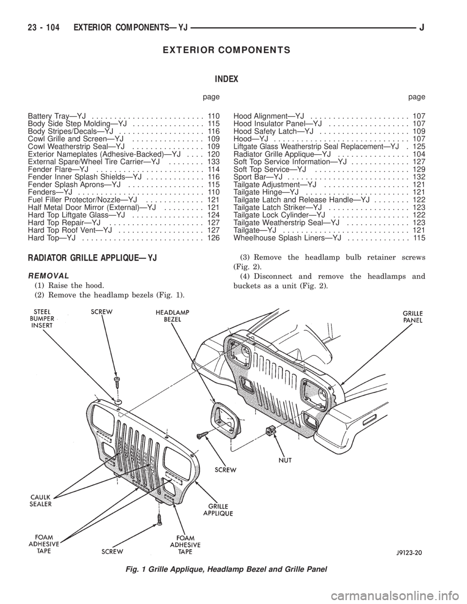
(1) Raise the hood.
(2) Remove the headlamp bezels (Fig. 1).(3) Remove the headlamp bulb retainer screws
(Fig. 2).
(4) Disconnect and remove the headlamps and
buckets as a unit (Fig. 2).
Fig. 1 Grille Applique, Headlamp Bezel and Grille Panel
23 - 104 EXTERIOR COMPONENTSÐYJJ