1995 JEEP YJ compression ratio
[x] Cancel search: compression ratioPage 262 of 2158

WARNING: HOT, PRESSURIZED COOLANT CAN
CAUSE INJURY BY SCALDING.
Carefully remove the radiator pressure cap from
the filler neck and check the coolant level. Push
down on the cap to disengage it from the stop tabs.
Wipe the inner part of the filler neck and examine
the lower inside sealing seat for nicks, cracks, paint,
dirt and solder residue. Inspect the reserve/overflow
tank tube for internal obstructions. Insert a wire
through the tube to be sure it is not obstructed.
Inspect the cams on the outside part of the filler
neck. If the cams are bent, seating of pressure cap
valve and tester seal will be affected. Replace cap if
cams are bent.
Attach pressure tester 7700 (or an equivalent) to
the radiator filler neck (Fig. 21).Operate the tester pump to apply 124 kPa (18 psi)
pressure to the system. If the hoses enlarge exces-
sively or bulge while testing, replace as necessary.
Observe the gauge pointer and determine the condi-
tion of the cooling system according to the following
criteria:
²Holds Steady: If the pointer remains steady for
two minutes, there are no serious coolant leaks in
the system. However, there could be an internal leak
that does not appear with normal system test pres-
sure. Inspect for interior leakage or do the Internal
Leakage Test. Do this if it is certain that coolant is
being lost and no leaks can be detected.
²Drops Slowly: Shows a small leak or seepage is oc-
curring. Examine all connections for seepage or slight
leakage with a flashlight. Inspect the radiator, hoses,
gasket edges and heater. Seal any small leak holes
with a Sealer Lubricant or equivalent. Repair leak
holes and reinspect the system with pressure ap-
plied.
²Drops Quickly: Shows that a serious leakage is oc-
curring. Examine the system for serious external
leakage. If no leaks are visible, inspect for internal
leakage. Large radiator leak holes should be repaired
by a reputable radiator repair shop.
INTERNAL LEAKAGE INSPECTION
Remove the engine oil pan drain plug and drain a
small amount of engine oil. Coolant, being heavier
than engine oil, will drain first. Another way of test-
ing is to operate the engine and check for water glob-
ules on the engine oil dipstick. Also inspect the
automatic transmission oil dipstick for water glob-
ules. Inspect the automatic transmission fluid cooler
for leakage. Operate the engine without the pressure
cap on the radiator until thermostat opens.
Attach a pressure tester to the filler neck. If pres-
sure builds up quickly, a leak exists as a result of a
faulty cylinder head gasket or crack in the engine.
Repair as necessary.
WARNING: DO NOT ALLOW PRESSURE TO EX-
CEED 124 KPA (18 PSI). TURN THE ENGINE OFF.
TO RELEASE THE PRESSURE, ROCK THE TESTER
FROM SIDE TO SIDE. WHEN REMOVING THE
TESTER, DO NOT TURN THE TESTER MORE THAN
1/2 TURN IF THE SYSTEM IS UNDER PRESSURE.
If there is no immediate pressure increase, pump
the pressure tester until the indicated pressure is
within the system range. Vibration of the gauge
pointer indicates compression or combustion leakage
into the cooling system.
WARNING: DO NOT DISCONNECT THE SPARK
PLUG WIRES WHILE THE ENGINE IS OPERATING.
Fig. 20 Leak Detection Using Black LightÐTypical
Fig. 21 Pressurizing SystemÐTypical
JCOOLING SYSTEM SERVICE PROCEDURES 7 - 23
Page 263 of 2158

CAUTION: Do not operate the engine with a spark
plug shorted for more than a minute. The catalytic
converter may be damaged.
Isolate the compression leak by shorting each
spark plug to the cylinder block. The gauge pointer
should stop or decrease vibration when spark plug
for leaking cylinder is shorted. This happens because
of the absence of combustion pressure.
COMBUSTION LEAKAGE TEST (WITHOUT
PRESSURE TESTER)
DO NOT WASTE reusable coolant. If the solution
is clean, drain the coolant into a clean container for
reuse.
WARNING: DO NOT REMOVE THE CYLINDER
BLOCK DRAIN PLUGS OR LOOSEN THE RADIATOR
DRAINCOCK WITH THE SYSTEM HOT AND UNDER
PRESSURE. SERIOUS BURNS FROM COOLANT
CAN OCCUR.
Drain sufficient coolant to allow for thermostat re-
moval. Refer to Thermostat Replacement. Disconnect
the water pump drive belt.
Disconnect the upper radiator hose from the ther-
mostat housing. Remove the housing and thermostat.
Install the thermostat housing.
Add coolant to the radiator to bring the level to
within 6.3 mm (1/4 in) of the top of the thermostat
housing.
CAUTION: Avoid overheating. Do not operate the
engine for an excessive period of time. Open the
draincock immediately after the test to eliminate
boil over of coolant.
Start the engine and accelerate rapidly three times
(to approximately 3000 rpm) while observing the
coolant. If internal engine combustion gases are leak-
ing into the cooling system, bubbles will appear in
the coolant. If bubbles do not appear, there is no in-
ternal combustion gas leakage.
COOLANT RESERVE/OVERFLOW SYSTEM
The system works along with the radiator pressure
cap. This is done by using thermal expansion and
contraction of the coolant to keep the coolant free of
trapped air. It provides:
²A volume for coolant expansion and contraction.
²A convenient and safe method for checking/adjust-
ing coolant level at atmospheric pressure. This is
done without removing the radiator pressure cap.
²Some reserve coolant to the radiator to cover mi-
nor leaks and evaporation or boiling losses.
As the engine cools, a vacuum is formed in the
cooling system of both the radiator and engine. Cool-ant will then be drawn from the coolant tank and re-
turned to a proper level in the radiator.
The coolant reserve/overflow system consists of a
radiator mounted pressurized cap, a plastic reserve/
overflow tank (Figs. 22, 23 or 24), a tube (hose) con-
necting the radiator and tank, and an overflow tube
on the side of the tank.
Fig. 22 Reserve/Overflow TankÐYJ Models
Fig. 23 Reserve/Overflow TankÐXJ ModelsÐExcept
Right Hand Drive
7 - 24 COOLING SYSTEM SERVICE PROCEDURESJ
Page 344 of 2158

REMOVALÐ2.5L OR 4.0L ENGINE
(1) Disconnect the negative battery cable at the
battery.
(2) Disconnect coil secondary cable at coil.
(3) Remove distributor cap from distributor (2
screws). Do not remove cables from cap. Do not re-
move rotor.
(4) Disconnect the distributor wiring harness from
the main engine harness.
(5) Remove the cylinder number 1 spark plug.
(6) Hold a finger over the open spark plug hole.
Rotate the engine at the vibration dampener bolt un-
til compression (pressure) is felt.
Slowly continue to rotate the engine. Do this until
the timing index mark on the vibration damper pul-
ley aligns with the top dead center (TDC) mark (0
degree) on timing degree scale (Fig. 9). Always rotate
the engine in direction of normal rotation. Do not ro-
tate the engine backward to align the timing marks.
On XJ models equipped with A/C, remove the elec-
trical cooling fan and shroud assembly from the radi-
ator. Refer to Group 7, Cooling System for
procedures.
This will provide room to turn the engine crank-
shaft with a socket and ratchet using the vibration
damper bolt.
(7) Remove the distributor holddown bolt and
clamp (Fig. 8).
(8) Remove the distributor from engine by slowly
lifting straight up.
Note that the rotor will rotate slightly in a counter-
clockwise direction while lifting up the distributor.
The oil pump gear will also rotate slightly in a coun-terclockwise direction while lifting up the distributor.
This is due to the helical cut gears on the distributor
and camshaft.
Note the removed position of the rotor during dis-
tributor removal. During installation, this will be re-
ferred to as the Pre-position.
2.5L 4-Cylinder Engine:Observe the slot in the
oil pump gear through the hole on the side of the en-
gine. It should be slightly before (counterclockwise of)
the 10 o'clock position (Fig. 10).
4.0L 6-Cylinder Engine:Observe the slot in the
oil pump gear through the hole on the side of the en-
gine. It should be slightly before (counterclockwise of)
the 11 o'clock position (Fig. 11).
(9) Remove and discard the old distributor-to-en-
gine block gasket (Fig. 8).
INSTALLATION
(1) If the engine crankshaft has been rotated after
distributor removal, cylinder number 1 must be re-
turned to its proper firing stroke. Refer to the previ-
ous REMOVAL steps number 5 and 6. These steps
must be done before installing distributor.
Fig. 9 Align Timing Marks
Fig. 10 Slot At 10 O'clock PositionÐ2.5L Engine
Fig. 11 Slot At 11 O'clock PositionÐ4.0L Engine
8D - 20 IGNITION SYSTEMSJ
Page 1293 of 2158
The digits of the code identify:
(1) 1st DigitÐThe year (4 = 1994).
(2) 2nd & 3rd DigitsÐThe month (01 - 12).
(3) 4th & 5th DigitsÐThe engine type/fuel system/
compression ratio (HX = A 2.5 liter (150 CID) 9.1:1
compression ratio engine with a multi-point fuel in-
jection system).
(4) 6th & 7th DigitsÐThe day of engine build (01 -
31).
FOR EXAMPLE:Code * 401HX23 * identifies a
2.5 liter (150 CID) engine with a multi-point fuel in-
jection system, 9.1:1 compression ratio and built on
January 23, 1994.
OVERSIZE AND UNDERSIZE COMPONENT
CODES
Some engines may be built with oversize or under-
size components such as:
²Oversize cylinder bores.
²Oversize camshaft bearing bores.
²Undersize crankshaft main bearing journals.
²Undersize connecting rod journals.
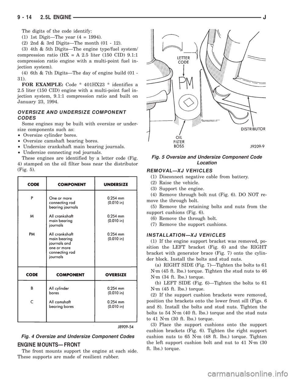
These engines are identified by a letter code (Fig.
4) stamped on the oil filter boss near the distributor
(Fig. 5).
ENGINE MOUNTSÐFRONT
The front mounts support the engine at each side.
These supports are made of resilient rubber.
REMOVALÐXJ VEHICLES
(1) Disconnect negative cable from battery.
(2) Raise the vehicle.
(3) Support the engine.
(4) Remove through bolt nut (Fig. 6). DO NOT re-
move the through bolt.
(5) Remove the retaining bolts and nuts from the
support cushions (Fig. 6).
(6) Remove the through bolt.
(7) Remove the support cushions.
INSTALLATIONÐXJ VEHICLES
(1) If the engine support bracket was removed, po-
sition the LEFT bracket (Fig. 6) and the RIGHT
bracket with generator brace (Fig. 7) onto the cylin-
der block. Install the bolts and stud nuts.
(a) RIGHT SIDE (Fig. 7)ÐTighten the bolts to 61
Nzm (45 ft. lbs.) torque. Tighten the stud nuts to 46
Nzm (34 ft. lbs.) torque.
(b) LEFT SIDE (Fig. 6)ÐTighten the bolts to 61
Nzm (45 ft. lbs.) torque.
(2) If the support cushion brackets were removed,
position the brackets onto the lower front sill (Figs. 6
and 8). Install the bolts and stud nuts. Tighten the
bolts to 54 Nzm (40 ft. lbs.) torque and the stud nuts
to 41 Nzm (30 ft. lbs.) torque.
(3) Place the support cushions onto the support
cushion brackets (Fig. 6). Tighten the right support
cushion nuts to 65 Nzm (48 ft. lbs.) torque. Tighten
the left support cushion bolt and nut to 41 Nzm (30
ft. lbs.) torque.
Fig. 4 Oversize and Undersize Component Codes
Fig. 5 Oversize and Undersize Component Code
Location
9 - 14 2.5L ENGINEJ
Page 1309 of 2158
at the engine cylinder head. Also tap the top of the
retainer to seat the valve locks.
(8) Install the engine cylinder head.
VALVE TIMING
Disconnect the spark plug wires and remove the
spark plugs.
Remove the engine cylinder head cover.
Remove the capscrews, bridge and pivot assembly,
and rocker arms from above the No.1 cylinder.
Alternately loosen each capscrew, one turn at a
time, to avoid damaging the bridge.
Rotate the crankshaft until the No.4 piston is at
top dead center (TDC) on the compression stroke.
Rotate the crankshaft counterclockwise (viewed
from the front of the engine) 90É.
Install a dial indicator on the end of the No.1 cyl-
inder intake valve push rod. Use rubber tubing to se-
cure the indicator stem on the push rod.
Set the dial indicator pointer at zero.
Rotate the crankshaft clockwise (viewed from the
front of the engine) until the dial indicator pointer
indicates 0.305 mm (0.012 inch) travel distance (lift).
The timing notch index on the vibration damper
should be aligned with the TDC mark on the timing
degree scale.
If the timing notch is more than 13 mm (1/2 inch)
away from the TDC mark in either direction, the
valve timing is incorrect.
If the valve timing is incorrect, the cause may be a
broken camshaft pin. It is not necessary to replace
the camshaft because of pin failure. A spring pin is
available for service replacement.
VIBRATION DAMPER
REMOVAL
(1) Disconnect negative cable from battery.
(2) Remove the serpentine drive belt and fan
shroud.
(3) Remove the vibration damper retaining bolt
and washer.
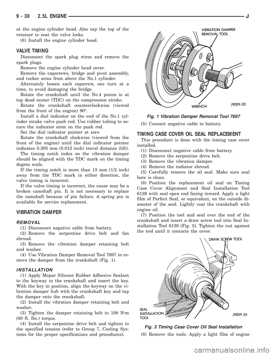
(4) Use Vibration Damper Removal Tool 7697 to re-
move the damper from the crankshaft (Fig. 1).
INSTALLATION
(1) Apply Mopar Silicone Rubber Adhesive Sealant
to the keyway in the crankshaft and insert the key.
With the key in position, align the keyway on the vi-
bration damper hub with the crankshaft key and tap
the damper onto the crankshaft.
(2) Install the vibration damper retaining bolt and
washer.
(3) Tighten the damper retaining bolt to 108 Nzm
(80 ft. lbs.) torque.
(4) Install the serpentine drive belt and tighten to
the specified tension (refer to Group 7, Cooling Sys-
tems for the proper specifications and procedures).(5) Connect negative cable to battery.
TIMING CASE COVER OIL SEAL REPLACEMENT
This procedure is done with the timing case cover
installed.
(1) Disconnect negative cable from battery.
(2) Remove the serpentine drive belt.
(3) Remove the vibration damper.
(4) Remove the radiator shroud.
(5) Carefully remove the oil seal. Make sure seal
bore is clean.
(6) Position the replacement oil seal on Timing
Case Cover Alignment and Seal Installation Tool
6139 with seal open end facing inward. Apply a light
film of Perfect Seal, or equivalent, on the outside di-
ameter of the seal. Lightly coat the crankshaft with
engine oil.
(7) Position the tool and seal over the end of the
crankshaft and insert a draw screw tool into Seal In-
stallation Tool 6139 (Fig. 3). Tighten the nut against
the tool until it contacts the cover.
(8) Remove the tools. Apply a light film of engine
Fig. 1 Vibration Damper Removal Tool 7697
Fig. 3 Timing Case Cover Oil Seal Installation
9 - 30 2.5L ENGINEJ
Page 1335 of 2158
The digits of the code identify:
(1) 1st DigitÐThe year (4 = 1994).
(2) 2nd & 3rd DigitsÐThe month (01 - 12).
(3) 4th & 5th DigitsÐThe engine type/fuel system/
compression ratio (MX = A 4.0 Liter (242 CID) 8.7:1
compression ratio engine with a multi-point fuel in-
jection system).
(4) 6th & 7th DigitsÐThe day of engine build (01 -
31).
FOR EXAMPLE:Code * 401MX12 * identifies a
4.0 Liter (242 CID) engine with a multi-point fuel in-
jection system, 8.7:1 compression ratio and built on
January 12, 1994.
OVERSIZE AND UNDERSIZE COMPONENT
CODES
Some engines may be built with oversize or under-
size components such as:
²Oversize cylinder bores.
²Oversize camshaft bearing bores.
²Undersize crankshaft main bearing journals.
²Undersize connecting rod journals.
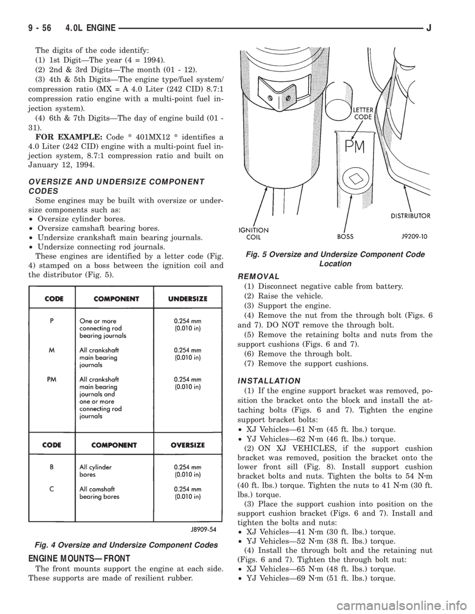
These engines are identified by a letter code (Fig.
4) stamped on a boss between the ignition coil and
the distributor (Fig. 5).
ENGINE MOUNTSÐFRONT
The front mounts support the engine at each side.
These supports are made of resilient rubber.
REMOVAL
(1) Disconnect negative cable from battery.
(2) Raise the vehicle.
(3) Support the engine.
(4) Remove the nut from the through bolt (Figs. 6
and 7). DO NOT remove the through bolt.
(5) Remove the retaining bolts and nuts from the
support cushions (Figs. 6 and 7).
(6) Remove the through bolt.
(7) Remove the support cushions.
INSTALLATION
(1) If the engine support bracket was removed, po-
sition the bracket onto the block and install the at-
taching bolts (Figs. 6 and 7). Tighten the engine
support bracket bolts:
²XJ VehiclesÐ61 Nzm (45 ft. lbs.) torque.
²YJ VehiclesÐ62 Nzm (46 ft. lbs.) torque.
(2) ON XJ VEHICLES, if the support cushion
bracket was removed, position the bracket onto the
lower front sill (Fig. 8). Install support cushion
bracket bolts and nuts. Tighten the bolts to 54 Nzm
(40 ft. lbs.) torque. Tighten the nuts to 41 Nzm (30 ft.
lbs.) torque.
(3) Place the support cushion into position on the
support cushion bracket (Figs. 6 and 7). Install and
tighten the bolts and nuts:
²XJ VehiclesÐ41 Nzm (30 ft. lbs.) torque.
²YJ VehiclesÐ52 Nzm (38 ft. lbs.) torque.
(4) Install the through bolt and the retaining nut
(Figs. 6 and 7). Tighten the through bolt nut:
²XJ VehiclesÐ65 Nzm (48 ft. lbs.) torque.
²YJ VehiclesÐ69 Nzm (51 ft. lbs.) torque.
Fig. 4 Oversize and Undersize Component Codes
Fig. 5 Oversize and Undersize Component Code
Location
9 - 56 4.0L ENGINEJ
Page 1350 of 2158
ments differ by more than 0.0635 mm (0.0025 in.),
ream the guide bore to accommodate an oversize
valve stem.
(7) Compare the measured valve guide bore diam-
eter with specifications (7.95-7.97 mm or 0.313-0.314
inch). If the measurement differs from specification
by more than 0.076 mm (0.003 inch), ream the guide
bore to accommodate an oversize valve stem.
ALTERNATIVE METHOD:
(1) Use a dial indicator to measure the lateral
movement of the valve stem (stem-to-guide clear-
ance). This must be done with the valve installed in
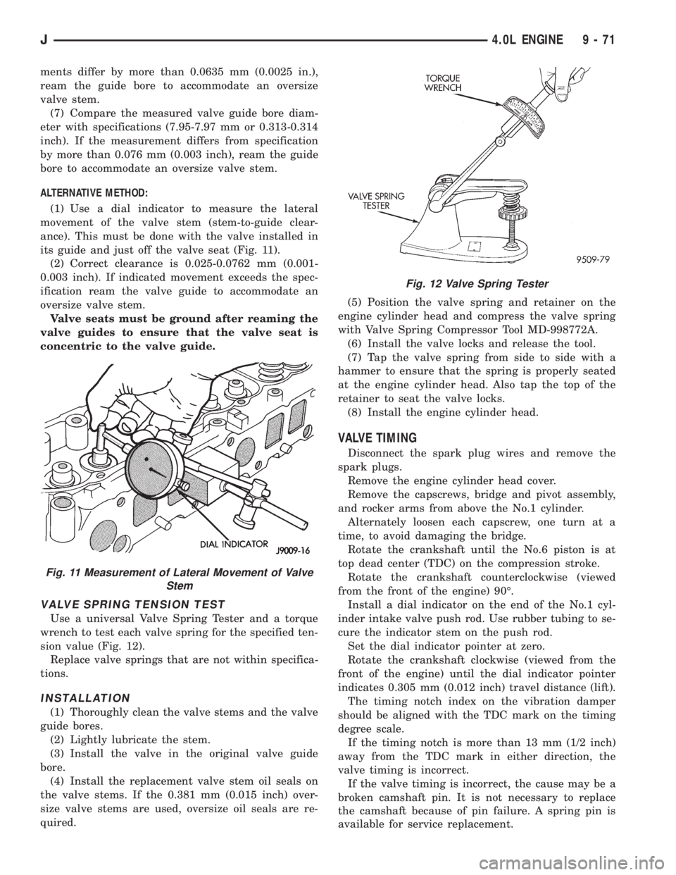
its guide and just off the valve seat (Fig. 11).
(2) Correct clearance is 0.025-0.0762 mm (0.001-
0.003 inch). If indicated movement exceeds the spec-
ification ream the valve guide to accommodate an
oversize valve stem.
Valve seats must be ground after reaming the
valve guides to ensure that the valve seat is
concentric to the valve guide.
VALVE SPRING TENSION TEST
Use a universal Valve Spring Tester and a torque
wrench to test each valve spring for the specified ten-
sion value (Fig. 12).
Replace valve springs that are not within specifica-
tions.
INSTALLATION
(1) Thoroughly clean the valve stems and the valve
guide bores.
(2) Lightly lubricate the stem.
(3) Install the valve in the original valve guide
bore.
(4) Install the replacement valve stem oil seals on
the valve stems. If the 0.381 mm (0.015 inch) over-
size valve stems are used, oversize oil seals are re-
quired.(5) Position the valve spring and retainer on the
engine cylinder head and compress the valve spring
with Valve Spring Compressor Tool MD-998772A.
(6) Install the valve locks and release the tool.
(7) Tap the valve spring from side to side with a
hammer to ensure that the spring is properly seated
at the engine cylinder head. Also tap the top of the
retainer to seat the valve locks.
(8) Install the engine cylinder head.
VALVE TIMING
Disconnect the spark plug wires and remove the
spark plugs.
Remove the engine cylinder head cover.
Remove the capscrews, bridge and pivot assembly,
and rocker arms from above the No.1 cylinder.
Alternately loosen each capscrew, one turn at a
time, to avoid damaging the bridge.
Rotate the crankshaft until the No.6 piston is at
top dead center (TDC) on the compression stroke.
Rotate the crankshaft counterclockwise (viewed
from the front of the engine) 90É.
Install a dial indicator on the end of the No.1 cyl-
inder intake valve push rod. Use rubber tubing to se-
cure the indicator stem on the push rod.
Set the dial indicator pointer at zero.
Rotate the crankshaft clockwise (viewed from the
front of the engine) until the dial indicator pointer
indicates 0.305 mm (0.012 inch) travel distance (lift).
The timing notch index on the vibration damper
should be aligned with the TDC mark on the timing
degree scale.
If the timing notch is more than 13 mm (1/2 inch)
away from the TDC mark in either direction, the
valve timing is incorrect.
If the valve timing is incorrect, the cause may be a
broken camshaft pin. It is not necessary to replace
the camshaft because of pin failure. A spring pin is
available for service replacement.
Fig. 11 Measurement of Lateral Movement of Valve
Stem
Fig. 12 Valve Spring Tester
J4.0L ENGINE 9 - 71
Page 1455 of 2158
line. However, these could result in a rich or lean
condition causing an oxygen sensor DTC to be stored
in the PCM.
Secondary Ignition Circuit:The PCM cannot
detect an inoperative ignition coil, fouled or worn
spark plugs, ignition cross firing, or open circuited
spark plug cables.
Engine Timing:The PCM cannot detect an incor-
rectly indexed timing chain, camshaft sprocket or
crankshaft sprocket. The PCM also cannot detect an
incorrectly indexed distributor. However, these could
result in a rich or lean condition causing an oxygen
sensor DTC to be stored in the PCM.
Cylinder Compression:The PCM cannot detect
uneven, low, or high engine cylinder compression.
Exhaust System:The PCM cannot detect a
plugged, restricted or leaking exhaust system.
Fuel Injector Malfunctions:The PCM cannot de-
termine if the fuel injector is clogged, or the wrong
injector is installed. However, these could result in a
rich or lean condition causing an oxygen sensor DTC
to be stored in the PCM.
Excessive Oil Consumption:Although the PCM
monitors exhaust stream oxygen content through ox-
ygen sensor (closed loop), it cannot determine exces-
sive oil consumption.
Throttle Body Air Flow:The PCM cannot detect
a clogged or restricted air cleaner inlet or air cleaner
element.
Evaporative System:The PCM will not detect a
restricted, plugged or loaded EVAP canister.
Vacuum Assist:Leaks or restrictions in the vac-
uum circuits of vacuum assisted engine control sys-
tem devices are not monitored by the PCM. However,
a vacuum leak at the MAP sensor will be monitored
and a diagnostic trouble code (DTC) will be gener-
ated by the PCM.
Powertrain Control Module (PCM) System
Ground:The PCM cannot determine a poor system
ground. However, a DTC may be generated as a re-
sult of this condition.
Powertrain Control Module (PCM) Connector
Engagement:The PCM cannot determine spread or
damaged connector pins. However, a DTC may be
generated as a result of this condition.
HIGH AND LOW LIMITS
The powertrain control module (PCM) compares in-
put signal voltages from each input device. It will es-
tablish high and low limits that are programmed into
it for that device. If the input voltage is not within
specifications and other Diagnostic Trouble Code
(DTC) criteria are met, a DTC will be stored in mem-
ory. Other DTC criteria might include engine rpm
limits or input voltages from other sensors or
switches. The other inputs might have to be sensed
by the PCM when it senses a high or low input volt-
age from the control system device in question.
ACCESSING DIAGNOSTIC TROUBLE CODES
A stored diagnostic trouble code (DTC) can be dis-
played by cycling the ignition key On-Off-On-Off-On
within three seconds and observing the malfunction
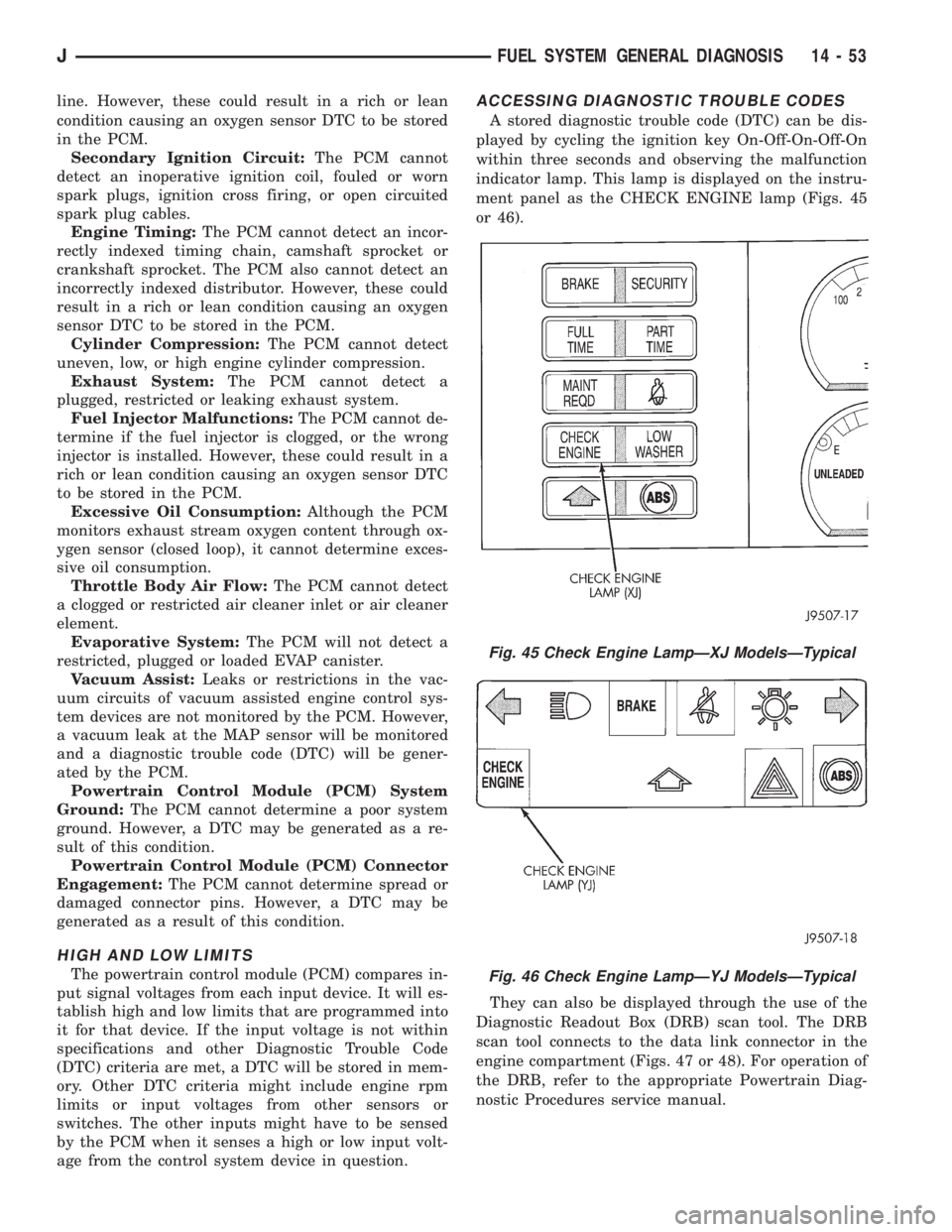
indicator lamp. This lamp is displayed on the instru-
ment panel as the CHECK ENGINE lamp (Figs. 45
or 46).
They can also be displayed through the use of the
Diagnostic Readout Box (DRB) scan tool. The DRB
scan tool connects to the data link connector in the
engine compartment (Figs. 47 or 48). For operation of
the DRB, refer to the appropriate Powertrain Diag-
nostic Procedures service manual.
Fig. 45 Check Engine LampÐXJ ModelsÐTypical
Fig. 46 Check Engine LampÐYJ ModelsÐTypical
JFUEL SYSTEM GENERAL DIAGNOSIS 14 - 53