1995 JEEP YJ fuse chart
[x] Cancel search: fuse chartPage 370 of 2158

(2) Disconnect battery negative cable. Remove in-
strument cluster bezel and cluster assembly. Unplug
cluster connector A. Connect battery negative cable.
Turn headlamps on and select high beam. Check for
battery voltage at cavity A4 of cluster connector A. If
OK, replace indicator bulb. If not OK, repair circuit
to headlamp dimmer (multi-function) switch as re-
quired.
LOW FUEL WARNING LAMP
(1) Check that fuel gauge is operating as designed.
See Fuel Gauge Calibration chart in Specifications. If
OK, go to next step. If not OK, see Fuel Gauge in
this section for diagnosis.
(2) With at least 10 gallons of fuel in fuel tank, un-
plug fuel tank sending unit connector. Turn ignition
switch to ON and wait 10 seconds. Lamp (LED)
should light. Reconnect fuel tank sending unit and
wait 20 seconds. Lamp (LED) should go off. If not
OK, replace low fuel warning lamp module.
LOW OIL PRESSURE WARNING LAMP
The diagnosis found here addresses an inoperative
lamp condition. If the problem being diagnosed is re-
lated to lamp accuracy, be certain to confirm that
problem is with lamp and not with engine oiling sys-
tem. Actual engine oil pressure should be checked
with a test gauge before you proceed with lamp diag-
nosis. Refer to Group 9 - Engines for more informa-
tion.
(1) Turn ignition switch to ON. Lamp should light.
Start engine. Lamp should go off. If not OK, turn en-
gine off and go to next step.
(2) Unplug connector at oil pressure switch (Fig.
3). The switch is located on right side of engine block.
On 2.5L engine, it is just forward of ignition distrib-
utor and just to the rear of generator mounting
bracket. On 4.0L engine, it is just to the rear of igni-
tion distributor and above oil filter adapter. Install a
jumper wire from connector to a good ground. Turn
ignition switch to ON. Lamp should light. Unplug
jumper wire. Lamp should go out. If OK, replace oil
pressure switch. If not OK, go to next step.
(3) Turn ignition switch to OFF. Disconnect battery
negative cable. Remove instrument cluster bezel and
cluster assembly. Install a jumper wire from cavity
B7 (cavity B8 - RHD) of cluster connector A to a good
ground. Connect battery negative cable and turn ig-
nition switch to ON. Lamp should light. If OK, go to
next step. If not OK, replace lamp bulb.
(4) Turn ignition switch to OFF. Disconnect battery
negative cable. Unplug instrument cluster connector
A. Check continuity between cavity B7 (cavity B8 -
RHD) of cluster connector A and a good ground.
There should be no continuity. If OK, go to next step.
If not OK, repair short circuit as required.
(5) Check continuity between cavity B7 (cavity B8
- RHD) of cluster connector A and oil pressure switchconnector. There should be continuity. If not OK, re-
pair open circuit as required.
LOW WASHER FLUID WARNING LAMP
(1) Unplug washer fluid level switch connector.
Turn ignition switch to ON. Check for battery voltage
at connector cavity A. If OK, turn ignition switch to
OFF and go to next step. If not OK, repair open cir-
cuit to fuse F6 in PDC.
(2) Install a jumper wire from cavity A to cavity B
of washer fluid level switch connector. Turn ignition
switch to ON. Lamp should light. Unplug jumper and
lamp should go OFF. If OK, replace washer fluid
level switch. If not OK, go to next step.
(3) Turn ignition switch to OFF. Disconnect battery
negative cable. Remove instrument cluster bezel and
cluster assembly. Unplug instrument cluster (tell-
tale) connector B. Check continuity between cavity 16
(cavity 1 - RHD) of cluster connector B and a good
ground. There should be continuity. If OK, plug clus-
ter connector B back into cluster and go to next step.
If not OK, repair open circuit to ground as required.
(4) Connect battery negative cable. Install a
jumper wire from a 12-volt battery feed to cavity 1
(cavity 16 - RHD) of cluster connector B. Lamp
should light. If OK, go to next step. If not OK, re-
place bulb.
(5) Disconnect battery negative cable. Unplug clus-
ter connector B. Check continuity between cavity 1
(cavity 16 - RHD) of cluster connector B and a good
ground. There should be no continuity. If OK, go to
next step. If not OK, repair short circuit to switch as
required.
(6) Check continuity between cavity 1 (cavity 16 -
RHD) of cluster connector B and cavity B of washer
fluid level switch connector. There should be continu-
ity. If not OK, repair open circuit to switch as re-
quired.
MALFUNCTION INDICATOR LAMP
The diagnosis found here addresses an inoperative
lamp condition. If the lamp comes on and stays on
with engine running, refer to Group 14 - Fuel System
for diagnosis. If no fuel or emission system problem
is found, the following procedure will help locate a
short or open in the lamp circuit.
(1) Disconnect battery negative cable. Unplug PCM
connector. Install a jumper wire from cavity 32 of
PCM connector (Fig. 5) to a good ground. Connect
battery negative cable. Turn ignition switch to ON.
Lamp should light. Remove jumper wire and lamp
should go OFF. If OK, refer to Powertrain Diagnostic
Procedures to check PCM. If not OK, go to next step.
(2) Turn ignition switch to OFF. Disconnect battery
negative cable. Remove instrument cluster bezel and
cluster assembly. Install a jumper wire from cavity 2
(cavity 15 - RHD) of cluster (tell-tale) connector B to
a good ground. Connect battery negative cable. Turn
8E - 14 INSTRUMENT PANEL AND GAUGESÐXJJ
Page 402 of 2158

ANTENNA
All models use a fixed-length stainless steel rod-
type antenna mast, installed at the right front (fend-
er on XJ, cowl side on YJ) of the vehicle. The
antenna mast is connected to the center wire of the
coaxial antenna cable and is not grounded to any
part of the vehicle.
To eliminate static, the antenna base must have a
good ground. The coaxial antenna cable shield (the
outer wire mesh of the cable) is grounded to the an-
tenna base and the radio chassis.
The factory installed ETRs automatically compen-
sate for radio antenna trim. Therefore, no antenna
trimmer adjustment is required or possible when re-
placing the receiver or the antenna.
RADIO NOISE SUPPRESSION
Radio Frequency Interference (RFI) and Electro-
Magnetic Interference (EMI) noise suppression is ac-
complished primarily through circuitry internal to
the radio receivers. These internal suppression de-
vices are only serviced as a part of the radio receiver.External suppression devices that are serviceable
and should be checked in the case of RFI or EMI
noise complaints include the following:
²radio antenna base ground
²engine-to-body ground strap
²resistor-type spark plugs
²radio suppression-type secondary ignition wiring.
In addition, if the source of RFI or EMI noise is
identified as a component on the vehicle (i.e.:genera-
tor, blower motor, etc.), the ground path for that com-
ponent should be checked. If excessive resistance is
found in that circuit, repair as required before con-
sidering any component replacement.
Fleet vehicles are available with an extra-cost RFI-
suppressed Powertrain Control Module (PCM). This
unit reduces interference generated by the PCM on
some radio frequencies used in two-way radio com-
munications. However, this unit will not resolve com-
plaints of RFI in the commercial AM or FM radio
frequency ranges.
DIAGNOSIS
RADIO
CAUTION: Do not operate the radio with speaker
leads detached since damage to the transistors
may result.
(1) Check fuse 2 in fuseblock module and fuse in
back of radio chassis. If OK, go to next step. If not
OK, replace fuse.
(2) Turn ignition switch to ON position. Check for
battery voltage at fuse 2. If OK, go to next step. If
not OK, repair circuit to ignition switch as required.
(3) Turn ignition switch to OFF position. Discon-
nect battery negative cable. Remove instrument clus-
ter bezel. Remove radio, but do not unplug any
connections. Check for continuity between the radio
chassis and a good ground. There should be continu-
ity. If OK, go to next step. If not OK, repair radio
ground circuit as required.
(4) Connect battery negative cable. Turn ignition
switch to ON position. See Radio Connections chart.
Check for battery voltage at cavity 3 of radio connec-
tor. If OK, go to next step. If not OK, repair circuit to
fuse 2 as required.
(5) Turn ignition switch to OFF position. Check for
battery voltage at cavity 4 of radio connector. If OK,
replace radio. If not OK, repair circuit to IOD fuse in
PDC as required.
SPEAKERS
CAUTION: Do not operate the radio with speaker
leads detached since damage to the transistors
may result.
(1) Turn radio on and adjust balance and fader
controls to check performance of each individual
speaker. Note the speaker locations that are not per-
forming correctly. Go to next step.
(2) Turn radio off. Disconnect battery negative ca-
ble. Remove instrument cluster bezel and remove ra-
dio. See Radio Connections chart. Check both the
speaker feed and return cavities at radio for continu-
ity to a good ground. There should be no continuity.
If OK, go to next step. If not OK, repair wiring cir-
cuit as required.
(3) Check resistance between speaker feed and re-
turn cavities. Meter should read between 3 and 8
ohms (speaker impedance). If OK, see diagnosis for
Radio. If not OK, go to next step.
(4) Unplug speaker wiring connector. Check for
continuity between speaker feed cavity at radio and
at speaker. Repeat check between speaker return
cavity at radio and at speaker. If OK, replace
speaker. If not OK, repair wiring circuit as required.
8F - 2 AUDIO SYSTEMSJ
Page 422 of 2158
SPEED CONTROL SWITCH
WARNING: ON VEHICLES EQUIPPED WITH AN AIR-
BAG, REFER TO GROUP 8M - RESTRAINT SYS-
TEMS BEFORE ATTEMPTING STEERING WHEEL
COMPONENT DIAGNOSIS OR SERVICE. FAILURE
TO TAKE PROPER PRECAUTIONS COULD RESULT
IN ACCIDENTAL AIRBAG DEPLOYMENT AND POS-
SIBLE PERSONAL INJURY.
(1) Disconnect battery negative cable. Remove
speed control switch from steering wheel.
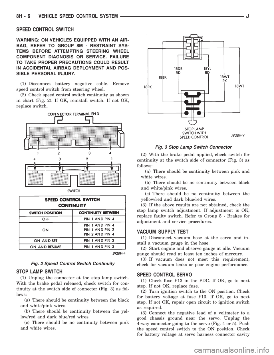
(2) Check speed control switch continuity as shown
in chart (Fig. 2). If OK, reinstall switch. If not OK,
replace switch.
STOP LAMP SWITCH
(1) Unplug the connector at the stop lamp switch.
With the brake pedal released, check switch for con-
tinuity at the switch side of connector (Fig. 3) as fol-
lows:
(a) There should be continuity between the black
and white/pink wires.
(b) There should be continuity between the yel-
low/red and dark blue/red wires.
(c) There should be no continuity between pink
and white wires.(2) With the brake pedal applied, check switch for
continuity at the switch side of connector (Fig. 3) as
follows:
(a) There should be continuity between pink and
white wires.
(b) There should be no continuity between black
and white/pink wires.
(c) There should be no continuity between the
yellow/red and dark blue/red wires.
(3) If the above results are not obtained, check the
stop lamp switch adjustment. If adjustment is OK,
replace faulty switch. Refer to Group 5 - Brakes for
adjustment and service procedures.
VACUUM SUPPLY TEST
(1) Disconnect vacuum hose at the servo and in-
stall a vacuum gauge in the hose.
(2) Start engine and observe gauge at idle. Vacuum
gauge should read at least ten inches of mercury.
(3) If vacuum does not meet this requirement,
check for vacuum leaks or poor engine performance.
SPEED CONTROL SERVO
(1) Check fuse F13 in the PDC. If OK, go to next
step. If not OK, replace fuse.
(2) Turn ignition switch to the ON position. Check
for battery voltage at fuse F13. If OK, go to next
step. If not OK, repair open circuit to ignition switch
as required.
(3) Connect the negative lead of a voltmeter to a
good chassis ground near the servo. Unplug the
4-way connector going to the servo (Fig. 4 or 5). Push
the speed control switch to the ON position. Check
for battery voltage at servo harness connector cavity
Fig. 2 Speed Control Switch Continuity
Fig. 3 Stop Lamp Switch Connector
8H - 6 VEHICLE SPEED CONTROL SYSTEMJ
Page 430 of 2158
lamps and repair circuits or replace bulbs as re-
quired. If system still does not function properly, pro-
ceed as follows.
(1) Locate fuseblock module under driver's side of
instrument panel. Remove and inspect fuse 4. If OK,
go to next step. If not OK, replace fuse as required.
(2) Replace turn signal flasher (light blue can in
fuseblock module) with a known good unit. Test op-
eration. If OK, replace faulty turn signal flasher. If
not OK, remove test flasher and go to next step.
(3) Turn ignition switch to ACCESSORY position.
Check for battery voltage at flasher cavity on left
(closest to hazard flasher). If OK, go to next step. If
not OK, repair circuit to fuse 4 as required.
(4) Turn ignition switch to OFF position. See Turn
Signal/Hazard Warning Switch Remove/Install to lo-
cate steering column connector. Unplug connector.
(5) Turn ignition switch to ACCESSORY position.
Check for battery voltage at connector terminal L. If
OK, replace turn signal/hazard warning switch. If not
OK, repair circuit between turn signal flasher and
steering column connector.
HAZARD WARNING SYSTEM - YJ
(1) Locate Power Distribution Center (PDC) near
battery tray in engine compartment. Remove and in-
spect fuse F5. If OK, go to next step. If not OK,
replace fuse as required.(2) Replace hazard warning flasher (metal can in
fuseblock module) with a known good unit. Test op-
eration. If OK, replace faulty hazard warning flasher.
If not OK, remove test flasher and go to next step.
(3) Check for battery voltage at flasher cavity on
left (closest to hazard flasher). If OK, go to next step.
If not OK, repair circuit to fuse F5 in PDC as re-
quired.
(4) See Turn Signal/Hazard Warning Switch Re-
move/Install to locate steering column connector. Un-
plug connector.
(5) Check for battery voltage at connector terminal
K. If OK, replace turn signal/hazard warning switch.
If not OK, repair circuit between hazard warning
flasher and steering column connector.
MULTI-FUNCTION SWITCH - XJ
(1) Access multi-function switch connector and re-
move. See service procedures for Multi-Function
Switch, in this group.
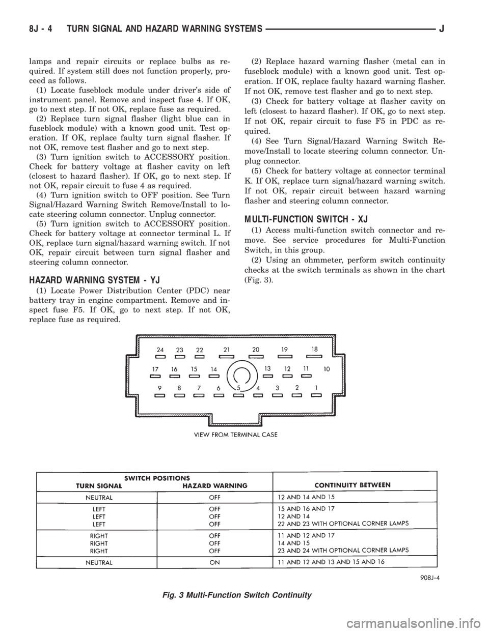
(2) Using an ohmmeter, perform switch continuity
checks at the switch terminals as shown in the chart
(Fig. 3).
Fig. 3 Multi-Function Switch Continuity
8J - 4 TURN SIGNAL AND HAZARD WARNING SYSTEMSJ
Page 438 of 2158

WINDSHIELD WASHER SYSTEM
WITH NON-INTERMITTENT WIPE
(1) Unplug washer pump connector. Measure resis-
tance between terminal B at pump and a clean chas-
sis ground. Meter should read zero ohms. If not OK,
repair open to ground.
(2) Turn ignition switch to ACCESSORY and
washer (multi-function) switch to ON.
(a) Measure voltage at washer pump connector
terminal A. Meter should read battery voltage. If
OK, replace washer pump. If not OK, go to next
step.
(b) Measure voltage at wiper/washer switch con-
nector terminal B. Meter should read battery volt-
age. If OK, repair open to washer pump. If not OK,
replace switch.
WITH INTERMITTENT WIPE
(1) Unplug washer pump connector. Measure resis-
tance between terminal B at pump and a clean chas-
sis ground. Meter should read zero ohms. If not OK,
repair open to ground.
(2) Turn ignition switch to ACCESSORY and
washer (multi-function) switch to ON.
(a) Measure voltage at intermittent wipe module
switch connector terminal B (pink wire). Meter
should read battery voltage. If not OK, replace
wiper switch.
(b) Measure voltage at wipe module motor con-
nector terminal B (brown wire). Meter should read
battery voltage. If not OK, replace module.
(c) Measure voltage at washer pump connector
terminal A at pump. Meter should read battery
voltage. If OK, replace pump. If not OK, repair
open from wipe module.
WINDSHIELD WIPER/WASHER SWITCH
Use an ohmmeter to test for continuity (no resis-
tance) between the terminals of the switch as shown
in the Multi-Function Switch Continuity chart (Fig. 2
or 3).
INTERMITTENT WIPE MODULE
The intermittent wipe module is non-serviceable.
Refer to Group 8W - Wiring Diagrams for more infor-
mation.
The intermittent wipe module is attached to the
lower instrument panel cover near the steering col-
umn with a hook and loop fastener patch.
LIFTGATE WIPER SYSTEM
(1) Remove and inspect fuse 1. Replace faulty fuse,
if required.
(2) Turn ignition switch to ACCESSORY and lift-
gate wiper switch to WASH.(a) Measure voltage at liftgate wiper switch ter-
minal B. Meter should read battery voltage. If not
OK, repair open to fuse 1.
(b) Measure voltage at liftgate wiper switch ter-
minals A, C and D. Meter should read battery volt-
age. If not OK, replace switch.
(3) Turn ignition switch to ACCESSORY, place lift-
gate wiper switch in WIPE. Measure voltage at lift-
Fig. 2 Multi-Function Switch Continuity (Two-Speed
Wipers)
Fig. 3 Multi-Function Switch Continuity (Intermittent
Wipe)
8K - 4 WIPER AND WASHER SYSTEMS - XJJ
Page 439 of 2158
gate wiper switch terminal C. Meter should read
battery voltage. If not OK, replace switch.
(4) Remove liftgate cover and measure resistance
from liftgate wiper motor terminal 1 to a good
ground. Meter should read zero ohms. If not OK, re-
pair open to ground splice.
(5) Turn ignition switch to ACCESSORY and lift-
gate wiper switch to WASH. Measure voltage at mo-
tor connector terminals 2, 3 and 4. Meter should read
battery voltage. If OK, replace wiper motor. If not
OK, repair open(s) to liftgate wiper switch.
LIFTGATE WASHER SYSTEM
(1) Turn ignition switch to ACCESSORY and place
liftgate wiper/washer switch in WASH. Operate lift-
gate wiper motor. If motor does not operate check
fuse 1. Replace faulty fuse, if required.
(2) Turn ignition switch to ACCESSORY and un-
plug liftgate washer pump connector.
(a) Measure resistance at pump connector termi-
nal B (ignition switch OFF). Meter should read
zero ohms. If not OK, repair open to ground.
(b) Measure voltage at pump connector terminal
A, switch in WASH. Meter should read battery
voltage. If OK, replace pump. If not OK, go to step
3.
(3) Remove switch and reconnect below instrument
panel. Backprobe switch connector with ignition
switch in ACCESSORY.
(a) Measure voltage at switch connector terminal
B. Meter should read battery voltage. If not OK, re-
pair open to fuse.
(b) Measure voltage at switch connector terminal
A, switch in WASH. Meter should read battery
voltage. If not OK, replace switch.
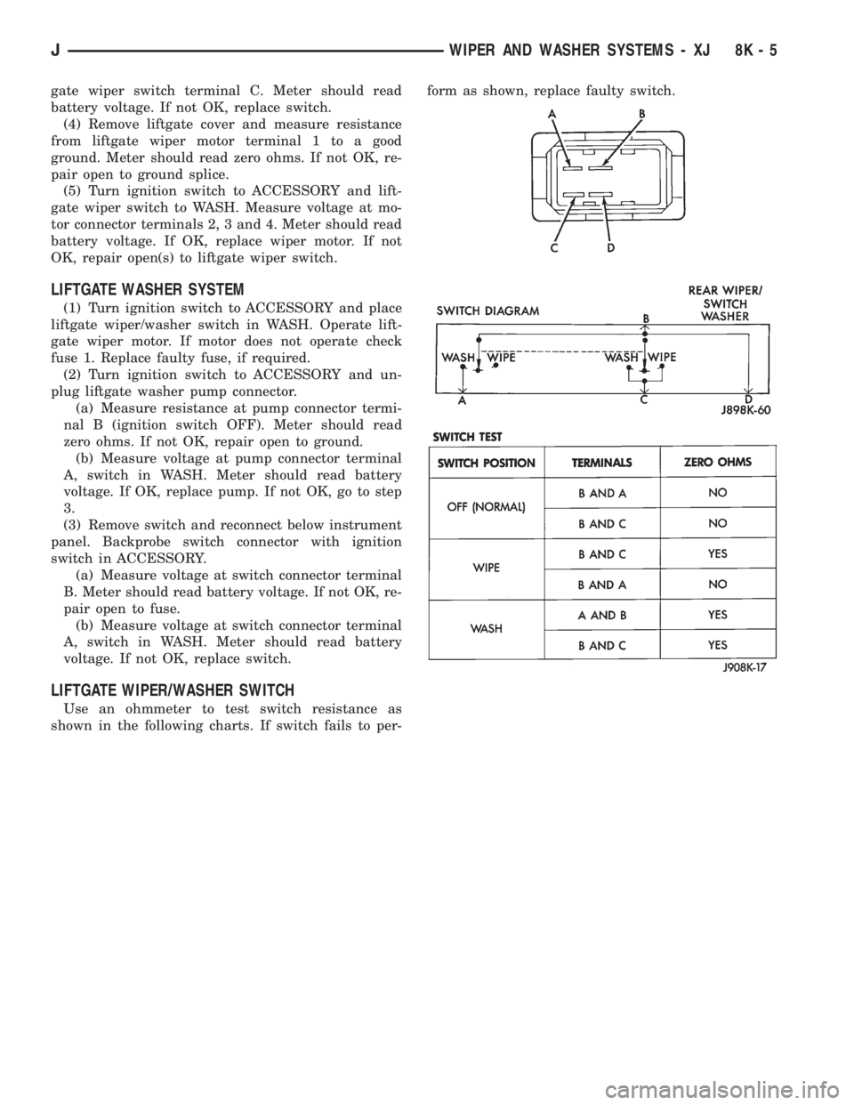
LIFTGATE WIPER/WASHER SWITCH
Use an ohmmeter to test switch resistance as
shown in the following charts. If switch fails to per-form as shown, replace faulty switch.
JWIPER AND WASHER SYSTEMS - XJ 8K - 5
Page 502 of 2158
DIAGNOSIS
As a preliminary system diagnosis, note system op-
eration while you actuate both the Lock and Unlock
functions with the power lock switches and the key-
less entry transmitter. Then, proceed as follows:
²If system fails to function with either the switches
or the transmitter, see Power Lock System diagnosis.
²If system functions with both switches, but not the
transmitter, see Keyless Entry Transmitter diagnosis.
²If system functions with transmitter, but not with
one or both switches, see Power Lock System diagno-
sis.
²If one lock fails to operate with the switches or
transmitter, see Power Lock Motor diagnosis.
POWER LOCK SYSTEM
(1) Inspect fuse 13 in fuseblock module. Replace if
necessary. If OK, measure voltage at battery side of
fuse. There should be 12 volts. If not OK, repair open
from Power Distribution Center.
(2) Remove door switch(es) and measure voltage at
terminal 1. Meter should read battery voltage. If OK,
go to next step. If not OK, repair open to fuse 9 in
fuseblock module.
(3) Check door switch continuity as shown in the
applicable charts on the following pages. If OK, go to
next step. If not OK, replace switch.
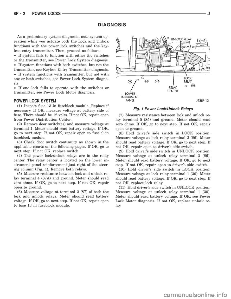
(4) The power lock/unlock relays are in the relay
center. The relay center is located on the lower in-
strument panel reinforcement just right of the steer-
ing column (Fig. 1). Remove both relays.
(5) Measure resistance between lock and unlock re-
lay terminal 4 (87A) and ground. Meter should read
zero ohms. If OK, go to next step. If not OK, repair
open to ground.
(6) Measure voltage at terminal 2 (87) of both the
lock and unlock relays. Meter should read battery
voltage. If OK, go to next step. If not OK, repair open
to fuse 13 in fuseblock module.(7) Measure resistance between lock and unlock re-
lay terminal 5 (85) and ground. Meter should read
zero ohms. If OK, go to next step. If not OK, repair
open to ground.
(8) Hold driver's side switch in LOCK position.
Measure voltage at lock relay terminal 3 (86). Meter
should read battery voltage. If OK, go to next step. If
not OK, repair open to driver's side switch.
(9) Hold driver's side switch in UNLOCK position.
Measure voltage at unlock relay terminal 3 (86).
Meter should read battery voltage. If OK, go to next
step. If not OK, repair open to driver's side switch.
(10) Hold driver's side switch in LOCK position.
Measure voltage at lock relay terminal 1 (30). Meter
should read battery voltage. If OK, go to next step. If
not OK, replace lock relay.
(11) Hold driver's side switch in UNLOCK position.
Measure voltage at unlock relay terminal 1 (30).
Meter should read battery voltage. If OK, see Power
Lock Motor diagnosis. If not OK, replace unlock re-
lay.Fig. 1 Power Lock/Unlock Relays
8P - 2 POWER LOCKSJ
Page 514 of 2158
DIAGNOSIS
Before any testing is attempted the battery should
be fully charged and all connections and pins cleaned
and tightened to ensure proper continuity and
grounds.
With the dome lamp on, apply switch in direction
of the failure. If the dome lamp dims, the seat may
be jamming. Check for binding or obstructions. If the
dome lamp does not dim, then proceed with the fol-
lowing electrical tests.
POWER SEAT ADJUSTER/MOTORS
Operate the power seat switch to move all three
seat motors. The seat should move in all directions.
If not OK, proceed as follows. If one or more motors
operate, see diagnosis for Power Seat Switch.
(1) Check circuit breaker 16 in the fuseblock mod-
ule. If OK, go to next step. If not OK, replace circuit
breaker.
(2) Remove switch mounting screws and check for
battery voltage at red wire at switch connector. If
OK, go to next step. If not OK, repair wiring to cir-
cuit breaker.(3) Check for continuity between black wire at
switch connector and a good ground. There should be
continuity. If OK, go to next step. If not OK, repair
wiring to ground.
(4) See diagnosis for Power Seat Switch. If switch
continuity checks OK, replace faulty motor/adjuster
assembly. If switch continuity is not OK, replace
faulty switch.
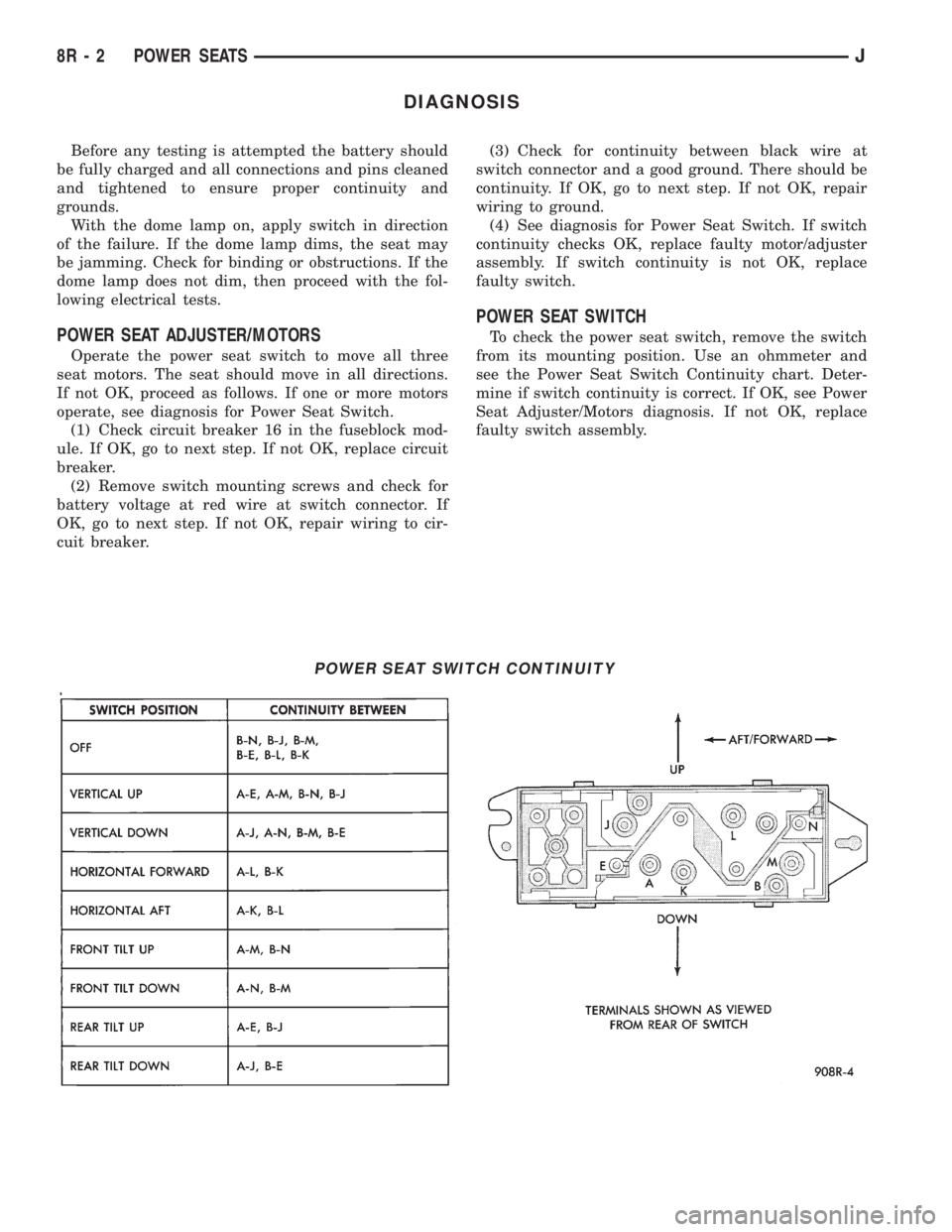
POWER SEAT SWITCH
To check the power seat switch, remove the switch
from its mounting position. Use an ohmmeter and
see the Power Seat Switch Continuity chart. Deter-
mine if switch continuity is correct. If OK, see Power
Seat Adjuster/Motors diagnosis. If not OK, replace
faulty switch assembly.
POWER SEAT SWITCH CONTINUITY
8R - 2 POWER SEATSJ