1995 JEEP YJ center console removal
[x] Cancel search: center console removalPage 322 of 2158

(4) With the degaussing tool still energized, slowly
back it away from the screw until the tool is at least
2 feet from the screw head, then unplug the tool.
(5) Place an 8-1/2 X 11 inch piece of paper, oriented
lengthwise from front to rear, on the center line of
the roof at the windshield header (Fig. 4). The pur-
pose of the paper is to protect the roof panel from
scratches and define the area to be demagnetized.
(6) Plug in the degaussing tool, while keeping the
tool at least 2 feet away from the compass unit.
(7) Slowly approach the center line of the roof
panel at the windshield header with the degaussing
tool plugged in.
(8) Contact the roof panel with the tip of the tool.
Be sure template is in place to avoid scratching the
roof panel. Using a slow, back and forth sweeping
motion and allowing 1/2-inch between passes (Fig. 4),
move the tool at least 4 inches either side of the roof
center line and 11 inches back from the windshield
header.
(9) With the degaussing tool still energized, slowly
back it away from the roof panel until the tip is at
least 2 feet from the roof. Then unplug the tool.
(10) Calibrate the compass and adjust variance as
described in this group.OVERHEAD CONSOLE REMOVE/INSTALL
(1) Remove screw forward of the compass unit (Fig.
5).
(2) Flex housing outward while pressing upward to
disengage the housing from the rear bracket (Arrow
1 in Fig. 5).
(3) Slide console rearward until the console de-
taches from the front mounting bracket (Arrow 2 in
Fig. 5).
(4) While pressing up on rear of console (Arrow 1
in Fig. 5), slide console forward, holding front away
from headliner (Arrow 2 in Fig. 5). Move console for-
ward until the rear detaches from headliner and be-
comes free (Fig. 6).
(5) Disconnect wire harnesses from keyless entry
and compass/thermometer modules (Figs. 7 and 8).
(6) Reverse removal procedures to install. Be sure
to flex housing outward near the keyless entry re-
ceiver until the console snaps onto the rear mounting
bracket.
Fig. 4 Roof Demagnetizing Pattern
Fig. 5 Remove/Install Overhead Console
Fig. 6 Remove/Install Overhead Console
8C - 6 OVERHEAD CONSOLEJ
Page 512 of 2158
(8) Reverse removal procedures to install. Be sure
to flex housing outward near the keyless entry mod-
ule until the console snaps onto the rear mounting
bracket.
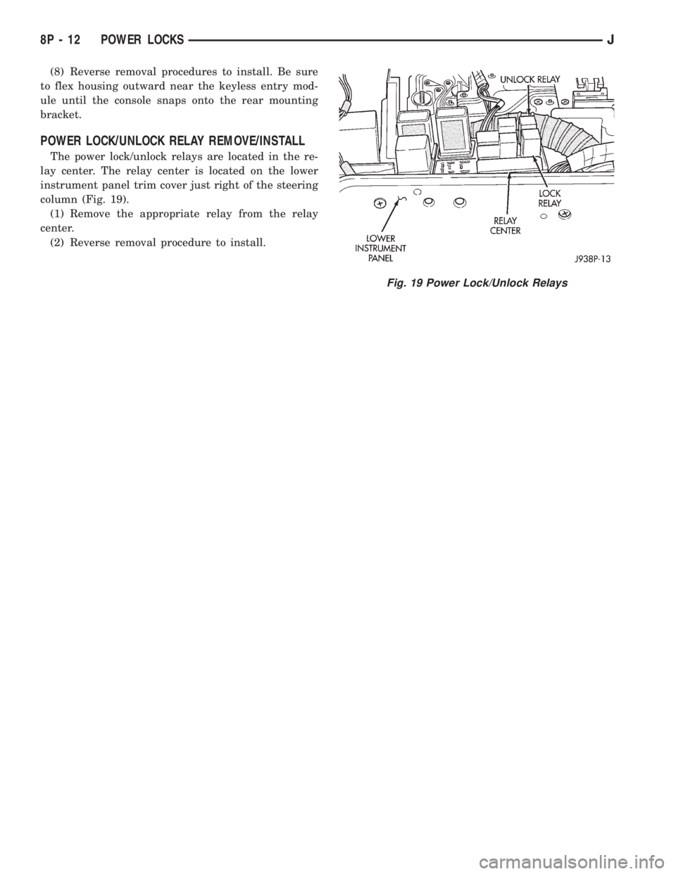
POWER LOCK/UNLOCK RELAY REMOVE/INSTALL
The power lock/unlock relays are located in the re-
lay center. The relay center is located on the lower
instrument panel trim cover just right of the steering
column (Fig. 19).
(1) Remove the appropriate relay from the relay
center.
(2) Reverse removal procedure to install.
Fig. 19 Power Lock/Unlock Relays
8P - 12 POWER LOCKSJ
Page 528 of 2158
SERVICE PROCEDURES
POWER MIRROR SWITCH REMOVE/INSTALL
(1) Disconnect battery negative cable.
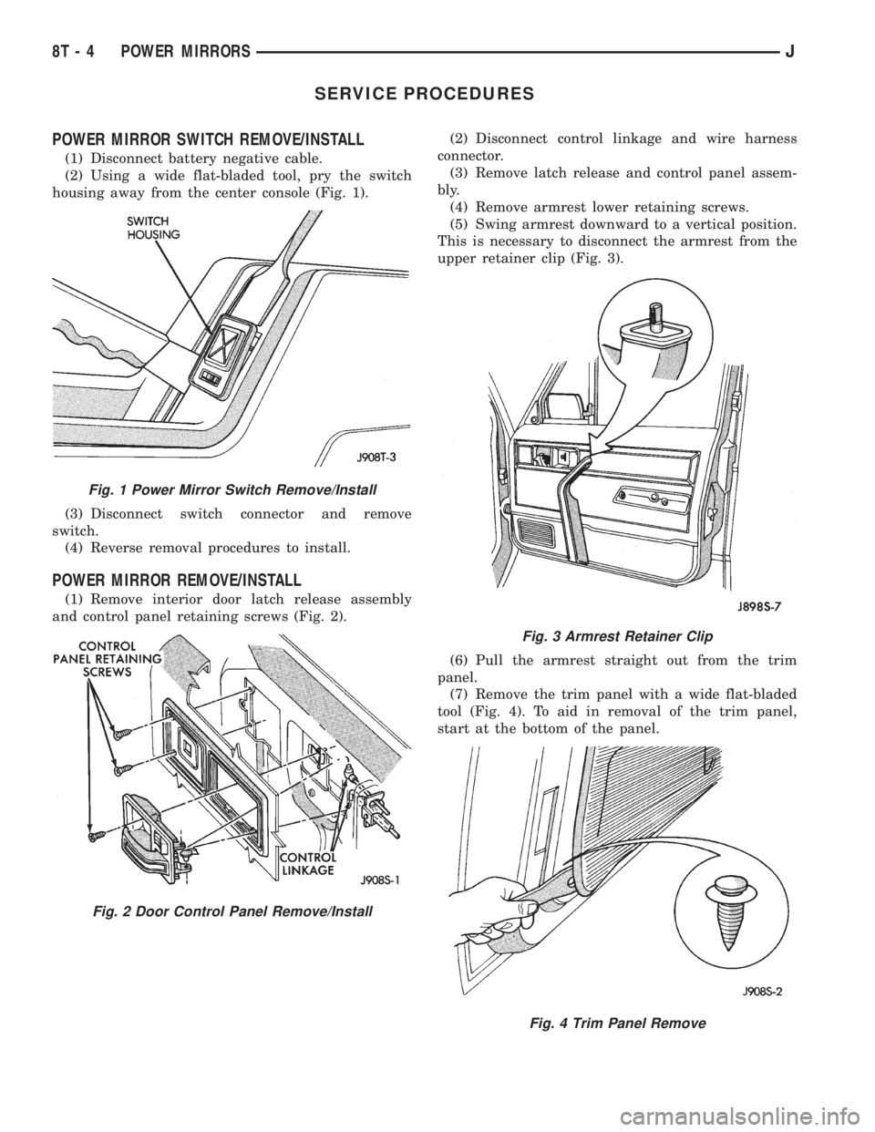
(2) Using a wide flat-bladed tool, pry the switch
housing away from the center console (Fig. 1).
(3) Disconnect switch connector and remove
switch.
(4) Reverse removal procedures to install.
POWER MIRROR REMOVE/INSTALL
(1) Remove interior door latch release assembly
and control panel retaining screws (Fig. 2).(2) Disconnect control linkage and wire harness
connector.
(3) Remove latch release and control panel assem-
bly.
(4) Remove armrest lower retaining screws.
(5) Swing armrest downward to a vertical position.
This is necessary to disconnect the armrest from the
upper retainer clip (Fig. 3).
(6) Pull the armrest straight out from the trim
panel.
(7) Remove the trim panel with a wide flat-bladed
tool (Fig. 4). To aid in removal of the trim panel,
start at the bottom of the panel.
Fig. 1 Power Mirror Switch Remove/Install
Fig. 2 Door Control Panel Remove/Install
Fig. 3 Armrest Retainer Clip
Fig. 4 Trim Panel Remove
8T - 4 POWER MIRRORSJ
Page 2106 of 2158
HEATER CORE
REVIEW WARNINGS AND CAUTIONS IN
THIS GROUP BEFORE PERFORMING THIS
OPERATION.
REMOVAL
(1) Drain the radiator.
(2) Disconnect heater hoses at heater core tubes.
(3) Remove heater/evaporator housing side cover.
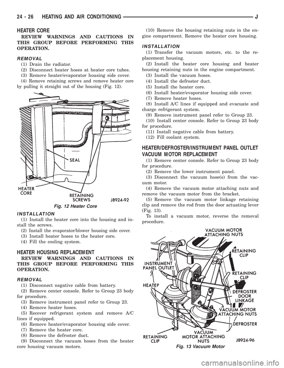
(4) Remove retaining screws and remove heater core
by pulling it straight out of the housing (Fig. 12).
INSTALLATION
(1) Install the heater core into the housing and in-
stall the screws.
(2) Install the evaporator/blower housing side cover.
(3) Install heater hoses to the heater core.
(4) Fill the cooling system.
HEATER HOUSING REPLACEMENT
REVIEW WARNINGS AND CAUTIONS IN
THIS GROUP BEFORE PERFORMING THIS
OPERATION.
REMOVAL
(1) Disconnect negative cable from battery.
(2) Remove center console. Refer to Group 23 body
for procedure.
(3) Remove instrument panel refer to Group 23.
(4) Remove heater hoses.
(5) Recover refrigerant system and remove A/C
lines if equipped.
(6) Remove heater/evaporator housing side cover.
(7) Remove the heater core.
(8) Remove the defroster duct.
(9) Disconnect the vacuum hoses from the heater
core housing vacuum motors.(10) Remove the housing retaining nuts in the en-
gine compartment. Remove the heater core housing.
INSTALLATION
(1) Transfer the vacuum motors, etc. to the re-
placement housing.
(2) Install the heater core housing and heater
housing retaining nuts in the engine compartment.
(3) Install the vacuum hoses.
(4) Install the defroster duct.
(5) Install the heater core.
(6) Install heater/evaporator housing side cover.
(7) Remove heater hoses.
(8) Install A/C lines if equipped and evacuate and
charge refrigerant system.
(9) Remove instrument panel refer to Group 23.
(10) Install center console. Refer to Group 23 body
for procedure.
(11) Install negative cable from battery.
(12) Fill coolant system.
HEATER/DEFROSTER/INSTRUMENT PANEL OUTLET
VACUUM MOTOR REPLACEMENT
(1) Remove center console. Refer to Group 23 body
for procedure.
(2) Remove the lower instrument panel.
(3) Disconnect the vacuum hose(s) from the vac-
uum motor.
(4) Remove the vacuum motor attaching nuts and
remove the vacuum motor from the bracket.
(5) Remove the vacuum motor linkage retaining
clip and remove the rod from the door actuating lever
(Fig. 13).
To install a vacuum motor, reverse the removal
procedure.
Fig. 12 Heater Core
Fig. 13 Vacuum Motor
24 - 26 HEATING AND AIR CONDITIONINGJ
Page 2109 of 2158
(1) Install the filter drier.
(2) Install and tighten the nut attaching the filter
drier to the side sill weld stud.
(3) Plug the harness to the low pressure switch.
(4) Remove the plugs the openings. Connect the
A/C hoses to the receiver dryer.
(5) Evacuate and charge the A/C system.
EVAPORATOR/BLOWER HOUSING
REVIEW WARNINGS AND CAUTIONS IN
THIS GROUP BEFORE PERFORMING THIS
OPERATION.
REMOVAL
(1) Disconnect negative cable from battery.
(2) Recover refrigerant from A/C system and dis-
connect A/C lines from the expansion valve.
(3) Disconnect the blower motor wires and the vent
tube.
(4) Remove center console. Refer to Group 23 body
for procedure.
(5) Remove the lower instrument panel.
(6) Disconnect the electrical connections at the
blower motor resistors and cycling clutch switch. Dis-
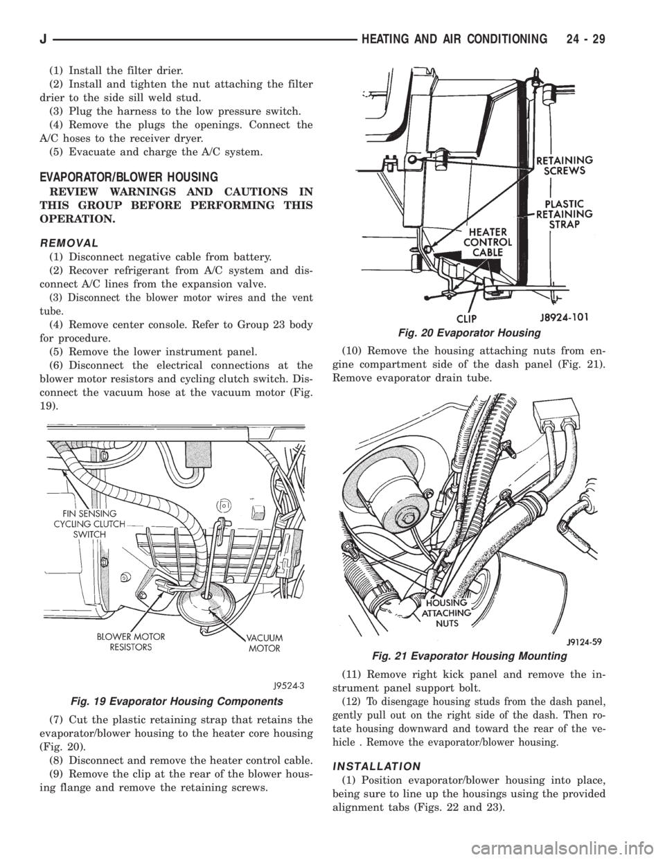
connect the vacuum hose at the vacuum motor (Fig.
19).
(7) Cut the plastic retaining strap that retains the
evaporator/blower housing to the heater core housing
(Fig. 20).
(8) Disconnect and remove the heater control cable.
(9) Remove the clip at the rear of the blower hous-
ing flange and remove the retaining screws.(10) Remove the housing attaching nuts from en-
gine compartment side of the dash panel (Fig. 21).
Remove evaporator drain tube.
(11) Remove right kick panel and remove the in-
strument panel support bolt.
(12) To disengage housing studs from the dash panel,
gently pull out on the right side of the dash. Then ro-
tate housing downward and toward the rear of the ve-
hicle . Remove the evaporator/blower housing.
INSTALLATION
(1) Position evaporator/blower housing into place,
being sure to line up the housings using the provided
alignment tabs (Figs. 22 and 23).
Fig. 19 Evaporator Housing Components
Fig. 20 Evaporator Housing
Fig. 21 Evaporator Housing Mounting
JHEATING AND AIR CONDITIONING 24 - 29
Page 2111 of 2158
(5) Remove expansion valve from the evaporator.
INSTALLATION
Add 30 ml (1 fluid oz.) of refrigerant oil to the A/C
system if the evaporator is replaced.
(1) Install expansion valve on evaporator.
(2) Position evaporator in the housing. Install and
tighten the evaporator retaining screws.
(3) Install cycling clutch switch into evaporator. In-
stall the top of the evaporator housing.
(4) Install the evaporator/blower housing.
(5) Evacuate and charge A/C system as outlined in
this section.
EXPANSION VALVE
REVIEW ALL WARNINGS AND CAUTIONS IN
THIS GROUP BEFORE PERFORMING THIS
OPERATION.
REMOVAL
(1) Recover refrigerant from A/C system.
(2) Remove the coolant bottle and bracket.
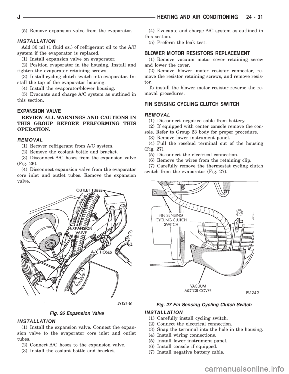
(3) Disconnect A/C hoses from the expansion valve
(Fig. 26).
(4) Disconnect expansion valve from the evaporator
core inlet and outlet tubes. Remove the expansion
valve.
INSTALLATION
(1) Install the expansion valve. Connect the expan-
sion valve to the evaporator core inlet and outlet
tubes.
(2) Connect A/C hoses to the expansion valve.
(3) Install the coolant bottle and bracket.(4) Evacuate and charge A/C system as outlined in
this section.
(5) Preform the leak test.
BLOWER MOTOR RESISTORS REPLACEMENT
(1) Remove vacuum motor cover retaining screw
and lower the cover.
(2) Remove blower motor resistor connector, re-
move the resistor retaining screws, and remove resis-
tor.
To install the blower motor resistor reverse the re-
moval procedures.
FIN SENSING CYCLING CLUTCH SWITCH
REMOVAL
(1) Disconnect negative cable from battery.
(2) If equipped with center console remove the con-
sole. Refer to Group 23 body for proper procedure.
(3) Remove lower instrument panel.
(4) Pull the rosebud terminal out of the housing
(Fig. 27).
(5) Disconnect the electrical connection.
(6) Remove the wires from the retaining clip.
(7) Carefully remove the thermostat cycling clutch
switch from the evaporator (Fig. 27).
INSTALLATION
(1) Carefully install cycling switch.
(2) Connect the electrical connection.
(3) Snap the terminal into the hole in the housing.
(4) Install wiring connections.
(5) Install lower instrument panel.
(6) Install console if equipped.
(7) Install negative battery cable.
Fig. 26 Expansion Valve
Fig. 27 Fin Sensing Cycling Clutch Switch
JHEATING AND AIR CONDITIONING 24 - 31
Page 2142 of 2158
MASTER CYLINDER, CLUTCH............0-22
MASTER CYLINDER INSTALLATION
(NON-ABS)..........................5-16
MASTER CYLINDER OVERHAUL
(4-CYLINDER MODELS)................5-16
MASTER CYLINDER REMOVAL
(NON-ABS)..........................5-15
MASTER CYLINDERÐCOMBINATION
VALVE ..............................5-15
MASTER CYLINDER/POWER BOOSTER
TEST................................5-8
MASTER CYLINDER/POWER BRAKE
BOOSTER............................5-34
MATCH MOUNTING....................22-7
MATERIAL, BRAKELINING................5-1
MATSÐXJ, CARPETS AND FLOOR.......23-99
MEASUREMENT AND ADJUSTMENT,
DIFFERENTIAL SHIM PACK..............2-43
MEASUREMENT AND ASSEMBLY, PINION . . 3-22
MEASUREMENT AND INSTALLATION,
DIFFERENTIAL........................3-25
MEASUREMENT AND TORQUE
SPECIFICATIONS...................Intro.-11
MEASUREMENT, DIFFERENTIAL AND
PINION.............................2-40
MEASUREMENT, UNIVERSAL JOINT
ANGLE..............................16-4
MEASUREMENTS AND ADJUSTMENTS,
ALIGNMENT...........................2-8
MEASURING WITH PLASTIGAGE..........9-3
MECHANISM, ARMING/DISARMING;
RESTRAINT SYSTEMS..................8M-2
MECHANISM, ARMING/DISARMING;
STEERING..........................19-48
MECHANISM, AUTOMATIC
TRANSMISSION SHIFTER/IGNITION
INTERLOCK.........................19-55
MECHANISM, SHIFT.................21-307
MEMORY, RADIO; RADIO (XJ)........8W-47-1
MEMORY, RADIO; RADIO (XJ-RHD)....8W-47-1
MEMORY, RADIO; RADIO (YJ)........8W-47-1
METAL DOOR MIRROR (EXTERNAL)Ð
YJ, HALF..........................23-121
METHODS AND PARTS USAGE,
INSTALLATION.........................6-4
METRIC AND ENGLISH/SAE
CONVERSION.....................Intro.-11
METRIC CONVERSION..............Intro.-16
METRIC, THREAD NOTATIONÐSAE....Intro.-13
(MFI)ÐCOMPONENT DESCRIPTION/
SYSTEM OPERATION, MULTI-PORT
FUEL INJECTION.....................14-19
(MFI)ÐCOMPONENT REMOVAL/
INSTALLATION, MULTI-PORT FUEL
INJECTION..........................14-58
(MFI)ÐGENERAL DIAGNOSIS,
MULTI-PORT FUEL INJECTION..........14-35
MINI-CONSOLE WITH FLOOR SHIFTÐXJ . . 23-94
MINI-FLOOR CONSOLEÐXJ............23-94
MIRROR (EXTERNAL)ÐYJ, HALF METAL
DOOR............................23-121
MIRROR LAMPS, VISOR VANITY;
INTERIOR LIGHTING (XJ)............8W-44-2
MIRROR LAMPS, VISOR VANITY;
INTERIOR LIGHTING (XJ-RHD)........8W-44-1
MIRROR, POWER.....................8T-1
MIRROR REMOVE/INSTALL, POWER
......8T-4
MIRROR RETAINING BRACKETÐYJ,
REARVIEW
.........................23-144
MIRROR SUPPORT BRACKET
REPLACEMENTÐXJ, INTERIOR
REARVIEW
..........................23-68
MIRROR SWITCH CONTINUITY (LEFT
POSITION), POWER
....................8T-3
MIRROR SWITCH CONTINUITY (RIGHT
POSITION), POWER
....................8T-3
MIRROR SWITCH, POWER
..........8T-1,8T-2
MIRROR SWITCH REMOVE/INSTALL,
POWER
.............................8T-4
MIRROR SYSTEM, POWER
..............8T-1
MIRROR TROUBLE DIAGNOSISÐXJ,
LIGHTED VANITY
.....................8L-16
MIRRORÐXJ, INTERIOR REARVIEW
.....23-66
MIRRORÐXJ, LIGHTED VANITY
.........8L-16
MIRRORÐYJ, REARVIEW
.............23-144
MIRRORS, POWER; POWER MIRRORS
(XJ)
.............................8W-62-1MIRRORS, POWER; POWER MIRRORS
(XJ-RHD).........................8W-62-1
MIRRORSÐXJ, EXTERNAL.............23-27
MISALIGNMENT, CLUTCH................6-3
MISALIGNMENT, CLUTCH HOUSING........6-4
MISS, INJECTOR DIAGNOSISÐVEHICLE
RUNS ROUGH AND/OR HAS A..........14-52
MODE, ABS OPERATION IN ANTILOCK
BRAKING............................5-36
MODE, ABS OPERATION IN NORMAL
BRAKING............................5-35
MODEL 30 AXLE......................2-49
MODEL 30 AXLE AND TUBE AXLE (2WD) . . 2-22
MODEL 30 FRONT AXLE................2-49
MODEL 35 AXLE..................3-13,3-51
MODELS, BELT TENSIONÐEXCEPT
RIGHT HAND DRIVE (RHD)..............7-45
MODELS, IGNITION SWITCHÐXJ........8D-26
MODELS, IGNITION SWITCHÐYJ........8D-29
MODELS WITH 4.0L 6-CYLINDER
ENGINE, AUXILIARY ELECTRIC
COOLING FANÐXJ....................7-35
MODELS WITH RIGHT HAND DRIVE,
AUTOMATIC BELT TENSIONERÐXJ.......7-42
MODELS WITH RIGHT HAND DRIVE,
BELT SERVICEÐXJ....................7-42
MODES OF OPERATION, OPEN
LOOP/CLOSED LOOP..................14-30
MODULE, AIRBAG....................8M-1
MODULE, BUZZER................8U-1,8U-2
MODULE, CHIME/BUZZER; INTERIOR
LIGHTING (XJ)....................8W-44-2
MODULE, CHIME/BUZZER; INTERIOR
LIGHTING (XJ-RHD)................8W-44-2
MODULE, DAYTIME RUNNING LAMP
(DRL); FRONT LIGHTING (XJ)........8W-50-2
MODULE, DIMMING; FRONT LIGHTING
(XJ-RHD).........................8W-50-1
MODULE, FUEL PUMP; FUEL SYSTEM....14-61,
14-3
MODULE, FUEL PUMP; FUEL/IGNITION
(XJ).............................8W-30-2
MODULE, FUEL PUMP; FUEL/IGNITION
(YJ).............................8W-30-2
MODULE, FUEL PUMP; FUEL/IGNITION
(XJ-RHD).........................8W-30-2
MODULE HANDLING, AIRBAG...........8M-2
MODULE, HEADLAMP DELAY; FRONT
LIGHTING (XJ)....................8W-50-2
MODULE, HEADLAMP DELAY; FRONT
LIGHTING (XJ-RHD)................8W-50-1
MODULE, INTERMITTENT WIPE..........8K-4
MODULE, KEYLESS ENTRY.........8P-1,8P-7
MODULE (PCM) 60-WAY CONNECTOR,
POWERTRAIN CONTROL...............14-40
MODULE (PCM), POWERTRAIN
CONTROL; EMISSION CONTROL
SYSTEMS...........................25-7
MODULE (PCM), POWERTRAIN
CONTROL; FUEL SYSTEM.........14-20,14-64
MODULE (PCM), POWERTRAIN
CONTROL; IGNITION SYSTEMS....8D-11,8D-23,
8D-5
MODULE, POWERTRAIN CONTROL . . . 8H-1,8H-7
MODULE, REMOTE KEYLESS ENTRY . . . 8W-61-1
MODULE REMOVE/INSTALL, AIRBAG.....8M-3
MODULE REMOVE/INSTALL, KEYLESS
ENTRY.............................8P-10
MODULE REMOVEÐINSTALL, AIRBAG....19-49
MODULE REPLACEMENTÐXJ, DRL......8L-15
MODULE REPLACEMENTÐXJ,
HEADLAMP DELAY...................8L-14
MODULE REPLACEMENTÐYJ, DRL......8L-30
MODULE SCHEMATIC - YJ, BUZZER......8U-4
MODULE (TCM) SERVICE,
TRANSMISSION CONTROL............21-183
MODULE, TRANSMISSION CONTROL;
TRANSMISSION CONTROLS (XJ-RHD) . . 8W-31-1
MODULEÐ4.0L ENGINE ONLY,
TRANSMISSION CONTROL;
TRANSMISSION CONTROLS (XJ)......8W-31-1
MODULEÐCANADIAN VEHICLES ONLY,
DAYTIME RUNNING LAMP (DRL)
......8W-50-2
MODULEÐXJ, SENTINEL HEADLAMP
DELAY
.............................8L-14
MOLDING/CLADDINGÐXJ, BODY SIDE
. . . 23-20
MOLDINGÐXJ, DRIP RAIL
.............23-25
MOLDINGÐXJ, WINDSHIELD REVEAL
....23-66MOLDINGÐXJ, WINDSHIELD SIDE......23-86
MOLDINGÐYJ, BODY SIDE STEP.......23-115
MOLDINGÐYJ, WINDSHIELD REVEAL . . . 23-144
MOLDINGSÐXJ, DOOR WINDOW
EXTERIOR..........................23-54
MOTOR, A/C BLOWER.................24-35
MOTOR, A/C-HEATER BLOWER; AIR
CONDITIONING/HEATER (YJ).........8W-42-2
MOTOR, BLOWER; AIR CONDITIONING/
HEATER (XJ)......................8W-42-1
MOTOR, BLOWER; AIR CONDITIONING/
HEATER (XJ-RHD)..................8W-42-1
MOTOR, BLOWER; HEATING AND AIR
CONDITIONING......................24-17
MOTOR DIAGNOSIS (CONT'D),
DISCONNECT AXLE/SHIFT...............2-30
MOTOR DIAGNOSIS, DISCONNECT
AXLE/SHIFT..........................2-29
MOTOR, FRESH AIR DOOR VACUUM.....24-34
MOTOR (HEATING), BLOWER...........24-33
MOTOR, IDLE AIR CONTROL (IAC); FUEL
SYSTEM............................14-62
MOTOR, IDLE AIR CONTROL (IAC);
FUEL/IGNITION (XJ)................8W-30-2
MOTOR, IDLE AIR CONTROL (IAC);
FUEL/IGNITION (YJ)................8W-30-2
MOTOR, IDLE AIR CONTROL (IAC);
FUEL/IGNITION (XJ-RHD)............8W-30-2
MOTOR, POWER LOCK.............8P-1,8P-7
MOTOR, POWER WINDOW..........8S-1,8S-2
MOTOR, RADIATOR FAN RELAY; AIR
CONDITIONING/HEATER (XJ).........8W-42-2
MOTOR, RADIATOR FAN RELAY; AIR
CONDITIONING/HEATER (XJ-RHD).....8W-42-2
MOTOR RELAY, ABS PUMP; ANTI-LOCK
BRAKES (XJ)......................8W-32-1
MOTOR RELAY, ABS PUMP; ANTI-LOCK
BRAKES (XJ-RHD).................8W-32-1
MOTOR RELAY, ABS PUMP; ANTI-LOCK
BRAKES (YJ)......................8W-32-1
MOTOR RELAY TEST, STARTER.........14-51
MOTOR REMOVE/INSTALL, LIFTGATE
WIPER.........................8K-20,8K-6
MOTOR REMOVE/INSTALL, POWER
LOCK...............................8P-8
MOTOR REMOVE/INSTALL, POWER
WINDOW............................8S-7
MOTOR REMOVE/INSTALL, WINDSHIELD
WIPER.........................8K-19,8K-6
MOTOR REPLACEMENT, A/C
RECIRCULATING DOOR VACUUM........24-27
MOTOR REPLACEMENT, HEATER/
DEFROSTER/INSTRUMENT PANEL
OUTLET VACUUM....................24-26
MOTOR RESISTORS REPLACEMENT,
BLOWER...........................24-31
MOTOR SPEED SENSOR, PUMP;
ANTI-LOCK BRAKES (XJ)............8W-32-2
MOTOR SPEED SENSOR, PUMP;
ANTI-LOCK BRAKES (XJ-RHD)........8W-32-2
MOTOR SPEED SENSOR, PUMP;
ANTI-LOCK BRAKES (YJ)............8W-32-1
MOTOR SWITCH, BLOWER.............24-16
MOTOR SWITCH REPLACEMENT,
BLOWER MOTOR/AIR DOOR............24-32
MOTOR TEST, IDLE AIR CONTROL.......14-49
MOTOR/AIR DOOR MOTOR SWITCH
REPLACEMENT, BLOWER
..............24-32
MOTOR/FAN REPLACEMENT, BLOWER
....24-24
MOTORÐPCM OUTPUT, IDLE AIR
CONTROL (IAC)
......................14-27
MOUNTED STOP LAMP (CHMSL)ÐXJ,
CENTER HIGH
.......................8L-12
MOUNTED STOP LAMP (CHMSL)ÐYJ,
CENTER HIGH
.......................8L-28
MOUNTING, MATCH
...................22-7
MOUNTÐREAR, ENGINE
...........9-16,9-57
MOUNTSÐFRONT, ENGINE
..........9-14,9-56
MUFFLER AND EXHAUST TAILPIPEÐXJ
VEHICLES
...........................11-5
MUFFLER AND EXHAUST TAILPIPEÐYJ
VEHICLES
...........................11-6
MULTI-FUNCTION SWITCH - XJ
..........8J-4
MULTI-FUNCTION SWITCH REMOVE/
INSTALL - XJ
.........................8J-5
MULTI-FUNCTION SWITCH SERVICE
PROCEDURESÐXJ
...................8L-11
18 INDEXJ
Description Group-Page Description Group-Page Description Group-Page