1995 JEEP YJ climate control
[x] Cancel search: climate controlPage 23 of 2158

MAINTENANCE SCHEDULES
INTRODUCTION
There are two maintenance schedules that show
proper service intervals for Jeep Cherokee and Jeep
Wrangler vehicles. Use the schedule that best de-
scribes the conditions the vehicle is operated under.
When mileage and time is listed, follow the interval
that occurs first.
ScheduleÐAlists all the scheduled maintenance
to be performed under normal operating conditions.
ScheduleÐBis a schedule for vehicles that are
usually operated under one or more of the following
conditions.
²Frequent short trip driving less than 5 miles (8
km).
²Frequent driving in dusty conditions.
²Trailer towing or heavy load hauling.
²Frequent long periods of engine idling.
²Sustained high speed operation.
²Desert operation.
²Frequent starting and stopping.
²Cold climate operation.
²Off road driving.
²Commercial service.
²Snow plow operation.
²More than half of vehicle operation occurs in
heavy city traffic during hot weather (above 90É F).
AT EACH STOP FOR GASOLINE
²Check engine oil level and add as required.
²Check windshield washer solvent and add as re-
quired.
ONCE A MONTH
²Check tire pressure and look for unusual tire wear
or damage.
²Check fluid levels of coolant reservoir, brake mas-
ter cylinder, power steering and transmission. Add
fluid as required.
²Check all lights and other electrical items for cor-
rect operation.
²Inspect battery and clean and tighten terminals as
required.
²Check rubber seals on each side of the radiator for
proper fit.
AT EACH OIL CHANGE
²Inspect exhaust system.
²Inspect brake hoses.
²Rotate the tires at each oil change interval shown
on ScheduleÐA: (7,500 Miles) or every other interval
shown on ScheduleÐB: (6,000 Miles).
²Check engine coolant level, hoses, and clamps.
²Lubricate 4x4 steering linkage.
²Lubricate propeller shaft universal joints and slip
spline, if equipped.After completion of off-road (4WD) operation, the
underside of the vehicle should be thoroughly in-
spected. Examine threaded fasteners for looseness.
HARSH SURFACE ENVIRONMENTS
After vehicle operation in a harsh surface environ-
ment, the following components should be inspected
and cleaned as soon as possible:
²Brake drums.
²Brake linings.
²Front wheel bearings (2WD vehicles only).
²Axle coupling joints.
This will prevent wear and/or unpredictable brake
action.
EMISSION CONTROL SYSTEM MAINTENANCE
The schedule emission maintenance listed inbold
typeon the following schedules, must be done at the
mileage specified to assure the continued proper
functioning of the emission control system. These,
and all other maintenance services included in this
manual, should be done to provide the best vehicle
performance and reliability. More frequent mainte-
nance may be needed for vehicles in severe operating
conditions such as dusty areas and very short trip
driving.
SCHEDULEÐA
7,500 MILES (12 000 KM) OR AT 6 MONTHS
²Change engine oil.
²Replace engine oil filter.
²Lubricate steering linkage (4x4).
15,000 MILES (24 000 KM) OR AT 12 MONTHS
²Change engine oil.
²Replace engine oil filter.
²Lubricate steering linkage.
22,500 MILES (36 000 KM) OR AT 18 MONTHS
²Change engine oil.
²Replace engine oil filter.
²Lubricate steering linkage (4x4).
²Inspect brake linings.
30,000 MILES (48 000 KM) OR AT 24 MONTHS
²Replace air cleaner element.
²Replace spark plugs.
²Adjust belt tension on non-automatic tensioning
drive belts.
²Change engine oil.
²Replace engine oil filter.
²Lubricate steering linkage.
²Drain and refill automatic transmission.
²Drain and refill transfer case.
0 - 4 LUBRICATION AND MAINTENANCEJ
Page 376 of 2158

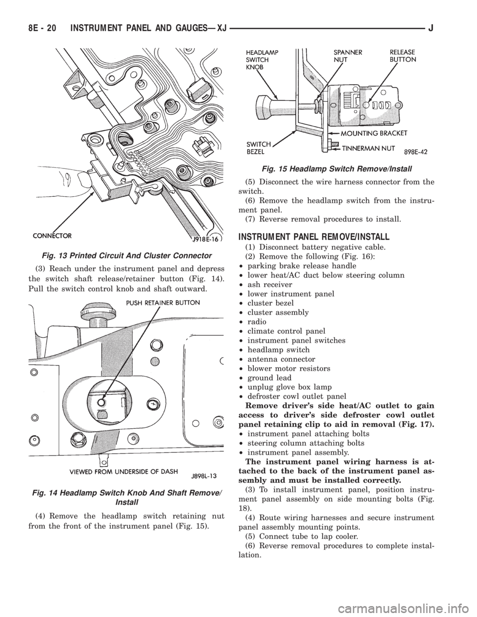
(3) Reach under the instrument panel and depress
the switch shaft release/retainer button (Fig. 14).
Pull the switch control knob and shaft outward.
(4) Remove the headlamp switch retaining nut
from the front of the instrument panel (Fig. 15).(5) Disconnect the wire harness connector from the
switch.
(6) Remove the headlamp switch from the instru-
ment panel.
(7) Reverse removal procedures to install.
INSTRUMENT PANEL REMOVE/INSTALL
(1) Disconnect battery negative cable.
(2) Remove the following (Fig. 16):
²parking brake release handle
²lower heat/AC duct below steering column
²ash receiver
²lower instrument panel
²cluster bezel
²cluster assembly
²radio
²climate control panel
²instrument panel switches
²headlamp switch
²antenna connector
²blower motor resistors
²ground lead
²unplug glove box lamp
²defroster cowl outlet panel
Remove driver's side heat/AC outlet to gain
access to driver's side defroster cowl outlet
panel retaining clip to aid in removal (Fig. 17).
²instrument panel attaching bolts
²steering column attaching bolts
²instrument panel assembly.
The instrument panel wiring harness is at-
tached to the back of the instrument panel as-
sembly and must be installed correctly.
(3) To install instrument panel, position instru-
ment panel assembly on side mounting bolts (Fig.
18).
(4) Route wiring harnesses and secure instrument
panel assembly mounting points.
(5) Connect tube to lap cooler.
(6) Reverse removal procedures to complete instal-
lation.
Fig. 13 Printed Circuit And Cluster Connector
Fig. 14 Headlamp Switch Knob And Shaft Remove/
Install
Fig. 15 Headlamp Switch Remove/Install
8E - 20 INSTRUMENT PANEL AND GAUGESÐXJJ
Page 2103 of 2158

COMPONENT SERVICEÐXJ VEHICLES
INDEX
page page
A/C Recirculating Door Vacuum Motor
Replacement........................... 27
Blower Motor Resistors Replacement.......... 31
Blower Motor/Fan Replacement............... 24
Condenser Filter DrierÐ2.5L Engines.......... 27
CondenserÐ4.0L Engines................... 28
Description.............................. 23
Evaporator Coil........................... 30
Evaporator/Blower Housing.................. 29Expansion Valve.......................... 31
Filter DrierÐ4.0L Engines................... 28
Fin Sensing Cycling Clutch Switch............. 31
Heater and A/C Control Replacement.......... 23
Heater Core............................. 26
Heater Housing Replacement................ 26
Heater/Defroster/Instrument Panel Outlet Vacuum
Motor Replacement...................... 26
DESCRIPTION
The Climate Control System combines air condi-
tioning, heating and ventilating capabilities for vehi-
cles equipped with air conditioning. Vehicles without
air conditioning perform heating and ventilating
functions without the air conditioning evaporator.
Both systems consist basically of 2 parts:
²Blower and Air Inlet Assembly
²Heater Core and Air Distribution Assembly
These unit may be removed separately from under
the instrument panel for service.
HEATER AND A/C CONTROL REPLACEMENT
(1) Disconnect negative cable from battery.
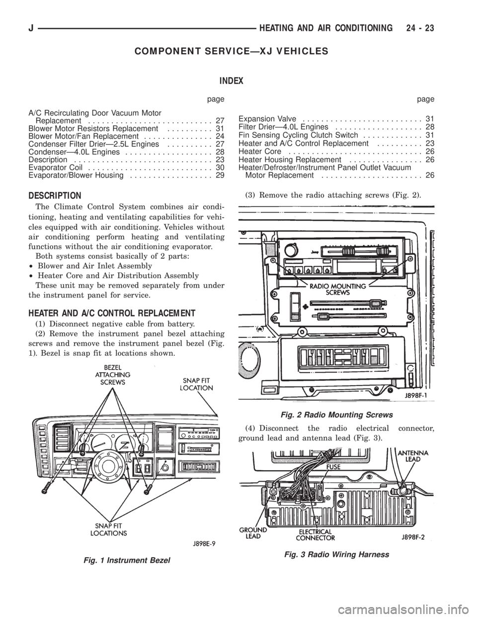
(2) Remove the instrument panel bezel attaching
screws and remove the instrument panel bezel (Fig.
1). Bezel is snap fit at locations shown.(3) Remove the radio attaching screws (Fig. 2).
(4) Disconnect the radio electrical connector,
ground lead and antenna lead (Fig. 3).
Fig. 1 Instrument Bezel
Fig. 2 Radio Mounting Screws
Fig. 3 Radio Wiring Harness
JHEATING AND AIR CONDITIONING 24 - 23