1995 JEEP YJ battery replacement
[x] Cancel search: battery replacementPage 34 of 2158

ENGINE MAINTENANCE
INDEX
page page
Accessory Drive Belt....................... 21
Air Cleaner Element....................... 18
Air-Conditioner Compressor.................. 21
Battery................................. 20
Crankcase Ventilation System................ 19
Emission Control System................... 20
Engine Break-In.......................... 15
Engine Cooling System..................... 18
Engine Oil.............................. 15Engine Oil Change and Filter Replacement...... 16
Engine Oil Filter.......................... 17
Engine Supports.......................... 21
Exhaust System.......................... 21
Fuel Filter............................... 19
Fuel Usage StatementÐGas Engines.......... 19
Ignition Cables, Distributor Cap and Rotor....... 20
Rubber and Plastic Component Inspection....... 20
Spark Plugs............................. 20
ENGINE BREAK-IN
CAUTION: Wide open throttle operation in low
gears, before engine break-in period is complete,
can damage engine.
After first starting a new engine, allow it to idle for
15 seconds before shifting into a drive gear. Also:
²Drive the vehicle at varying speeds less than 88
km/h (55 mph) for the first 480 km (300 miles).
²Avoid fast acceleration and sudden stops.
²Do not drive at full-throttle for extended periods of
time.
²Do not drive at constant speeds.
²Do not idle the engine excessively.
A special break-in engine oil is not required. The
original engine oil installed is a high quality, energy
conserving lubricant. Special break-in oils are not
recommended. These oils could interfere with the
normal piston ring seating process.
New engines tend to consume more fuel and oil un-
til after the break-in period has ended.
ENGINE OIL
WARNING: NEW OR USED ENGINE OIL CAN BE IR-
RITATING TO THE SKIN. AVOID PROLONGED OR
REPEATED SKIN CONTACT WITH ENGINE OIL.
CONTAMINANTS IN USED ENGINE OIL, CAUSED BY
INTERNAL COMBUSTION, CAN BE HAZARDOUS TO
YOUR HEALTH. THOROUGHLY WASH EXPOSED
SKIN WITH SOAP AND WATER.
DO NOT WASH SKIN WITH GASOLINE, DIESEL
FUEL, THINNER, OR SOLVENTS, HEALTH PROB-
LEMS CAN RESULT.
DO NOT POLLUTE, DISPOSE OF USED ENGINE
OIL PROPERLY. CONTACT YOUR DEALER OR GOV-
ERNMENT AGENCY FOR LOCATION OF COLLEC-
TION CENTER IN YOUR AREA.
ENGINE OIL SPECIFICATION
CAUTION: Do not use non-detergent or straight
mineral oil when adding or changing crankcase lu-
bricant. Engine failure can result.
API SERVICE GRADE CERTIFIED
Use an engine oil that is API Service Grade Certi-
fied or an oil that conforms to the API Service Grade
SH or SH/CD. MOPAR provides engine oils that con-
form to all of these service grades.
SAE VISCOSITY
An SAE viscosity grade is used to specify the vis-
cosity grade of engine oil. SAE 30 specifies a single
viscosity engine oil. Engine oils also have multiple
viscosities. These are specified with a dual SAE vis-
cosity grade which indicates the cold-to-hot tempera-
ture viscosity range. Select an engine oil that is best
suited to your particular temperature range and vari-
ation (Fig.1).
ENERGY CONSERVING OIL
An Energy Conserving type oil is recommeded for
gasoline engines. They are designated as either EN-
ERGY CONSERVING or ENERGY CONSERVING
II.
Fig. 1 Temperature/Engine Oil Viscosity
JLUBRICATION AND MAINTENANCE 0 - 15
Page 39 of 2158

line. You may encounter fuels containing 3 percent or
more methanol along with other alcohols called cosol-
vents.
Problems that are the result of using methanol/gas-
oline blends are not the responsibility of Chrysler
Corporation. They may not be covered by the vehicle
warranty.
MTBE/ETBE
Gasoline and MTBE (Methyl Tertiary Butyl Ether)
blends are a mixture of unleaded gasoline and up to
15 percent MTBE. Gasoline and ETBE (Ethyl Ter-
tiary Butyl Ether) are blends of gasoline and up to
17 percent ETBE. Gasoline blended with MTBE or
ETBE may be used.
CLEAN AIR GASOLINE
Many gasolines are now being blended that con-
tribute to cleaner air, especially in those areas of the
country where air pollution levels are high. These
new blends provide a cleaner burning fuel and some
are referred to asReformulated Gasoline.
In areas of the country where carbon monoxide lev-
els are high, gasolines are being treated with oxygen-
ated materials such as MTBE, ETBE and ethanol.
Chrysler Corporation supports these efforts toward
cleaner air and recommends the use of these gaso-
lines as they become available.
IGNITION CABLES, DISTRIBUTOR CAP AND
ROTOR
Inspect and test ignition cables, distributor cap and
rotor when the spark plugs are replaced. Oil and
grime should be cleaned from the ignition cables and
distributor cap to avoid possible spark plug fouling.
Mopar Foamy Engine Degreaser or equivalent is rec-
ommended for cleaning the engine compartment. For
proper service and diagnostic procedures refer to
Group 8D, Ignition System.
IGNITION TIMING
The ignition timing for 2.5L and 4.0L engines is
not adjustable. Refer to the specifications listed on
the engine Emission Control Information Label. Re-
fer to Group 25, Emission Control Systems for addi-
tional information.
SPARK PLUGS
Ignition spark plugs should be replaced at the
mileage interval described in the Lubrication and
Maintenance Schedules. Refer to the General Infor-
mation section of this group. For proper service pro-
cedures refer to Group 8D, Ignition Systems.
BATTERY
WARNING: WEAR SAFETY GLASSES, RUBBER
GLOVES AND PROTECTIVE CLOTHING WHEN HAN-DLING/SERVICING A BATTERY. THE BATTERY
ELECTROLYTE CONTAINS SULFURIC ACID AND
WILL CAUSE HARM IF IT CONTACTS SKIN, EYES
OR CLOTHING. IT WILL ALSO DAMAGE PAINTED
(AS WELL AS UN-PAINTED) SURFACES OF A VEHI-
CLE. IF SULFURIC ACID CONTACTS ANY OF
THESE, FLUSH IMMEDIATELY WITH LARGE
AMOUNTS OF WATER. IF SULFURIC ACID CON-
TACTS SKIN OR EYES, GET IMMEDIATE MEDICAL
ATTENTION. DO NOT SMOKE IN THE VICINITY OF A
BATTERY. KEEP OPEN FLAMES AND SPARKS
AWAY FROM BATTERY FILLER CAPS BECAUSE
EXPLOSIVE GAS IS ALWAYS PRESENT.
Inspect battery tray, hold down and terminal con-
nections when other under hood service is performed.
For proper diagnostic procedures refer to Group 8A,
Battery/Starting/Charging System Diagnostics. For
service and cleaning procedures refer to Group 8B,
Battery/Starter Service.
Care should be taken when disposing a bat-
tery after removal from a vehicle. Lead-acid
batteries are highly poisonous and, when indis-
criminately disposed, could create a problem
for the environment. Contact the applicable lo-
cal city or county government agency to deter-
mine where automobile (lead-acid) batteries
can be properly disposed in the local area.
RUBBER AND PLASTIC COMPONENT INSPECTION
CAUTION: Plastic hoses or wire harness covers will
melt or deform when exposed to heat from exhaust
system or engine manifolds.
Position plastic or rubber components away from
moving parts in engine compartment or under vehi-
cle, or damage will result.
Do not allow rubber engine mounts or other com-
ponents to become oil contaminated, repair cause
of oil contamination and clean area.
All rubber and plastic components should be in-
spected when engine compartment or under vehicle
service is performed. When evidence of deterioration
exists, replacement is required. To reduce deteriora-
tion of rubber components, Chrysler Corporation rec-
ommends Mopar Foamy Engine Degreaser or
equivalent be used to clean engine compartment of
oil and road grime.
EMISSION CONTROL SYSTEM
Inspect all emission control components and hoses
when other under hood service is performed. Refer to
emission system Vacuum Hose Label located on the
inside of the hood in the engine compartment and
Group 25, Emission Control Systems for proper ser-
vice procedures.
0 - 20 LUBRICATION AND MAINTENANCEJ
Page 311 of 2158

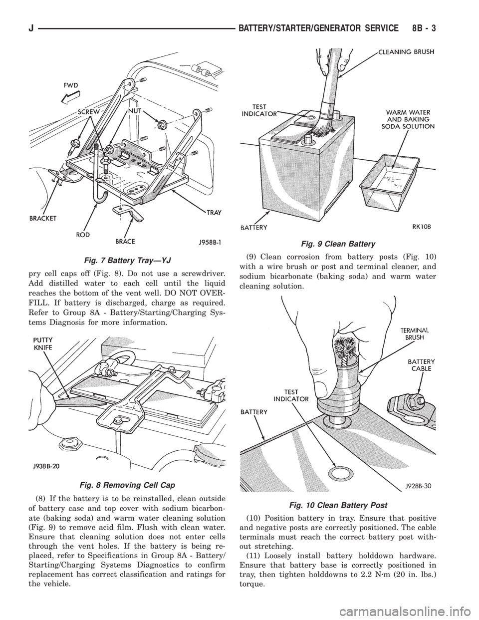
pry cell caps off (Fig. 8). Do not use a screwdriver.
Add distilled water to each cell until the liquid
reaches the bottom of the vent well. DO NOT OVER-
FILL. If battery is discharged, charge as required.
Refer to Group 8A - Battery/Starting/Charging Sys-
tems Diagnosis for more information.
(8) If the battery is to be reinstalled, clean outside
of battery case and top cover with sodium bicarbon-
ate (baking soda) and warm water cleaning solution
(Fig. 9) to remove acid film. Flush with clean water.
Ensure that cleaning solution does not enter cells
through the vent holes. If the battery is being re-
placed, refer to Specifications in Group 8A - Battery/
Starting/Charging Systems Diagnostics to confirm
replacement has correct classification and ratings for
the vehicle.(9) Clean corrosion from battery posts (Fig. 10)
with a wire brush or post and terminal cleaner, and
sodium bicarbonate (baking soda) and warm water
cleaning solution.
(10) Position battery in tray. Ensure that positive
and negative posts are correctly positioned. The cable
terminals must reach the correct battery post with-
out stretching.
(11) Loosely install battery holddown hardware.
Ensure that battery base is correctly positioned in
tray, then tighten holddowns to 2.2 Nzm (20 in. lbs.)
torque.
Fig. 7 Battery TrayÐYJ
Fig. 8 Removing Cell Cap
Fig. 9 Clean Battery
Fig. 10 Clean Battery Post
JBATTERY/STARTER/GENERATOR SERVICE 8B - 3
Page 314 of 2158

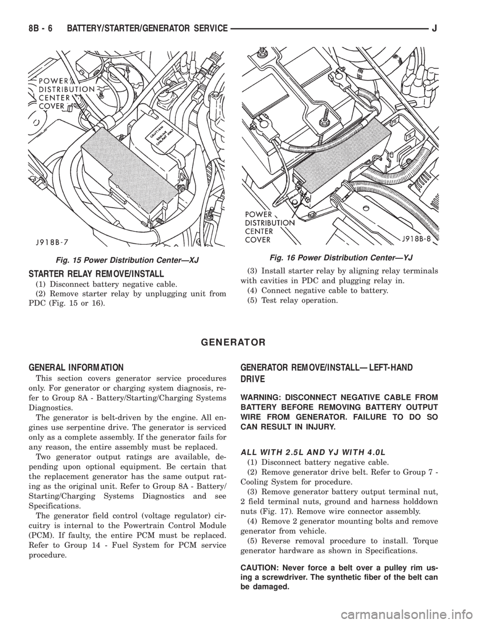
STARTER RELAY REMOVE/INSTALL
(1) Disconnect battery negative cable.
(2) Remove starter relay by unplugging unit from
PDC (Fig. 15 or 16).(3) Install starter relay by aligning relay terminals
with cavities in PDC and plugging relay in.
(4) Connect negative cable to battery.
(5) Test relay operation.
GENERATOR
GENERAL INFORMATION
This section covers generator service procedures
only. For generator or charging system diagnosis, re-
fer to Group 8A - Battery/Starting/Charging Systems
Diagnostics.
The generator is belt-driven by the engine. All en-
gines use serpentine drive. The generator is serviced
only as a complete assembly. If the generator fails for
any reason, the entire assembly must be replaced.
Two generator output ratings are available, de-
pending upon optional equipment. Be certain that
the replacement generator has the same output rat-
ing as the original unit. Refer to Group 8A - Battery/
Starting/Charging Systems Diagnostics and see
Specifications.
The generator field control (voltage regulator) cir-
cuitry is internal to the Powertrain Control Module
(PCM). If faulty, the entire PCM must be replaced.
Refer to Group 14 - Fuel System for PCM service
procedure.
GENERATOR REMOVE/INSTALLÐLEFT-HAND
DRIVE
WARNING: DISCONNECT NEGATIVE CABLE FROM
BATTERY BEFORE REMOVING BATTERY OUTPUT
WIRE FROM GENERATOR. FAILURE TO DO SO
CAN RESULT IN INJURY.
ALL WITH 2.5L AND YJ WITH 4.0L
(1) Disconnect battery negative cable.
(2) Remove generator drive belt. Refer to Group 7 -
Cooling System for procedure.
(3) Remove generator battery output terminal nut,
2 field terminal nuts, ground and harness holddown
nuts (Fig. 17). Remove wire connector assembly.
(4) Remove 2 generator mounting bolts and remove
generator from vehicle.
(5) Reverse removal procedure to install. Torque
generator hardware as shown in Specifications.
CAUTION: Never force a belt over a pulley rim us-
ing a screwdriver. The synthetic fiber of the belt can
be damaged.
Fig. 15 Power Distribution CenterÐXJFig. 16 Power Distribution CenterÐYJ
8B - 6 BATTERY/STARTER/GENERATOR SERVICEJ
Page 402 of 2158

ANTENNA
All models use a fixed-length stainless steel rod-
type antenna mast, installed at the right front (fend-
er on XJ, cowl side on YJ) of the vehicle. The
antenna mast is connected to the center wire of the
coaxial antenna cable and is not grounded to any
part of the vehicle.
To eliminate static, the antenna base must have a
good ground. The coaxial antenna cable shield (the
outer wire mesh of the cable) is grounded to the an-
tenna base and the radio chassis.
The factory installed ETRs automatically compen-
sate for radio antenna trim. Therefore, no antenna
trimmer adjustment is required or possible when re-
placing the receiver or the antenna.
RADIO NOISE SUPPRESSION
Radio Frequency Interference (RFI) and Electro-
Magnetic Interference (EMI) noise suppression is ac-
complished primarily through circuitry internal to
the radio receivers. These internal suppression de-
vices are only serviced as a part of the radio receiver.External suppression devices that are serviceable
and should be checked in the case of RFI or EMI
noise complaints include the following:
²radio antenna base ground
²engine-to-body ground strap
²resistor-type spark plugs
²radio suppression-type secondary ignition wiring.
In addition, if the source of RFI or EMI noise is
identified as a component on the vehicle (i.e.:genera-
tor, blower motor, etc.), the ground path for that com-
ponent should be checked. If excessive resistance is
found in that circuit, repair as required before con-
sidering any component replacement.
Fleet vehicles are available with an extra-cost RFI-
suppressed Powertrain Control Module (PCM). This
unit reduces interference generated by the PCM on
some radio frequencies used in two-way radio com-
munications. However, this unit will not resolve com-
plaints of RFI in the commercial AM or FM radio
frequency ranges.
DIAGNOSIS
RADIO
CAUTION: Do not operate the radio with speaker
leads detached since damage to the transistors
may result.
(1) Check fuse 2 in fuseblock module and fuse in
back of radio chassis. If OK, go to next step. If not
OK, replace fuse.
(2) Turn ignition switch to ON position. Check for
battery voltage at fuse 2. If OK, go to next step. If
not OK, repair circuit to ignition switch as required.
(3) Turn ignition switch to OFF position. Discon-
nect battery negative cable. Remove instrument clus-
ter bezel. Remove radio, but do not unplug any
connections. Check for continuity between the radio
chassis and a good ground. There should be continu-
ity. If OK, go to next step. If not OK, repair radio
ground circuit as required.
(4) Connect battery negative cable. Turn ignition
switch to ON position. See Radio Connections chart.
Check for battery voltage at cavity 3 of radio connec-
tor. If OK, go to next step. If not OK, repair circuit to
fuse 2 as required.
(5) Turn ignition switch to OFF position. Check for
battery voltage at cavity 4 of radio connector. If OK,
replace radio. If not OK, repair circuit to IOD fuse in
PDC as required.
SPEAKERS
CAUTION: Do not operate the radio with speaker
leads detached since damage to the transistors
may result.
(1) Turn radio on and adjust balance and fader
controls to check performance of each individual
speaker. Note the speaker locations that are not per-
forming correctly. Go to next step.
(2) Turn radio off. Disconnect battery negative ca-
ble. Remove instrument cluster bezel and remove ra-
dio. See Radio Connections chart. Check both the
speaker feed and return cavities at radio for continu-
ity to a good ground. There should be no continuity.
If OK, go to next step. If not OK, repair wiring cir-
cuit as required.
(3) Check resistance between speaker feed and re-
turn cavities. Meter should read between 3 and 8
ohms (speaker impedance). If OK, see diagnosis for
Radio. If not OK, go to next step.
(4) Unplug speaker wiring connector. Check for
continuity between speaker feed cavity at radio and
at speaker. Repeat check between speaker return
cavity at radio and at speaker. If OK, replace
speaker. If not OK, repair wiring circuit as required.
8F - 2 AUDIO SYSTEMSJ
Page 474 of 2158

INSTALLATION
(1) Position the underhood lamp on the hood inner
panel.
(2) Install the attaching screw through the lamp
and into the hood panel. Tighten the screw securely.
(3) Insert a replacement bulb in the lamp base
socket and rotate it clockwise.
(4) Connect the wire harness connector to the
lamp.
SENTINEL HEADLAMP DELAY MODULEÐXJ
SERVICE INFORMATION
The Headlamp Module delays the de-activation of
the headlamps for 45615 seconds after the ignition
switch is turned OFF. The driver engages the module
by turning the ignition switch OFF, then turning the
headlamps OFF.
The headlamp delay module is located behind the
I/P next to the headlamp switch.
HEADLAMP DELAY MODULE REPLACEMENTÐXJ
The headlamp delay module is attached to the in-
side of the instrument panel to the right of the head-
lamp switch.
REMOVAL
(1) Remove the lower instrument panel.(2) Remove the screw that attaches the module to
the inside of the instrument panel.
(3) Disconnect the wire harness connector and re-
move the module from the instrument panel.
INSTALLATION
(1) Position the module inside the I/P and connect
the wire harness connector to the module.
(2) Install the screw that attaches the module to
the inside of the instrument panel.
(3) Remove the lower instrument panel.
HEADLAMP DELAY FUNCTION TROUBLE
DIAGNOSISÐXJ
DELAY FUNCTION INOPERATIVE
(1) Remove, inspect and test the HD LP DLY fuse.
Replace if defective.
(2) Remove the delay module from the I/P. Do not
disconnect the wire harness connector. Turn the igni-
tion switch to the RUN position. Place the headlamp
switch in headlamps ON position. Turn the ignition
to the OFF position for a resistance test.
(3) Measure the resistance from the delay module
terminal 4 to vehicle body ground. The ohmmeter
should indicate zero ohms. If not, repair the open cir-
cuit in the wire harness to vehicle body ground.
(4) Measure the voltage between the delay module
terminal 8 and vehicle body ground. The voltmeter
should indicate battery voltage. If not, repair the
open circuit in the wire harness to the instrument
cluster indicator connector terminal 14.
(5) Measure the voltage between the delay module
terminal 6 and vehicle body ground. The voltmeter
should indicate battery voltage. If not, repair the
open circuit in the wire harness to the headlamp
switch.
(6) Measure the voltage between the delay module
terminal 2 and vehicle body ground. The voltmeter
should indicate battery voltage. If not, repair the
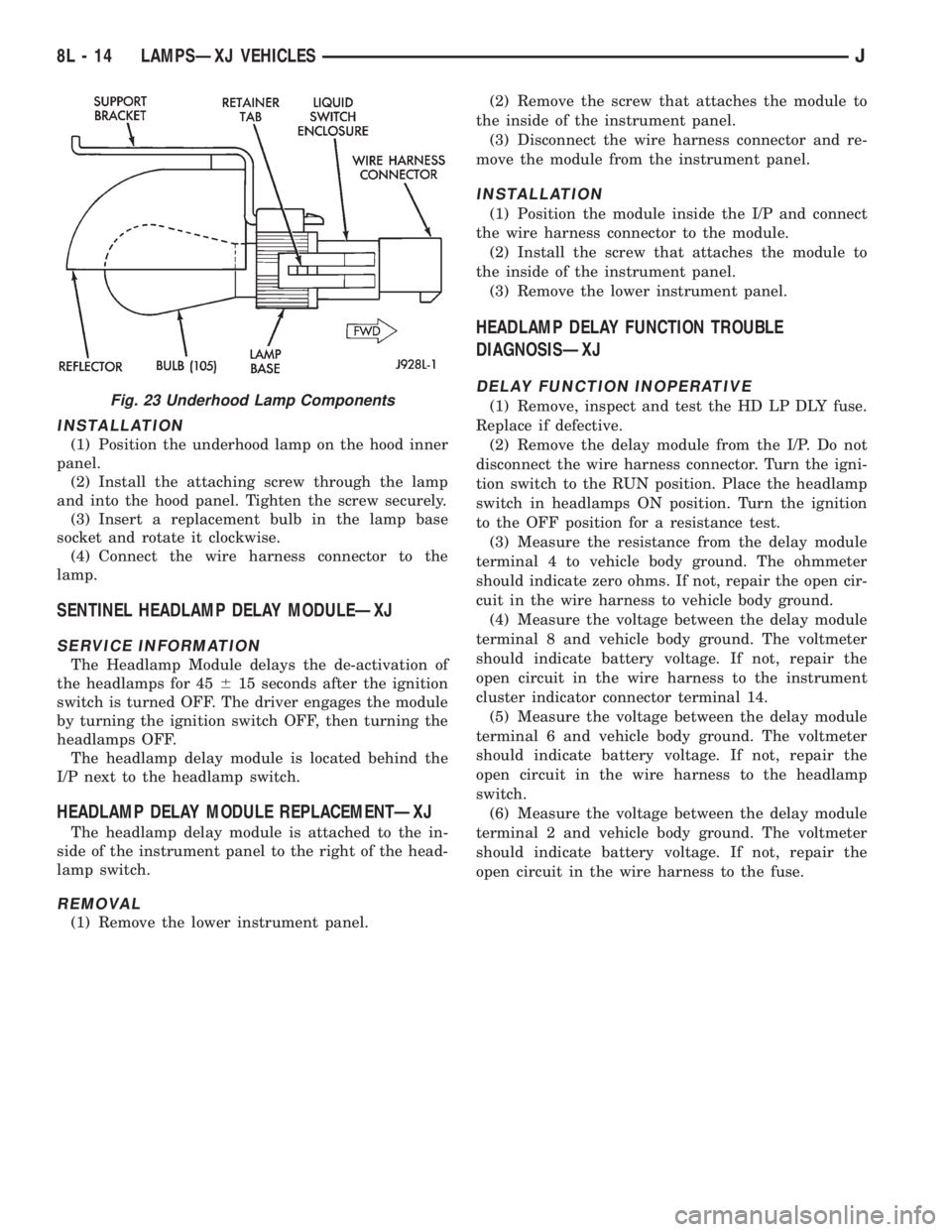
open circuit in the wire harness to the fuse.Fig. 23 Underhood Lamp Components
8L - 14 LAMPSÐXJ VEHICLESJ
Page 476 of 2158

INTERIOR LAMPS
INDEX
page page
Dome Lamp ReplacementÐXJ............... 17
Dome/Courtesy Lamp Service InformationÐXJ . . . 16
Dome/Courtesy Lamp Trouble DiagnosisÐXJ.... 16Lighted Vanity Mirror Trouble DiagnosisÐXJ..... 16
Lighted Vanity MirrorÐXJ................... 16
Overhead ConsoleÐXJ..................... 17
DOME/COURTESY LAMP SERVICE
INFORMATIONÐXJ
Voltage is applied at all times via the dome lamp
fuse to each of the interior lamp bulbs. The interior
lamp bulbs illuminate when they are connected to
body ground via the switch:
²Headlamp switch.
²Glove box switch.
²Door pillar switch.
²Liftgate switch (if the cargo lamp is ON).
If equipped with Security Alarm Module, refer to
Group 8Q, Vehicle Theft Security System.
DOME/COURTESY LAMP TROUBLE DIAGNOSISÐ
XJ
ALL LAMPS INOPERATIVE
(1) Rotate the headlamp switch rheostat clockwise.
The lamps should light. If not OK, remove, inspect
and test the dome lamp fuse. Replace if bad.
(2) If the fuse is OK, repair the open circuit in the
wire harness to vehicle body ground.
ONE LAMP INOPERATIVE
(1) Measure the resistance across the bulb holder
terminals. The ohmmeter should indicate zero ohms.
If not, replace the bulb.
(2) Measure the voltage between the voltage side
of the bulb holder and vehicle body ground. The volt-
meter should indicate battery voltage. If not, repair
the open circuit in the wire harness to the splice.
LAMPS INOPERATIVE WITH ONE OR MORE
DOORS OPENED
(1) Remove the inoperative switch from the door
pillar and connect the switch wire directly to ground.
The lamp should light.
(2) If not, check for an open circuit in black
(ground) wire. Repair as necessary. If lamps still do
not light, replace the switch.
LIGHTED VANITY MIRRORÐXJ
SERVICE INFORMATION
Both the driver and the front passenger sunvisor
can be equipped with a lighted vanity mirror. A lamplocated at each side of the vanity mirror. The lamps
are switched ON automatically when the mirror
cover is lifted (Fig. 1).
Voltage is applied directly to the vanity lamp bulbs
via the dome lamp fuse.
LIGHTED VANITY MIRROR TROUBLE
DIAGNOSISÐXJ
VANITY LAMPS INOPERATIVE
(1) Remove, inspect and test the dome lamp fuse.
Replace if defective.
(2) Test the dome lamp operation. If OK, go to the
next step. If not OK, repair the open circuit in the
wire harness from the splice.
(3) Measure the voltage between the pink wire on
the switch connector and vehicle body ground. The
voltmeter should indicate battery voltage. If not OK,
repair the open circuit in the wire harness from the
splice.
(4) Connect a jumper wire from the ground side of
the switch to a good vehicle body ground. Measure
the resistance to vehicle body ground. The ohmmeter
should indicate zero ohms. If not, repair the open cir-
cuit in the wire harness to vehicle body ground.
Fig. 1 Lighted Vanity Mirror
8L - 16 LAMPSÐXJ VEHICLESJ
Page 486 of 2158

HEADLAMP SWITCHÐYJ
To remove or replace the headlamp switch, refer to
Group 8E, Instrument Panel and Gauges.
FOG LAMP SWITCH REPLACEMENTÐYJ
REMOVAL
The fog lamp switch is located on the instrument
panel at the right of the steering column. The fog
lamp circuit relay is located below the left headlamp.
(1) Disconnect the battery negative cable.
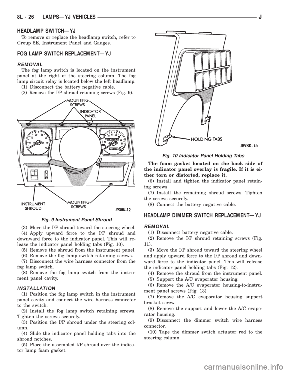
(2) Remove the I/P shroud retaining screws (Fig. 9).
(3) Move the I/P shroud toward the steering wheel.
(4) Apply upward force to the I/P shroud and
downward force to the indicator panel. This will re-
lease the indicator panel holding tabs (Fig. 10).
(5) Remove the shroud from the instrument panel.
(6) Remove the fog lamp switch retaining screws.
(7) Disconnect the wire harness connector from the
fog lamp switch.
(8) Remove the fog lamp switch from the instru-
ment panel cavity.
INSTALLATION
(1) Position the fog lamp switch in the instrument
panel cavity and connect the wire harness connector
to the switch.
(2) Install the fog lamp switch retaining screws.
Tighten the screws securely.
(3) Position the I/P shroud under the steering col-
umn.
(4) Slide the indicator panel holding tabs into the
shroud notches.
(5) Place the assembled I/P shroud over the indica-
tor lamp foam gasket.The foam gasket located on the back side of
the indicator panel overlay is fragile. If it is ei-
ther torn or distorted, replace it.
(6) Install and tighten the indicator panel retain-
ing screws.
(7) Install the remaining shroud screws. Tighten
the screws securely.
(8) Connect the battery negative cable.
HEADLAMP DIMMER SWITCH REPLACEMENTÐYJ
REMOVAL
(1) Disconnect battery negative cable.
(2) Remove the I/P shroud retaining screws (Fig.
11).
(3) Move the I/P shroud toward the steering wheel
and apply upward force to the I/P shroud and down-
ward force to the indicator panel. This will release
the indicator panel holding tabs (Fig. 12).
(4) Remove the shroud from the instrument panel.
(5) Support the A/C evaporator housing.
(6) Remove the A/C evaporator housing-to-instru-
ment panel screws (Fig. 13).
(7) Remove the A/C evaporator housing support
bracket screw.
(8) Remove the support and lower the A/C evapo-
rator housing.
(9) Disconnect the dimmer switch wire harness
connector.
(10) Tape the dimmer switch actuator rod to the
steering column.
Fig. 9 Instrument Panel Shroud
Fig. 10 Indicator Panel Holding Tabs
8L - 26 LAMPSÐYJ VEHICLESJ