1995 JEEP YJ battery replacement
[x] Cancel search: battery replacementPage 491 of 2158
INTERIOR LAMPS
INDEX
page page
Dome/Courtesy Lamp Service InformationÐYJ . . . 31
Dome/Courtesy Lamp Trouble DiagnosisÐYJ.... 31Hardtop Dome/Cargo Lamp Bulb ReplacementÐYJ
Vehicles............................... 31
DOME/COURTESY LAMP SERVICE
INFORMATIONÐYJ
The dome/cargo and underpanel courtesy lamps are
controlled via ON/OFF switches. The ON/OFF
switches are in the lamp ground circuits. Voltage via
the dome/courtesy lamp fuse is applied directly to the
lamp bulbs. When either door is opened, the door pil-
lar switch contacts close and provide a direct path to
vehicle body ground.
The dome/cargo and underpanel courtesy lamps
can also be turned on via the interior lamp illumina-
tion rheostat.
DOME/COURTESY LAMP TROUBLE DIAGNOSISÐ
YJ
ALL LAMPS INOPERATIVE FROM INTERIOR
LAMP ILLUMINATION RHEOSTAT
(1) Rotate the interior lamp illumination rheostat
in an upward direction. The lamps should light. If
not OK, remove, inspect and test the dome lamp
fuse. Replace if bad.
(2) If the fuse is OK, repair the open circuit in the
wire harness to vehicle body ground.
(3) If lamp still does not light, replace the switch.
ONE LAMP INOPERATIVE
(1) Measure the resistance across the bulb holder
terminals. The ohmmeter should indicate zero ohms.
If not, replace the bulb.
(2) Measure the voltage between the voltage side
of the bulb holder and vehicle body ground. The volt-
meter should indicate battery voltage. If not, repair
the open circuit in the wire harness to the splice.
LAMPS INOPERATIVE WITH ONE OR MORE
DOORS OPENED
(1) Remove the inoperative switch from the door
pillar and connect the switch wire directly to ground.
The lamp should light.(2) If not, check for an open circuit in black
(ground) wire. Repair as necessary. If lamps still do
not light, replace the switch.
HARDTOP DOME/CARGO LAMP BULB
REPLACEMENTÐYJ VEHICLES
REMOVAL
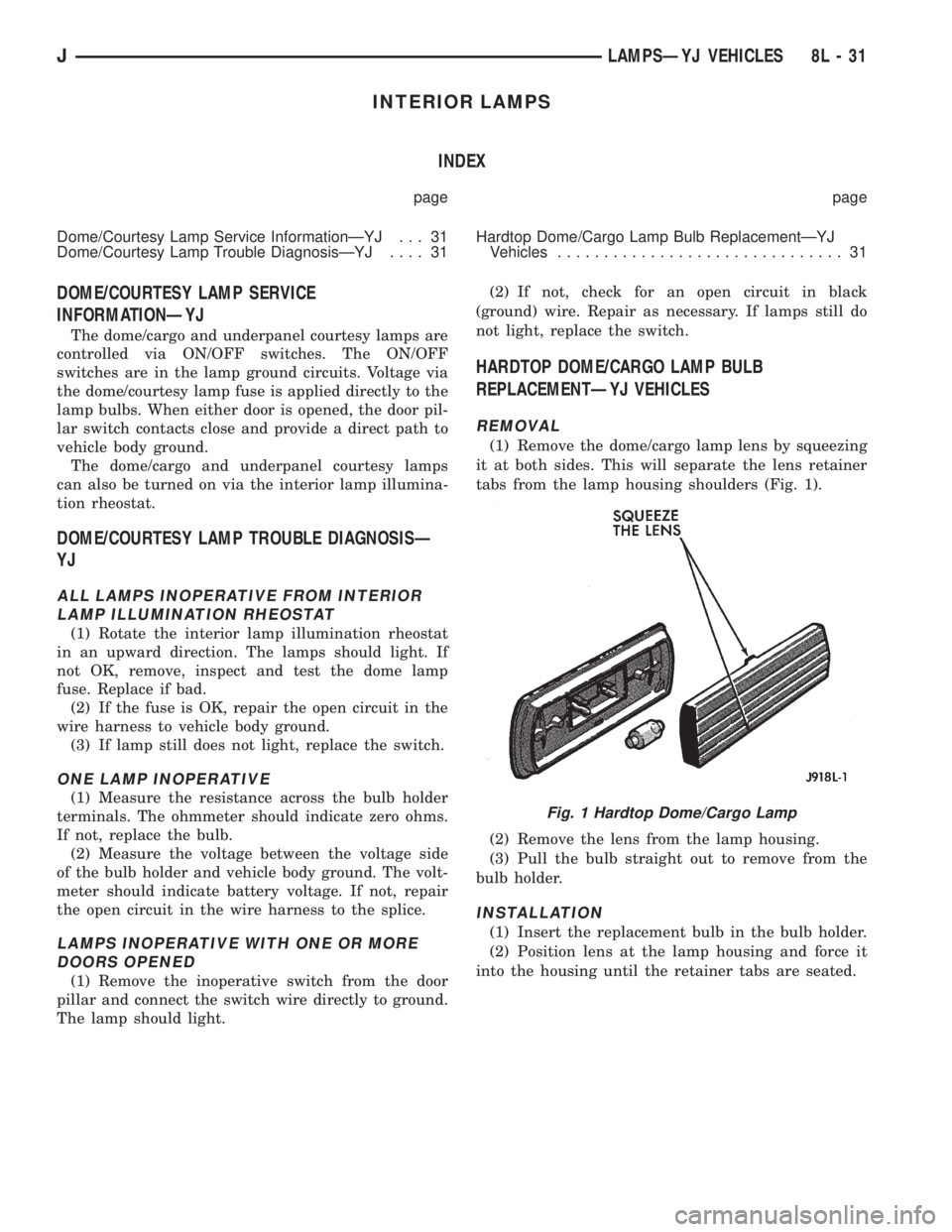
(1) Remove the dome/cargo lamp lens by squeezing
it at both sides. This will separate the lens retainer
tabs from the lamp housing shoulders (Fig. 1).
(2) Remove the lens from the lamp housing.
(3) Pull the bulb straight out to remove from the
bulb holder.
INSTALLATION
(1) Insert the replacement bulb in the bulb holder.
(2) Position lens at the lamp housing and force it
into the housing until the retainer tabs are seated.
Fig. 1 Hardtop Dome/Cargo Lamp
JLAMPSÐYJ VEHICLES 8L - 31
Page 499 of 2158
DEFOGGER SWITCH
With defogger switch connector separated from de-
fogger switch; turn ignition switch to ON for voltage
tests, or turn ignition switch to OFF for resistance
tests.
(1) Measure voltage at defogger switch connector
terminal D. The meter should read approximately 5
volts momentarily. If OK, go to next step. If not OK,
repair open from relay.
(2) Refer to switch diagram for resistance tests. If
not OK, replace defogger switch.
DEFOGGER RELAY
With defogger relay connector separated from de-
fogger relay; turn ignition switch to ON for voltage
tests, or turn ignition switch to OFF for resistance
tests.
(1) Measure voltage at relay connector terminal 4.
The meter should read battery voltage. If OK, go to
next step. If not OK, repair open from fuse 18 (XJ) or
fuse 9 (YJ).(2) Measure voltage at relay connector terminal 5.
The meter should read battery voltage. If OK, go to
next step. If not OK, repair open from fuse 8 (XJ), or
fuse 6 (YJ).
(3) Measure resistance between relay connector
terminal 1 and left side (driver's side) of defogger
grid. The meter should read zero ohms. If OK, go to
next step. If not OK, repair open between relay con-
nector and left side of defogger grid.
(4) Measure resistance between relay connector
terminal 2 and a clean chassis ground. The meter
should read zero ohms. If OK, go to next step. If not
OK, repair open between relay connector and ground.
(5) Connect relay connector and measure voltage
at terminal 3. The meter should read approximately
5 volts. If not OK, replace defogger relay.
SERVICE PROCEDURES
REAR WINDOW GLASS GRID REPAIRS
The repair of grid lines, bus bars or pigtail wires
can be accomplished using the MOPAR Rear Window
Defogger Repair Kit (P/N 4267922) or equivalent.
WARNING: MATERIALS CONTAINED IN REPAIR KIT
MAY CAUSE SKIN OR EYE IRRITATION. CONTAINS
EPOXY RESIN AND AMINE TYPE HARDENER,
HARMFUL IF SWALLOWED. AVOID CONTACT WITH
SKIN AND EYES. FOR SKIN, WASH AFFECTED AR-
EAS WITH SOAP AND WATER. DO NOT TAKE IN-
TERNALLY. IF TAKEN INTERNALLY, INDUCE
VOMITING; CALL A PHYSICIAN IMMEDIATELY. IF IN
CONTACT WITH EYES, FLUSH WITH PLENTY OF
WATER. USE WITH ADEQUATE VENTILATION. DO
NOT USE NEAR FIRE OR FLAME. CONTENTS CON-
TAIN 3% FLAMMABLE SOLVENTS. KEEP OUT OF
REACH OF CHILDREN.
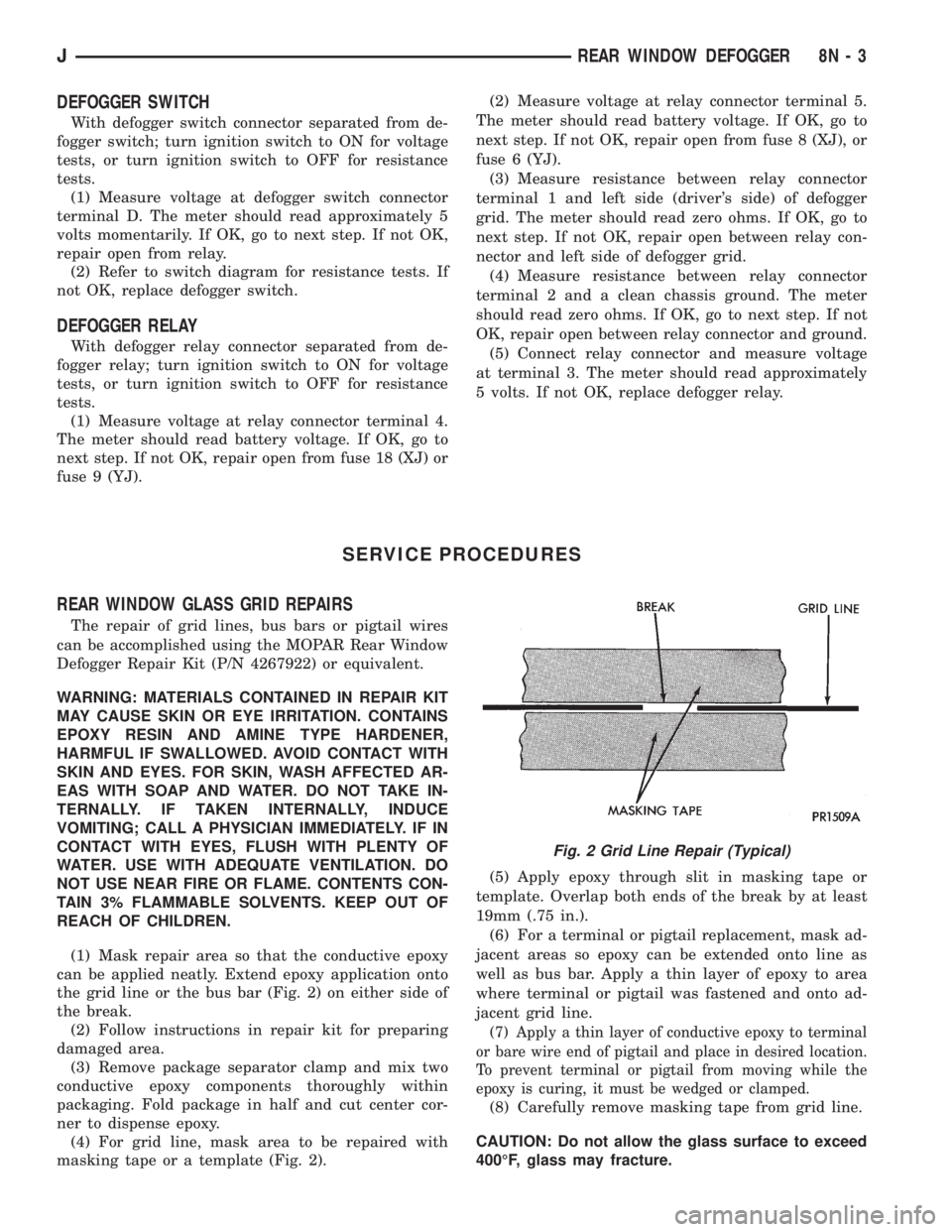
(1) Mask repair area so that the conductive epoxy
can be applied neatly. Extend epoxy application onto
the grid line or the bus bar (Fig. 2) on either side of
the break.
(2) Follow instructions in repair kit for preparing
damaged area.
(3) Remove package separator clamp and mix two
conductive epoxy components thoroughly within
packaging. Fold package in half and cut center cor-
ner to dispense epoxy.
(4) For grid line, mask area to be repaired with
masking tape or a template (Fig. 2).(5) Apply epoxy through slit in masking tape or
template. Overlap both ends of the break by at least
19mm (.75 in.).
(6) For a terminal or pigtail replacement, mask ad-
jacent areas so epoxy can be extended onto line as
well as bus bar. Apply a thin layer of epoxy to area
where terminal or pigtail was fastened and onto ad-
jacent grid line.
(7) Apply a thin layer of conductive epoxy to terminal
or bare wire end of pigtail and place in desired location.
To prevent terminal or pigtail from moving while the
epoxy is curing, it must be wedged or clamped.
(8) Carefully remove masking tape from grid line.
CAUTION: Do not allow the glass surface to exceed
400ÉF, glass may fracture.
Fig. 2 Grid Line Repair (Typical)
JREAR WINDOW DEFOGGER 8N - 3
Page 525 of 2158

POWER MIRRORS
CONTENTS
page page
DIAGNOSIS............................. 1
GENERAL INFORMATION.................. 1SERVICE PROCEDURES................... 4
GENERAL INFORMATION
Power outside rear view mirrors are an available
option on XJ (Cherokee) models. Following are gen-
eral descriptions of the major components in the
power mirror system. Refer to Group 8W - Wiring Di-
agrams for complete circuit descriptions and dia-
grams.
POWER MIRROR
The power mirrors are connected to battery feed at
all times. Each mirror head contains two electric mo-
tors, two drive mechanisms and the mirror glass.
One motor and drive controls mirror up-and-down
movement, and the other controls right-and-left
movement.
The mirror glass is the only serviced replacement
part for the power mirror assembly. If any other com-ponent of the mirror unit is faulty or damaged, the
entire assembly must be replaced.
POWER MIRROR SWITCH
Both the right and left mirror are controlled by a
multi-function switch located on the front of the cen-
ter console storage compartment, directly below the
armrest. The selector switch is moved right (right
mirror control), left (left mirror control), or center to
turn power mirrors off. Then one of four directional
control buttons is depressed to control movement of
the selected mirror up, down, right, or left. The
power mirror switch is serviced only as a complete
unit.
DIAGNOSIS
POWER MIRROR SYSTEM
(1) Check fuse 16 in Power Distribution Center
(PDC) and fuse 9 in fuseblock module. If OK, go to
next step. If not OK, replace fuse.
(2) Check for battery voltage at fuse 9 in fuseblock
module. If OK, go to next step. If not OK, repair cir-
cuit to fuse 16 in PDC.
(3) Remove power mirror switch from the center
console. See Power Mirror Switch Remove/Install.
(4) Disconnect wiring harness connector from
switch. Check for battery voltage at pink wire. If OK,
go to next step. If not OK, repair circuit to fuse 9 in
fuseblock module.
(5) Check for continuity between black wire in
switch harness connector and a good ground. There
should be continuity. If OK, go to next step. If not
OK, repair circuit to ground.
(6) Check switch continuity as shown in the Mirror
Switch Continuity charts. If OK, go to next step. If
not OK, replace switch.(7) See Power Mirror Switch illustration. Connect
a jumper wire from mirror switch connector cavity
for pin E to cavity for pin F. Now connect a second
jumper from connector cavity for pin G to each of the
following pin cavities: A, B, C, then D. In each case,
the selected mirror head should move. If OK, replace
switch. If not OK, go to next step.
(8) Remove door trim panel and unplug power mir-
ror connector inside door. Connect one jumper wire to
a good ground and a second jumper wire to a battery
feed. Connect other ends of jumpers to the mirror
side of connector in door (refer to Group 8W - Wiring
Diagrams for connector cavity identification). Mirror
head should move in each of the four directions. If
OK, repair wiring between mirror switch and door
connectors. If not OK, replace mirror.
JPOWER MIRRORS 8T - 1
Page 531 of 2158
CHIME/BUZZER WARNING SYSTEMS
CONTENTS
page page
DIAGNOSIS............................. 2
GENERAL INFORMATION.................. 1SERVICE PROCEDURES................... 4
GENERAL INFORMATION
This group covers the buzzer warning system,
which is standard equipment on XJ (Cherokee)/YJ
(Wrangler) models. The system provides an audible
warning to the driver when it monitors the following
conditions:
²key is in ignition switch with the driver's door
open
²head or park lamps are on with driver's door open
(XJ only)
²driver's seat belt is not buckled with ignition
switch in ON position.
Following are general descriptions of the major
components in the buzzer warning system. Refer to
Group 8W - Wiring Diagrams for complete circuit de-
scriptions and diagrams.
BUZZER MODULE
The buzzer module is located in the fuseblock mod-
ule under the left end of the instrument panel. It re-
ceives battery voltage at all times from (fuse 15 - XJ,
fuse 3 - YJ) the fuseblock module. It also receives a
second battery feed (fuse 17 - XJ, fuse 9 - YJ) when
the ignition switch is in the ON or START position.
Other inputs to the module include the driver's door
jamb switch, the driver's seat belt switch, the ignition
key-in switch, and the headlamp switch (XJ only). The
only output of the module is a timed 4 to 8 second feed
to the seat belt reminder lamp in the message center of
the instrument cluster. The timer function begins after
the ignition switch is turned to the ON position.
The buzzer module can not be repaired. If faulty, it
must be replaced.
DRIVER'S DOOR JAMB SWITCH
The driver's door jamb switch is mounted to the
driver's door hinge pillar. The switch closes a path to
ground for the buzzer module through the key-in
switch or headlamp switch (XJ only) when the driv-
er's door is opened, and opens when the driver's door
is closed. This switch can not be repaired. If faulty, it
must be replaced.
IGNITION KEY-IN SWITCH
XJ MODELS
The key-in switch is integral to the ignition switch,
which is mounted on the right side of the steering col-
umn. It closes a path to ground for the buzzer module
when the ignition key is inserted in the ignition lock cyl-
inder and the driver's door jamb switch is closed (door
open). The switch opens when the key is removed from
the ignition lock cylinder. This switch can not be re-
paired. If faulty, the entire ignition switch must be re-
placed. Refer to Group 8D - Ignition Systems for service
procedures.
YJ MODELS
The key-in switch is mounted within the steering col-
umn in the lock cylinder housing. It closes a path to
ground for the buzzer module when the ignition key is
inserted in the ignition lock cylinder and the driver's
door jamb switch is closed (door open). The switch opens
when the key is removed from the ignition lock cylinder.
This switch is available for service replacement. Refer
to Group 19 - Steering for service procedures.
HEADLAMP SWITCH (XJ ONLY)
The headlamp switch is located in the instrument
panel. It closes a path to ground for the buzzer module
when the park or headlamps are on and the driver's
door jamb switch is closed (door open). The switch opens
the ground path when the park and headlamps are
turned off. The headlamp switch can not be repaired. If
faulty, it must be replaced. Refer to Group 8E - Instru-
ment Panel and Gauges for service procedures.
DRIVER'S SEAT BELT SWITCH
The driver's seat belt switch is integral to the driv-
er's seat belt buckle-half assembly. The switch is nor-
mally closed, providing a ground path to the buzzer
module. When the tip-half of the seat belt is inserted
into the seat belt buckle, the switch opens the buzzer
module ground path. The seat belt switch can not be
repaired. If faulty, the entire driver's seat belt buck-
le-half must be replaced. Refer to Group 23 - Body
Components for service procedures.
JCHIME/BUZZER WARNING SYSTEMS 8U - 1
Page 535 of 2158
WIRING DIAGRAMSÐGENERAL INFORMATION
INDEX
page page
Circuit Identification......................... 1
Connector and Terminal Replacement........... 7
Connector Replacement..................... 6
Connectors............................... 2
Diode Replacement........................ 8
Electrostatic Discharge (ESC) Sensitive Devices . . . 2
General Information......................... 1
Intermittent and Poor Connections.............. 4
Notes, Cautions, and Warnings................ 1Symbols................................. 2
Take Outs................................ 2
Terminal Replacement....................... 8
Terminal/Connector RepairÐMolex Connectors.... 6
Troubleshooting Tests....................... 4
Troubleshooting Tools....................... 4
Troubleshooting Wiring Problems.............. 5
Wire Code Identification..................... 1
Wiring Repair............................. 6
GENERAL INFORMATION
This Group is divided into three stand alone sec-
tions; XJ, YJ, and XJ Right Hand Drive (XJ-RHD).
Separate circuit descriptions and wiring diagrams are
provided for each vehicle. Each section contains a
Contents list for the wiring diagrams and circuit de-
scriptions for that vehicle.
The complete XJ circuit descriptions and diagrams
are printed first, followed by those for the YJ and
then the XJ-RHD. The heading at the top of each
page identifies the vehicle covered in the section.
NOTES, CAUTIONS, and WARNINGS
Throughout this group additional important infor-
mation is presented in three ways; Notes, Cautions,
and Warnings.
NOTESare used to help describe how switches or
components operate to complete a particular circuit.
They are also used to indicate different conditions
that may appear on the vehicle. For example, an
up-to and after condition.
CAUTIONSare used to indicate information that
could prevent making an error that may damage the
vehicle.
WARNINGSprovide information to prevent per-
sonal injury and vehicle damage. Below is a list of
general warnings that should be followed any time a
vehicle is being serviced.
ALWAYS WEAR SAFETY GLASSES FOR EYE PRO-
TECTION.
USE SAFETY STANDS ANYTIME A PROCEDURE RE-
QUIRES BEING UNDER A VEHICLE.
BE SURE THAT THE IGNITION SWITCH ALWAYS IS
IN THE OFF POSITION, UNLESS THE PROCEDURE
REQUIRES IT TO BE ON.SET THE PARKING BRAKE WHEN WORKING ON
ANY VEHICLE. AN AUTOMATIC TRANSMISSION
SHOULD BE IN PARK. A MANUAL TRANSMISSION
SHOULD BE IN NEUTRAL.
OPERATE THE ENGINE ONLY IN A WELL-VENTI-
LATED AREA.
KEEP AWAY FROM MOVING PARTS WHEN THE EN-
GINE IS RUNNING, ESPECIALLY THE FAN AND BELTS.
TO PREVENT SERIOUS BURNS, AVOID CONTACT
WITH HOT PARTS SUCH AS THE RADIATOR, EX-
HAUST MANIFOLD(S), TAIL PIPE, CATALYTIC CON-
VERTER, AND MUFFLER.
DO NOT ALLOW FLAME OR SPARKS NEAR THE
BATTERY. GASES ARE ALWAYS PRESENT IN AND
AROUND THE BATTERY.
ALWAYS REMOVE RINGS, WATCHES, LOOSE
HANGING JEWELRY, AND LOOSE CLOTHING.
WIRE CODE IDENTIFICATION
Each wire shown in the diagrams contains a code
(Fig. 1) which identifies the main circuit, part of the
main circuit, gauge of wire, and color. The color is
shown as a two letter code which can be identified by
referring to the Wire Color Code Chart (Fig. 2).
CIRCUIT IDENTIFICATION
All circuits in the diagrams use an alpha/numeric
code to identify the wire and its function (Fig. 3). To
identify which circuit code applies to a system, refer
to the Circuit Identification Code Chart. This chart
shows the main circuits only and does not show the
secondary codes that may apply to some models.
JWIRING DIAGRAMSÐGENERAL INFORMATION 8W - 1
Page 540 of 2158
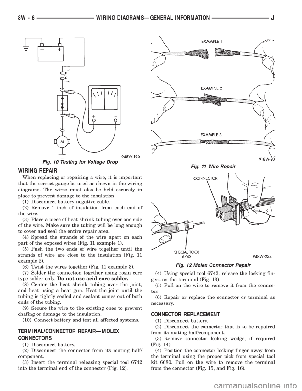
WIRING REPAIR
When replacing or repairing a wire, it is important
that the correct gauge be used as shown in the wiring
diagrams. The wires must also be held securely in
place to prevent damage to the insulation.
(1) Disconnect battery negative cable.
(2) Remove 1 inch of insulation from each end of
the wire.
(3) Place a piece of heat shrink tubing over one side
of the wire. Make sure the tubing will be long enough
to cover and seal the entire repair area.
(4) Spread the strands of the wire apart on each
part of the exposed wires (Fig. 11 example 1).
(5) Push the two ends of wire together until the
strands of wire are close to the insulation (Fig. 11
example 2).
(6) Twist the wires together (Fig. 11 example 3).
(7) Solder the connection together using rosin core
type solder only.Do not use acid core solder.
(8) Center the heat shrink tubing over the joint,
and heat using a heat gun. Heat the joint until the
tubing is tightly sealed and sealant comes out of both
ends of the tubing.
(9) Secure the wire to the existing ones to prevent
chafing or damage to the insulation.
(10) Connect battery and test all affected systems.
TERMINAL/CONNECTOR REPAIRÐMOLEX
CONNECTORS
(1) Disconnect battery.
(2) Disconnect the connector from its mating half/
component.
(3) Insert the terminal releasing special tool 6742
into the terminal end of the connector (Fig. 12).(4) Using special tool 6742, release the locking fin-
gers on the terminal (Fig. 13).
(5) Pull on the wire to remove it from the connec-
tor.
(6) Repair or replace the connector or terminal as
necessary.
CONNECTOR REPLACEMENT
(1) Disconnect battery.
(2) Disconnect the connector that is to be repaired
from its mating half/component.
(3) Remove connector locking wedge, if required
(Fig. 14).
(4) Position the connector locking finger away from
the terminal using the proper pick from special tool
kit 6680. Pull on the wire to remove the terminal
from the connector (Fig. 15, and Fig. 16).
Fig. 10 Testing for Voltage DropFig. 11 Wire Repair
Fig. 12 Molex Connector Repair
8W - 6 WIRING DIAGRAMSÐGENERAL INFORMATIONJ
Page 541 of 2158

(5) Reset the terminal locking tang, if it has one.
(6) Insert the removed wire in the same cavity on
the repair connector.
(7) Repeat steps four through six for each wire in
the connector, being sure that all wires are inserted
into the proper cavities. For additional connector pin-
out identification, refer to the wiring diagrams.
(8) Insert the connector locking wedge into the re-
paired connector, if required.
(9) Connect connector to its mating half/component.
(10) Connect battery and test all affected systems.
CONNECTOR AND TERMINAL REPLACEMENT
(1) Disconnect battery.
(2) Disconnect the connector (that is to be repaired)
from its mating half/component.
(3) Cut off the existing wire connector directly be-
hind the insulator. Remove six inches of tape from the
harness.
(4) Stagger cut all wires on the harness side at 1/2
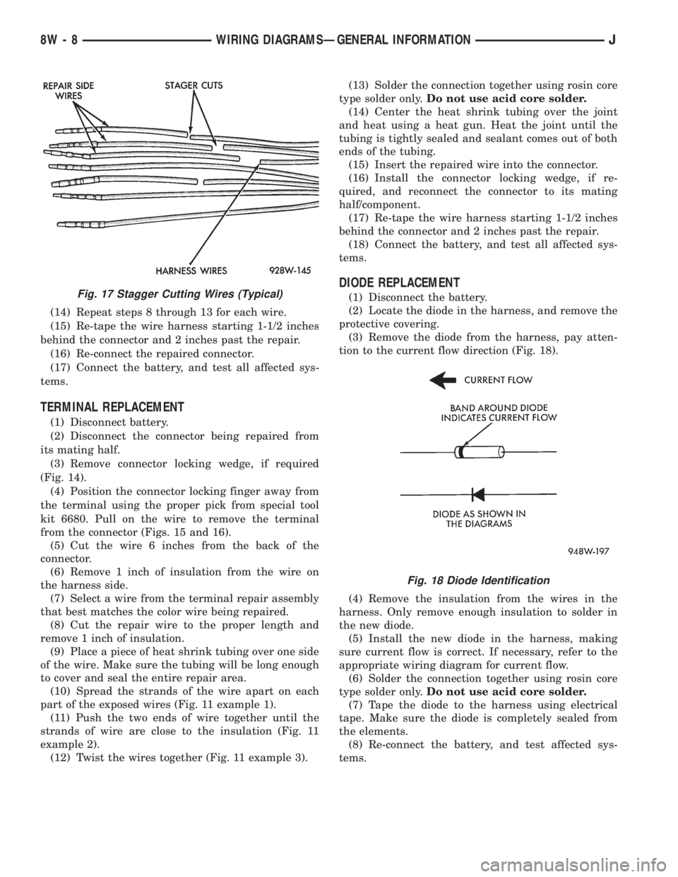
inch intervals (Fig. 17).(5) Remove 1 inch of insulation from each wire on
the harness side.
(6) Stagger cut the matching wires on the repair
connector assembly in the opposite order as was done
on the harness side of the repair. Allow extra length
for soldered connections. Check that the overall
length is the same as the original (Fig. 17).
(7) Remove 1 inch of insulation from each wire.
(8) Place a piece of heat shrink tubing over one side
of the wire. Be sure the tubing will be long enough to
cover and seal the entire repair area.
(9) Spread the strands of the wire apart on each
part of the exposed wires (Fig. 11 example 1).
(10) Push the two ends of wire together until the
strands of wire are close to the insulation (Fig. 11
example 2).
(11) Twist the wires together (Fig. 11 example 3).
(12) Solder the connection together using rosin core
type solder only.Do not use acid core solder.
(13) Center the heat shrink tubing over the joint
and heat using a heat gun. Heat the joint until the
tubing is tightly sealed and sealant comes out of both
ends of the tubing.
Fig. 13 Using Special Tool 6742
Fig. 14 Connector Locking Wedge Tab (Typical)
Fig. 15 Terminal Removal
Fig. 16 Terminal Removal Using Special Tool
JWIRING DIAGRAMSÐGENERAL INFORMATION 8W - 7
Page 542 of 2158
(14) Repeat steps 8 through 13 for each wire.
(15) Re-tape the wire harness starting 1-1/2 inches
behind the connector and 2 inches past the repair.
(16) Re-connect the repaired connector.
(17) Connect the battery, and test all affected sys-
tems.
TERMINAL REPLACEMENT
(1) Disconnect battery.
(2) Disconnect the connector being repaired from
its mating half.
(3) Remove connector locking wedge, if required
(Fig. 14).
(4) Position the connector locking finger away from
the terminal using the proper pick from special tool
kit 6680. Pull on the wire to remove the terminal
from the connector (Figs. 15 and 16).
(5) Cut the wire 6 inches from the back of the
connector.
(6) Remove 1 inch of insulation from the wire on
the harness side.
(7) Select a wire from the terminal repair assembly
that best matches the color wire being repaired.
(8) Cut the repair wire to the proper length and
remove 1 inch of insulation.
(9) Place a piece of heat shrink tubing over one side
of the wire. Make sure the tubing will be long enough
to cover and seal the entire repair area.
(10) Spread the strands of the wire apart on each
part of the exposed wires (Fig. 11 example 1).
(11) Push the two ends of wire together until the
strands of wire are close to the insulation (Fig. 11
example 2).
(12) Twist the wires together (Fig. 11 example 3).(13) Solder the connection together using rosin core
type solder only.Do not use acid core solder.
(14) Center the heat shrink tubing over the joint
and heat using a heat gun. Heat the joint until the
tubing is tightly sealed and sealant comes out of both
ends of the tubing.
(15) Insert the repaired wire into the connector.
(16) Install the connector locking wedge, if re-
quired, and reconnect the connector to its mating
half/component.
(17) Re-tape the wire harness starting 1-1/2 inches
behind the connector and 2 inches past the repair.
(18) Connect the battery, and test all affected sys-
tems.
DIODE REPLACEMENT
(1) Disconnect the battery.
(2) Locate the diode in the harness, and remove the
protective covering.
(3) Remove the diode from the harness, pay atten-
tion to the current flow direction (Fig. 18).
(4) Remove the insulation from the wires in the
harness. Only remove enough insulation to solder in
the new diode.
(5) Install the new diode in the harness, making
sure current flow is correct. If necessary, refer to the
appropriate wiring diagram for current flow.
(6) Solder the connection together using rosin core
type solder only.Do not use acid core solder.
(7) Tape the diode to the harness using electrical
tape. Make sure the diode is completely sealed from
the elements.
(8) Re-connect the battery, and test affected sys-
tems.Fig. 17 Stagger Cutting Wires (Typical)
Fig. 18 Diode Identification
8W - 8 WIRING DIAGRAMSÐGENERAL INFORMATIONJ