1995 JEEP YJ battery replacement
[x] Cancel search: battery replacementPage 1354 of 2158
INSPECTION
Inspect the cam lobes for wear.
Inspect the bearing journals for uneven wear pat-
tern or finish.
Inspect the bearings for wear.
Inspect the distributor drive gear for wear.
If the camshaft appears to have been rubbing
against the timing case cover, examine the oil pres-
sure relief holes in the rear cam journal. The oil
pressure relief holes must be free of debris.
INSTALLATION
(1) Lubricate the camshaft with Mopar Engine Oil
Supplement, or equivalent.
(2) Carefully install the camshaft to prevent dam-
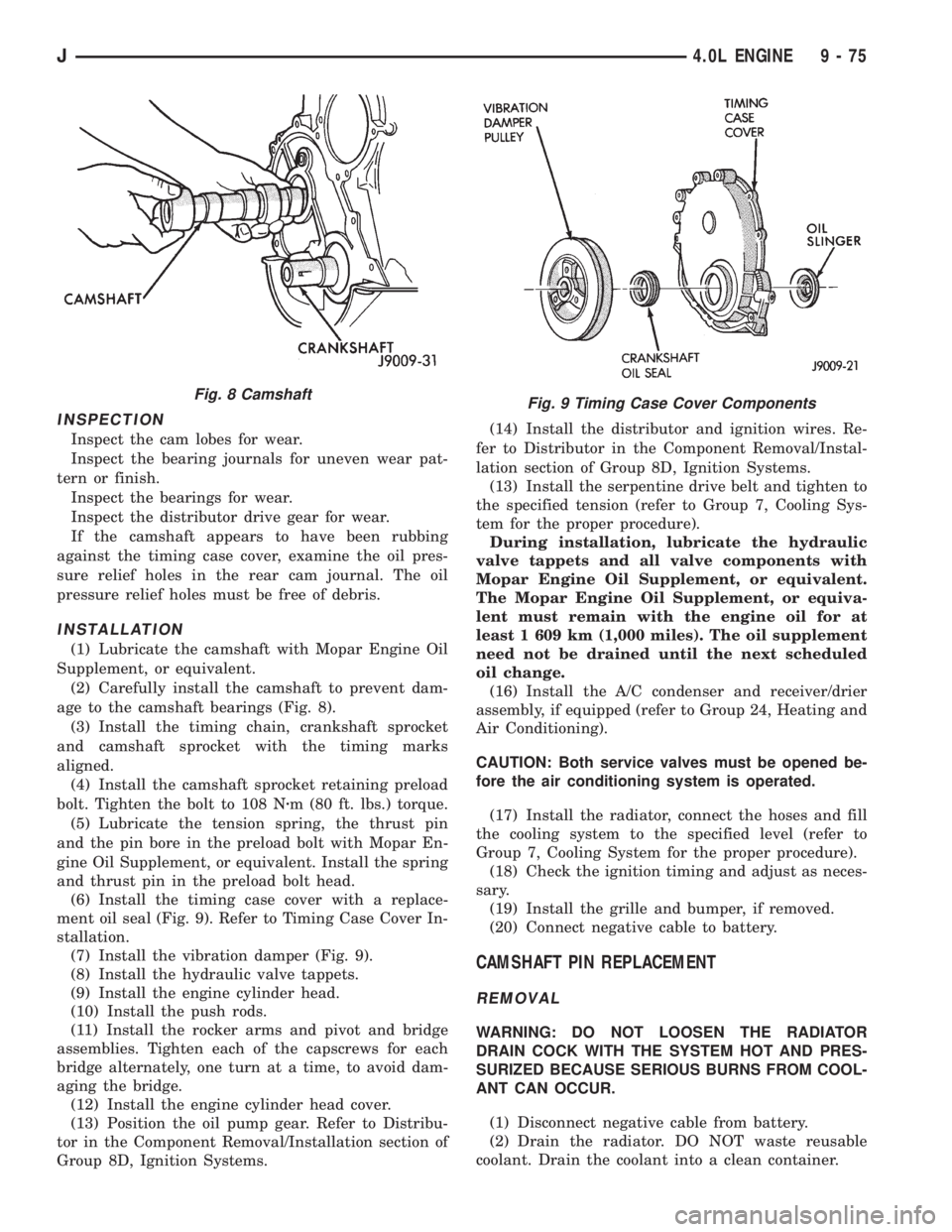
age to the camshaft bearings (Fig. 8).
(3) Install the timing chain, crankshaft sprocket
and camshaft sprocket with the timing marks
aligned.
(4) Install the camshaft sprocket retaining preload
bolt. Tighten the bolt to 108 Nzm (80 ft. lbs.) torque.
(5) Lubricate the tension spring, the thrust pin
and the pin bore in the preload bolt with Mopar En-
gine Oil Supplement, or equivalent. Install the spring
and thrust pin in the preload bolt head.
(6) Install the timing case cover with a replace-
ment oil seal (Fig. 9). Refer to Timing Case Cover In-
stallation.
(7) Install the vibration damper (Fig. 9).
(8) Install the hydraulic valve tappets.
(9) Install the engine cylinder head.
(10) Install the push rods.
(11) Install the rocker arms and pivot and bridge
assemblies. Tighten each of the capscrews for each
bridge alternately, one turn at a time, to avoid dam-
aging the bridge.
(12) Install the engine cylinder head cover.
(13) Position the oil pump gear. Refer to Distribu-
tor in the Component Removal/Installation section of
Group 8D, Ignition Systems.(14) Install the distributor and ignition wires. Re-
fer to Distributor in the Component Removal/Instal-
lation section of Group 8D, Ignition Systems.
(13) Install the serpentine drive belt and tighten to
the specified tension (refer to Group 7, Cooling Sys-
tem for the proper procedure).
During installation, lubricate the hydraulic
valve tappets and all valve components with
Mopar Engine Oil Supplement, or equivalent.
The Mopar Engine Oil Supplement, or equiva-
lent must remain with the engine oil for at
least 1 609 km (1,000 miles). The oil supplement
need not be drained until the next scheduled
oil change.
(16) Install the A/C condenser and receiver/drier
assembly, if equipped (refer to Group 24, Heating and
Air Conditioning).
CAUTION: Both service valves must be opened be-
fore the air conditioning system is operated.
(17) Install the radiator, connect the hoses and fill
the cooling system to the specified level (refer to
Group 7, Cooling System for the proper procedure).
(18) Check the ignition timing and adjust as neces-
sary.
(19) Install the grille and bumper, if removed.
(20) Connect negative cable to battery.
CAMSHAFT PIN REPLACEMENT
REMOVAL
WARNING: DO NOT LOOSEN THE RADIATOR
DRAIN COCK WITH THE SYSTEM HOT AND PRES-
SURIZED BECAUSE SERIOUS BURNS FROM COOL-
ANT CAN OCCUR.
(1) Disconnect negative cable from battery.
(2) Drain the radiator. DO NOT waste reusable
coolant. Drain the coolant into a clean container.
Fig. 9 Timing Case Cover ComponentsFig. 8 Camshaft
J4.0L ENGINE 9 - 75
Page 1356 of 2158
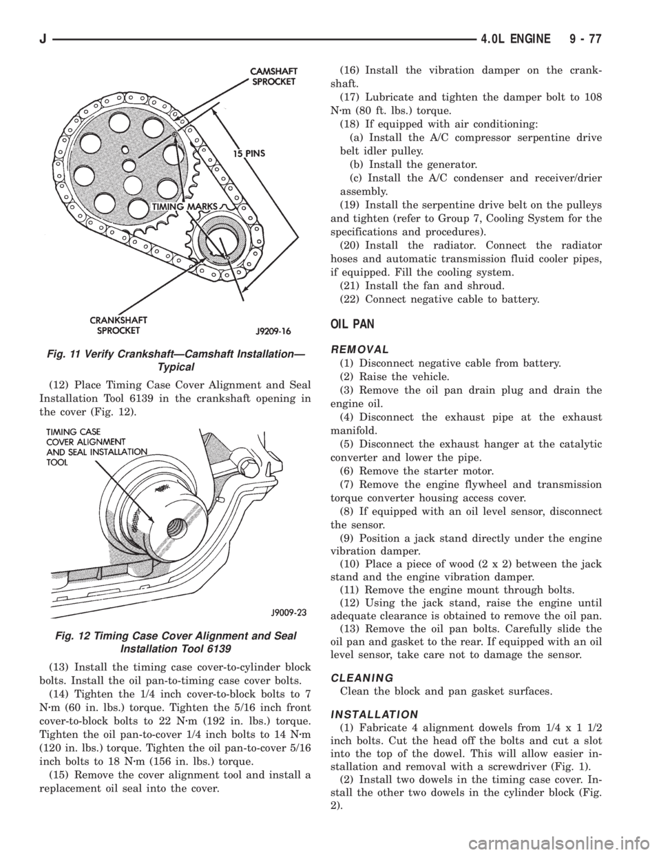
(12) Place Timing Case Cover Alignment and Seal
Installation Tool 6139 in the crankshaft opening in
the cover (Fig. 12).
(13) Install the timing case cover-to-cylinder block
bolts. Install the oil pan-to-timing case cover bolts.
(14) Tighten the 1/4 inch cover-to-block bolts to 7
Nzm (60 in. lbs.) torque. Tighten the 5/16 inch front
cover-to-block bolts to 22 Nzm (192 in. lbs.) torque.
Tighten the oil pan-to-cover 1/4 inch bolts to 14 Nzm
(120 in. lbs.) torque. Tighten the oil pan-to-cover 5/16
inch bolts to 18 Nzm (156 in. lbs.) torque.
(15) Remove the cover alignment tool and install a
replacement oil seal into the cover.(16) Install the vibration damper on the crank-
shaft.
(17) Lubricate and tighten the damper bolt to 108
Nzm (80 ft. lbs.) torque.
(18) If equipped with air conditioning:
(a) Install the A/C compressor serpentine drive
belt idler pulley.
(b) Install the generator.
(c) Install the A/C condenser and receiver/drier
assembly.
(19) Install the serpentine drive belt on the pulleys
and tighten (refer to Group 7, Cooling System for the
specifications and procedures).
(20) Install the radiator. Connect the radiator
hoses and automatic transmission fluid cooler pipes,
if equipped. Fill the cooling system.
(21) Install the fan and shroud.
(22) Connect negative cable to battery.
OIL PAN
REMOVAL
(1) Disconnect negative cable from battery.
(2) Raise the vehicle.
(3) Remove the oil pan drain plug and drain the
engine oil.
(4) Disconnect the exhaust pipe at the exhaust
manifold.
(5) Disconnect the exhaust hanger at the catalytic
converter and lower the pipe.
(6) Remove the starter motor.
(7) Remove the engine flywheel and transmission
torque converter housing access cover.
(8) If equipped with an oil level sensor, disconnect
the sensor.
(9) Position a jack stand directly under the engine
vibration damper.
(10) Place a piece of wood (2 x 2) between the jack
stand and the engine vibration damper.
(11) Remove the engine mount through bolts.
(12) Using the jack stand, raise the engine until
adequate clearance is obtained to remove the oil pan.
(13) Remove the oil pan bolts. Carefully slide the
oil pan and gasket to the rear. If equipped with an oil
level sensor, take care not to damage the sensor.
CLEANING
Clean the block and pan gasket surfaces.
INSTALLATION
(1) Fabricate 4 alignment dowels from 1/4 x 1 1/2
inch bolts. Cut the head off the bolts and cut a slot
into the top of the dowel. This will allow easier in-
stallation and removal with a screwdriver (Fig. 1).
(2) Install two dowels in the timing case cover. In-
stall the other two dowels in the cylinder block (Fig.
2).
Fig. 11 Verify CrankshaftÐCamshaft InstallationÐ
Typical
Fig. 12 Timing Case Cover Alignment and Seal
Installation Tool 6139
J4.0L ENGINE 9 - 77
Page 1368 of 2158
If the clearance exceeds specification using a pair
of 0.051 mm (0.002 inch) undersize bearing inserts,
measure crankshaft journal diameter with a mi-
crometer. If the journal diameter is correct, the
crankshaft bore in the cylinder block may be mis-
aligned, which requires cylinder block replacement or
machining to true bore.
Replace the crankshaft or grind to accept the ap-
propriate undersize bearing inserts if:
²Journal diameters 1 through 6 are less than
63.4517 mm (2.4981 inches)
²Journal 7 diameter is less than 63.4365 mm
(2.4975 inches).
Once the proper clearances have been obtained,
proceed to Crankshaft Main BearingÐInstallation.
MAIN BEARING JOURNAL DIAMETER (CRANKSHAFT
REMOVED)
Remove the crankshaft from the cylinder block (re-
fer to Cylinder Block - Disassemble).
Clean the oil off the main bearing journal.
Determine the maximum diameter of the journal
with a micrometer. Measure at two locations 90É
apart at each end of the journal.
The maximum allowable taper and out of round is
0.013 mm (0.0005 inch). Compare the measured di-
ameter with the journal diameter specification (Main
Bearing Fitting Chart). Select inserts required to ob-
tain the specified bearing-to-journal clearance.
Install the crankshaft into the cylinder block (refer
to Cylinder Block - Assemble and Crankshaft Main
Bearings - Installation).
INSTALLATION
(1) Lubricate the bearing surface of each insert
with engine oil.
(2) Loosen all the main bearing caps. Install the
main bearing upper inserts.
(3) Install the lower bearing inserts into the main
bearing caps.
(4) Install the main bearing cap(s) and lower in-
sert(s).
(5) Tighten the bolts of caps 1, 2, 4, 5, 6, and 7 to
54 Nzm (40 ft. lbs.) torque. Now tighten these bolts to
95 Nzm (70 ft. lbs.) torque. Finally, tighten these
bolts to 108 Nzm (80 ft. lbs.) torque.
(6) Push the crankshaft forward and backward.
Load the crankshaft front or rear and tighten cap
bolt No.3 to 54 Nzm (40 ft. lbs.) torque. Then tighten
to 95 Nzm (70 ft. lbs.) torque and finally tighten to
108 Nzm (80 ft. lbs.) torque.
(7) Rotate the crankshaft after tightening each
main bearing cap to ensure the crankshaft rotates
freely.
(8) Check crankshaft end play. Crankshaft end
play is controlled by the thrust bearing which is
flange and installed at the No.2 main bearing posi-
tion.(a) Attach a magnetic base dial indicator to the
cylinder block at either the front or rear of the en-
gine.
(b) Position the dial indicator rod so that it is
parallel to the center line of the crankshaft.
(c) Pry the crankshaft forward, position the dial
indicator to zero.
(d) Pry the crankshaft forward and backward.
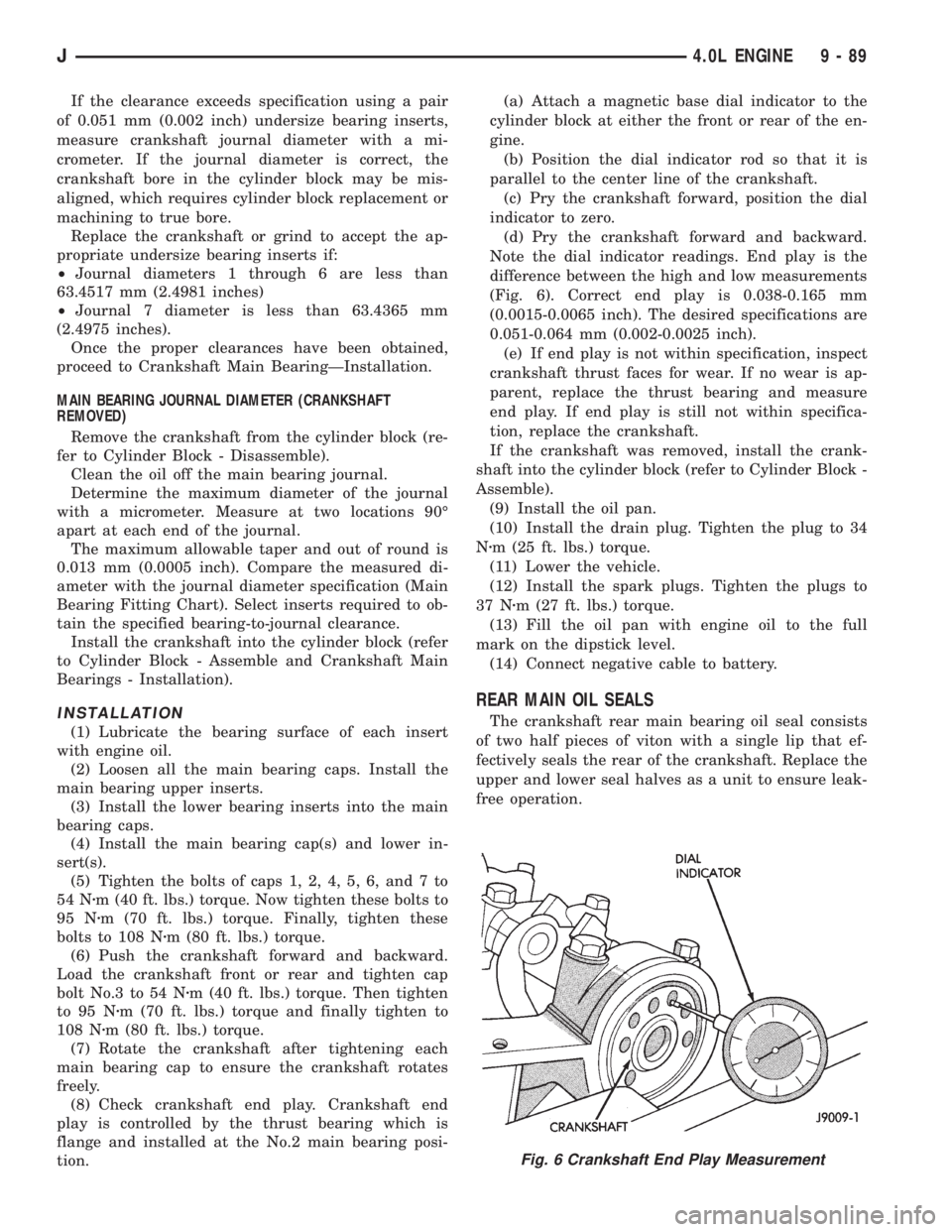
Note the dial indicator readings. End play is the
difference between the high and low measurements
(Fig. 6). Correct end play is 0.038-0.165 mm
(0.0015-0.0065 inch). The desired specifications are
0.051-0.064 mm (0.002-0.0025 inch).
(e) If end play is not within specification, inspect
crankshaft thrust faces for wear. If no wear is ap-
parent, replace the thrust bearing and measure
end play. If end play is still not within specifica-
tion, replace the crankshaft.
If the crankshaft was removed, install the crank-
shaft into the cylinder block (refer to Cylinder Block -
Assemble).
(9) Install the oil pan.
(10) Install the drain plug. Tighten the plug to 34
Nzm (25 ft. lbs.) torque.
(11) Lower the vehicle.
(12) Install the spark plugs. Tighten the plugs to
37 Nzm (27 ft. lbs.) torque.
(13) Fill the oil pan with engine oil to the full
mark on the dipstick level.
(14) Connect negative cable to battery.
REAR MAIN OIL SEALS
The crankshaft rear main bearing oil seal consists
of two half pieces of viton with a single lip that ef-
fectively seals the rear of the crankshaft. Replace the
upper and lower seal halves as a unit to ensure leak-
free operation.
Fig. 6 Crankshaft End Play Measurement
J4.0L ENGINE 9 - 89
Page 1384 of 2158
(2) Remove air cleaner inlet hose from throttle
plate assembly.
(3) Remove the air cleaner assembly.
(4) Remove the throttle cable, cruise control cable
(if equipped) and the transmission line pressure ca-
ble.
(5) Disconnect all electrical connectors on the in-
take manifold.
(6) Disconnect and remove the fuel supply and re-
turn lines from the fuel rail assembly (refer to Group
14, Fuel System).
(7) Loosen the accessory drive belt (refer to Group
7, Cooling System). Loosen the tensioner.
(8) Remove the power steering pump and bracket
from the intake manifold and set aside.
(9) Remove the fuel rail and injectors (refer to
Group 14, Fuel System).
(10) Raise the vehicle.
(11) Disconnect the exhaust pipe from the engine
exhaust manifold. Discard the seal.
(12) Lower the vehicle.
(13) Remove the intake manifold and engine ex-
haust manifold.
CLEANING
Clean the mating surfaces of the cylinder head and
the manifold if the original manifold is to be in-
stalled.
If the manifold is being replaced, ensure all the fit-
ting, etc. are transferred to the replacement mani-
fold.
INSTALLATION
(1) Install a new exhaust/intake manifold gasket
over the alignment dowels on the cylinder head.
(2) Position the engine exhaust manifold to the cyl-
inder head. Install fastener No.3 and finger tighten
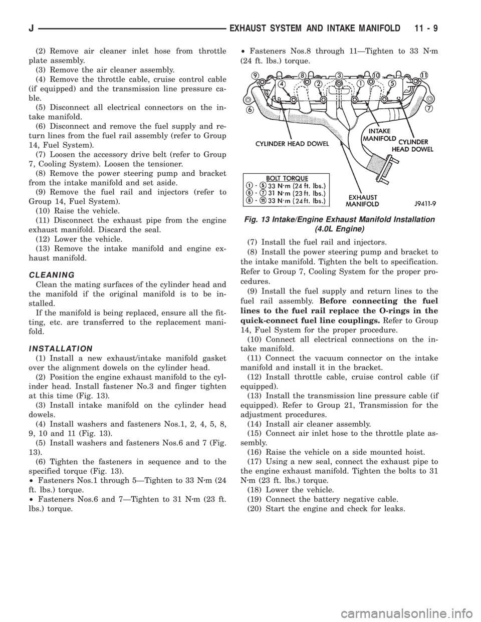
at this time (Fig. 13).
(3) Install intake manifold on the cylinder head
dowels.
(4) Install washers and fasteners Nos.1, 2, 4, 5, 8,
9, 10 and 11 (Fig. 13).
(5) Install washers and fasteners Nos.6 and 7 (Fig.
13).
(6) Tighten the fasteners in sequence and to the
specified torque (Fig. 13).
²Fasteners Nos.1 through 5ÐTighten to 33 Nzm (24
ft. lbs.) torque.
²Fasteners Nos.6 and 7ÐTighten to 31 Nzm (23 ft.
lbs.) torque.²Fasteners Nos.8 through 11ÐTighten to 33 Nzm
(24 ft. lbs.) torque.
(7) Install the fuel rail and injectors.
(8) Install the power steering pump and bracket to
the intake manifold. Tighten the belt to specification.
Refer to Group 7, Cooling System for the proper pro-
cedures.
(9) Install the fuel supply and return lines to the
fuel rail assembly.Before connecting the fuel
lines to the fuel rail replace the O-rings in the
quick-connect fuel line couplings.Refer to Group
14, Fuel System for the proper procedure.
(10) Connect all electrical connections on the in-
take manifold.
(11) Connect the vacuum connector on the intake
manifold and install it in the bracket.
(12) Install throttle cable, cruise control cable (if
equipped).
(13) Install the transmission line pressure cable (if
equipped). Refer to Group 21, Transmission for the
adjustment procedures.
(14) Install air cleaner assembly.
(15) Connect air inlet hose to the throttle plate as-
sembly.
(16) Raise the vehicle on a side mounted hoist.
(17) Using a new seal, connect the exhaust pipe to
the engine exhaust manifold. Tighten the bolts to 31
Nzm (23 ft. lbs.) torque.
(18) Lower the vehicle.
(19) Connect the battery negative cable.
(20) Start the engine and check for leaks.
Fig. 13 Intake/Engine Exhaust Manifold Installation
(4.0L Engine)
JEXHAUST SYSTEM AND INTAKE MANIFOLD 11 - 9
Page 1415 of 2158
FUEL TANKS
INDEX
page page
Fuel Gauge Sending Unit................... 16
Fuel Tank............................... 13
Fuel Tank Capacities....................... 13
Fuel Tank Filler Tube Cap................... 13Fuel Tank Pressure Relief/Rollover Valve........ 16
General Information....................... 13
Heat Shields............................. 13
No-Lead Fuel Tank Filler Tube................ 13
GENERAL INFORMATION
All XJ and YJ models pass a full 360 degree roll-
over test without fuel leakage. To accomplish this,
fuel and vapor flow controls are required for all fuel
tank connections.
All models are equipped with a pressure relief/roll-
over valve mounted in the top of the fuel tank. The
return line from the fuel pump to the fuel tank con-
tains a one-way check valve.
An evaporative control system prevents raw fuel
vapor from escaping into the atmosphere. Fuel va-
pors from the fuel tank are collected in the EVAP
canister. When the engine is operating, the vapors
are drawn into the intake manifold to be used in
combustion. Refer to Group 25, Emission Control
System for more information.
Inspect all hose/tube connections for completeness.
Be sure that leaks are not present. Replace any hose
that is cracked, scuffed, swelled, has rubbed against
other vehicle components or shows any other sign of
wear that could lead to failure. If it is necessary to
replace a hose, only hose marked EFM/EFI may be
used.
When installing hoses, be sure that they are routed
away from contact with other vehicle components.
The hose clamps used on fuel injected vehicles are
of a special rolled edge construction to prevent the
edge of the clamp from cutting into the hose. Only
these rolled edge type clamps may be used on this
system. Other types of clamps may cut into the hoses
and cause high-pressure fuel leaks.
FUEL TANK CAPACITIES
Refer to the Specifications section at the end of this
group.
NO-LEAD FUEL TANK FILLER TUBE
All vehicles are designed to operate using Unleaded
fuels. The diameter of the opening in the fuel tank
filler neck is sized to only accept unleaded fuel noz-
zles. Gasoline station pumps for unleaded and leaded
fuels have different size nozzles. Leaded fuel nozzles
are larger in diameter than unleaded nozzles. The
fuel tank filler neck opening is also equipped with adeflector, which the smaller unleaded nozzle pushes
back upon entering the filler neck. The deflector will
prevent the larger diameter leaded fuel nozzles from
entering the filler neck and will deflect fuel away
from the filler neck. This happens if filling of the
tank with leaded fuel is attempted.
A label is attached to the instrument panel under
the fuel gauge that reads UNLEADED FUEL ONLY
as a reminder to the driver. A similar label is located
near the fuel tank filler.
FUEL TANK FILLER TUBE CAP
The loss of any fuel or vapor out of the filler neck
is prevented by the use of a safety filler cap. This
will release only under pressure of 10.9 to 13.45 kPa
(1.58 to 1.95 psi). The vacuum release is between .97
and 2.0 kPa (.14 and .29 psi). This cap must be re-
placed by a similar unit if replacement is necessary.
CAUTION: Remove the fuel tank filler tube cap prior
to removing or repairing fuel lines to relieve fuel
tank pressure.
HEAT SHIELDS
The sheet metal heat shields may have to be re-
moved when servicing the fuel tank, fuel lines or va-
por vent line. The heat shields must be installed to
protect the lines and tank from the heat of the ex-
haust system. Refer to Group 11, Exhaust System
and Intake Manifold for proper installation.
FUEL TANK
WARNING: THE FUEL SYSTEM IS UNDER CON-
STANT FUEL PRESSURE (EVEN WITH THE ENGINE
OFF) OF APPROXIMATELY 131-269 KPA (19-39 PSI).
THIS PRESSURE MUST BE RELEASED BEFORE
SERVICING FUEL TANK.
REMOVALÐXJ MODELS
Perform the preceding Fuel System Pressure Re-
lease Procedure.
(1) Disconnect negative battery cable.
JFUEL TANKS 14 - 13
Page 1536 of 2158
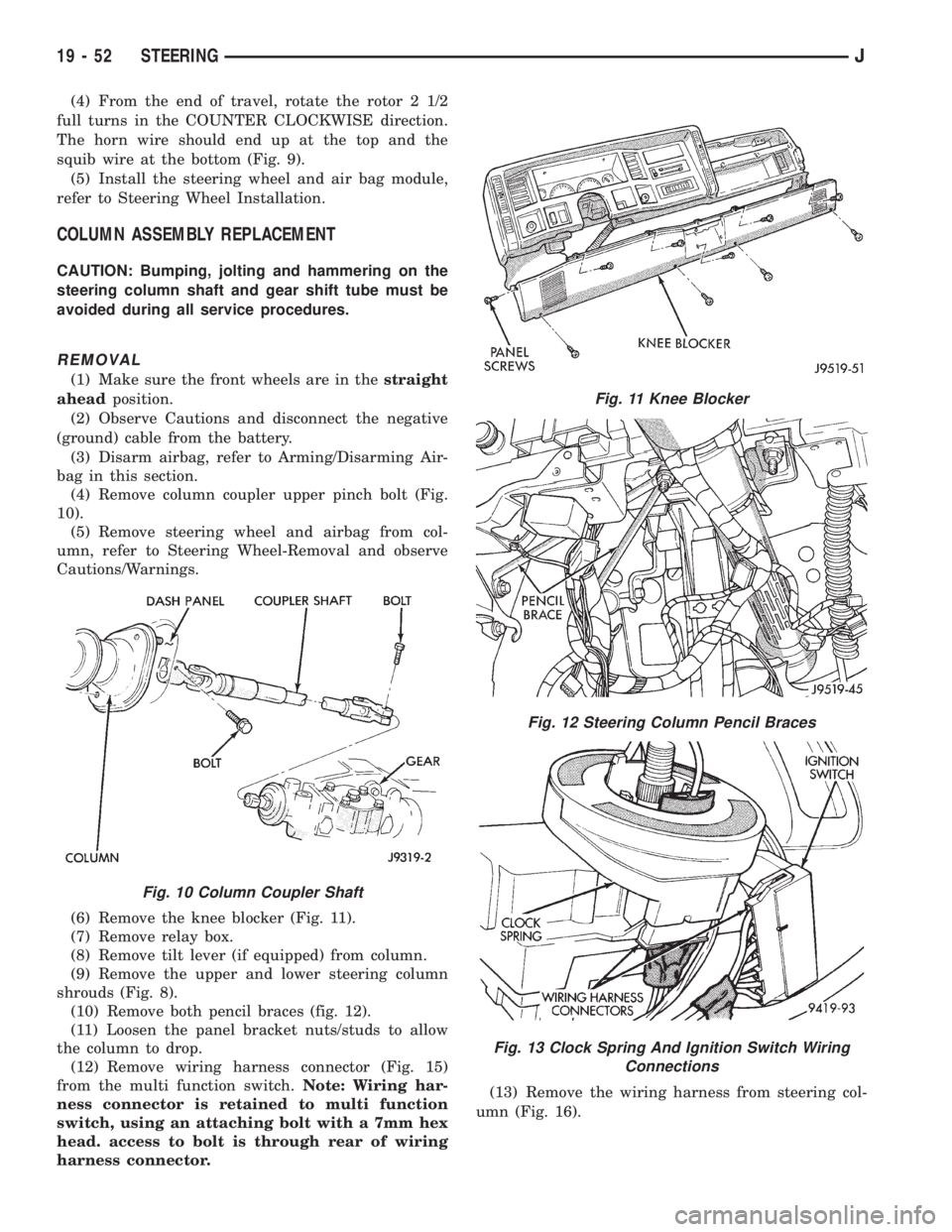
(4) From the end of travel, rotate the rotor 2 1/2
full turns in the COUNTER CLOCKWISE direction.
The horn wire should end up at the top and the
squib wire at the bottom (Fig. 9).
(5) Install the steering wheel and air bag module,
refer to Steering Wheel Installation.
COLUMN ASSEMBLY REPLACEMENT
CAUTION: Bumping, jolting and hammering on the
steering column shaft and gear shift tube must be
avoided during all service procedures.
REMOVAL
(1) Make sure the front wheels are in thestraight
aheadposition.
(2) Observe Cautions and disconnect the negative
(ground) cable from the battery.
(3) Disarm airbag, refer to Arming/Disarming Air-
bag in this section.
(4) Remove column coupler upper pinch bolt (Fig.
10).
(5) Remove steering wheel and airbag from col-
umn, refer to Steering Wheel-Removal and observe
Cautions/Warnings.
(6) Remove the knee blocker (Fig. 11).
(7) Remove relay box.
(8) Remove tilt lever (if equipped) from column.
(9) Remove the upper and lower steering column
shrouds (Fig. 8).
(10) Remove both pencil braces (fig. 12).
(11) Loosen the panel bracket nuts/studs to allow
the column to drop.
(12) Remove wiring harness connector (Fig. 15)
from the multi function switch.Note: Wiring har-
ness connector is retained to multi function
switch, using an attaching bolt with a 7mm hex
head. access to bolt is through rear of wiring
harness connector.(13) Remove the wiring harness from steering col-
umn (Fig. 16).
Fig. 10 Column Coupler Shaft
Fig. 11 Knee Blocker
Fig. 12 Steering Column Pencil Braces
Fig. 13 Clock Spring And Ignition Switch Wiring
Connections
19 - 52 STEERINGJ
Page 1542 of 2158
STEERING COLUMNÐYJ
INDEX
page page
Assembly............................... 63
Assembly............................... 71
Column Replacement...................... 58
Disassembly............................. 66DisassemblyÐColumn or Console Shift......... 60
Non-Tilt Steering Column................... 60
Steering Wheel........................... 58
Tilt Steering Column....................... 66
The column may be disassembled and reassembled.
Also most steering column components can be serviced
without removing the column from the vehicle. For ad-
ditional information, refer to Group 8H, Electrical.
CAUTION: Bumping, jolting and hammering on the
steering column shaft and gear shift tube must be
avoided during all service procedures.
CAUTION: Disconnect negative (ground) cable from the
battery before servicing any component on the column.
Safety goggles should be worn at all times
when involved with steering column service.
STEERING WHEEL
REMOVAL
(1) Make sure the front wheels are in thestraight
aheadposition.
(2) Disconnect the negative (ground) cable from the
battery.
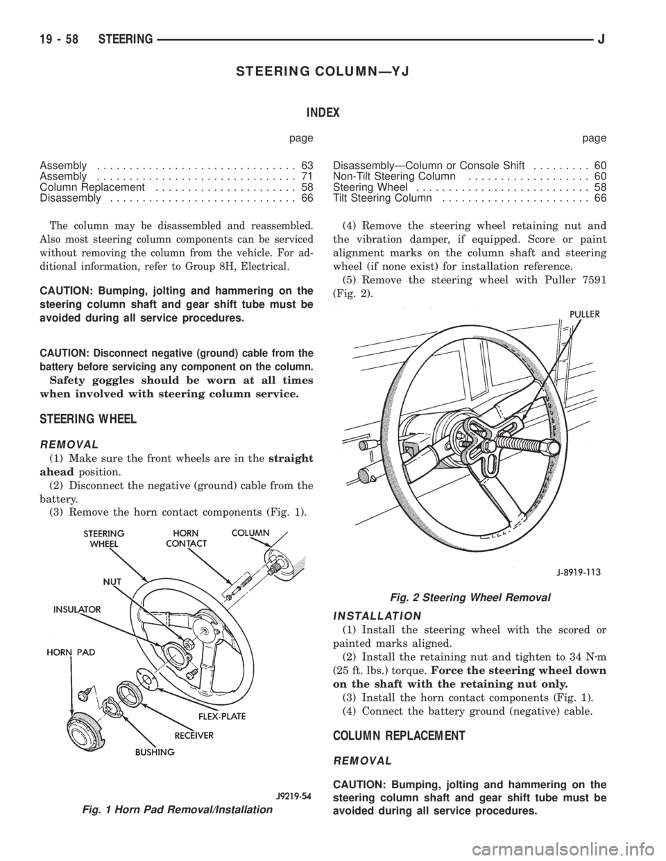
(3) Remove the horn contact components (Fig. 1).(4) Remove the steering wheel retaining nut and
the vibration damper, if equipped. Score or paint
alignment marks on the column shaft and steering
wheel (if none exist) for installation reference.
(5) Remove the steering wheel with Puller 7591
(Fig. 2).
INSTALLATION
(1) Install the steering wheel with the scored or
painted marks aligned.
(2) Install the retaining nut and tighten to 34 Nzm
(25 ft. lbs.) torque.Force the steering wheel down
on the shaft with the retaining nut only.
(3) Install the horn contact components (Fig. 1).
(4) Connect the battery ground (negative) cable.
COLUMN REPLACEMENT
REMOVAL
CAUTION: Bumping, jolting and hammering on the
steering column shaft and gear shift tube must be
avoided during all service procedures.
Fig. 1 Horn Pad Removal/Installation
Fig. 2 Steering Wheel Removal
19 - 58 STEERINGJ
Page 1549 of 2158
(6) Position the turn signal switch and wire har-
ness in the cylinder housing. Fold the wires against
the connector. Route the connector down through the
steering column jacket.
(7) Install the windshield wiper wire harness and
switch. Route the wire harness down through steer-
ing column jacket.
(8) Align the turn signal switch in the housing and
secure the switch with the attaching screws. Tighten
the screws to 4 Nzm (35 in. lbs.) torque.
(9) Install the dimmer switch actuator arm.
Tighten the attaching screws to 4 Nzm (35 in. lbs.)
torque.
(10) If equipped, install the cruise control wire har-
ness. Install the turn signal stalk by pushing it
straight into the column.
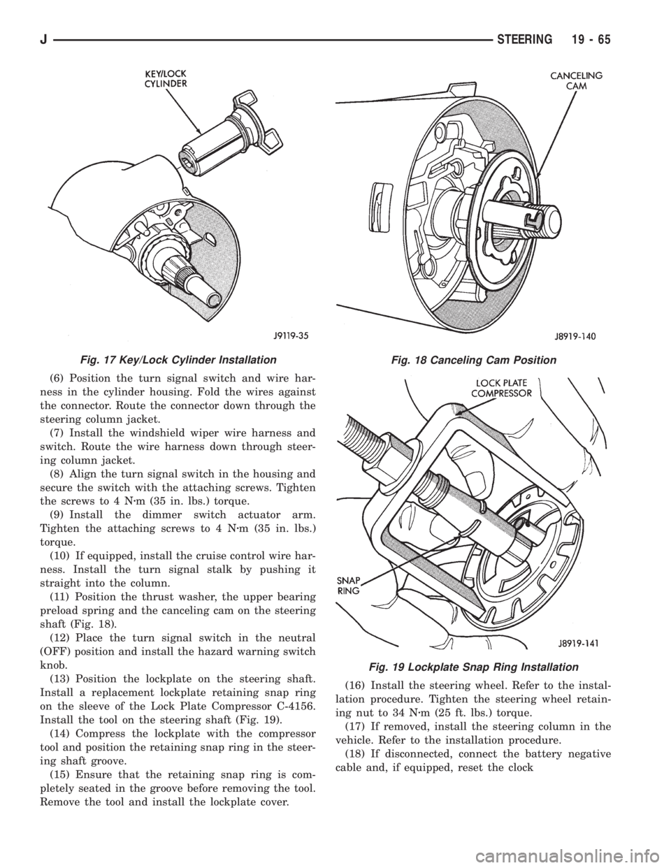
(11) Position the thrust washer, the upper bearing
preload spring and the canceling cam on the steering
shaft (Fig. 18).
(12) Place the turn signal switch in the neutral
(OFF) position and install the hazard warning switch
knob.
(13) Position the lockplate on the steering shaft.
Install a replacement lockplate retaining snap ring
on the sleeve of the Lock Plate Compressor C-4156.
Install the tool on the steering shaft (Fig. 19).
(14) Compress the lockplate with the compressor
tool and position the retaining snap ring in the steer-
ing shaft groove.
(15) Ensure that the retaining snap ring is com-
pletely seated in the groove before removing the tool.
Remove the tool and install the lockplate cover.(16) Install the steering wheel. Refer to the instal-
lation procedure. Tighten the steering wheel retain-
ing nut to 34 Nzm (25 ft. lbs.) torque.
(17) If removed, install the steering column in the
vehicle. Refer to the installation procedure.
(18) If disconnected, connect the battery negative
cable and, if equipped, reset the clock
Fig. 17 Key/Lock Cylinder InstallationFig. 18 Canceling Cam Position
Fig. 19 Lockplate Snap Ring Installation
JSTEERING 19 - 65