1995 JEEP YJ run flat
[x] Cancel search: run flatPage 204 of 2158

(4) Install new spring nuts on wheel studs.
(5) Install wheel and lower vehicle.
DISC BRAKE ROTOR THICKNESS
Rotor minimum usable thickness is 22.7 mm (0.89
in.). This dimension is either cast, or stamped on the
rotor hub, or outer edge.
Measure rotor thickness at the center of the brake-
shoe contact surface.
Replace the rotor if worn below minimum thick-
ness. Also replace the rotor if refinishing would re-
duce thickness below the allowable minimum.
DISC BRAKE ROTOR RUNOUT
Check rotor lateral runout whenever pedal pulsa-
tion, or rapid, uneven brakelining wear has occurred.
On 4-wheel drive models, the rotor must be se-
curely clamped to the hub to ensure an accurate
runout measurement. Secure the rotor with the
wheel nuts and 4 or 5 large diameter flat washers on
each stud as shown (Fig. 27).
Use a dial indicator to check lateral runout (Fig.
27).
Maximum allowable rotor lateral runout is 0.13
mm (0.005 in.).
Check lateral runout with a dial indicator (Fig. 28).
Excessive lateral runout will cause brake pedal pul-
sation and rapid, uneven wear of the brakeshoes.
Maximum allowable rotor runout for all models is
0.12 mm (0.005 in.).
DISC BRAKE ROTOR THICKNESS VARIATION
Variations in rotor thickness will cause pedal pul-
sation, noise and shudder.
Measure rotor thickness at four to six points
around the rotor face. Position the micrometer ap-
proximately 2 cm (3/4 in.) from the rotor outer cir-
cumference for each measurement (Fig. 29).
Thickness should notvaryby more than 0.013 mm
(0.0005 in.) from point-to-point on the rotor. Refinish
or replace the rotor if necessary.
Fig. 26 Rotor And HubFig. 27 Securing4x4Rotor For Lateral Runout Check
Fig. 28 Typical Method Of Checking Rotor Lateral
Runout
Fig. 29 Measuring Rotor Thickness Variation
5 - 52 DISC BRAKESJ
Page 466 of 2158

SERVICE PROCEDURES
INDEX
page page
Back-Up/Rear Turn Signal/Tail Lamp Bulb
ReplacementÐXJ....................... 12
Center High Mounted Stop Lamp (CHMSL)ÐXJ . . 12
Daytime Running Lights (Canada Only)ÐXJ..... 15
Drl Module ReplacementÐXJ................ 15
Fog Lamp ReplacementÐXJ.................. 9
Fog Lamp Switch ReplacementÐXJ........... 10
Fog LampsÐXJ........................... 7
Front Park/Turn Signal Lamp Bulb
ReplacementÐXJ........................ 9
Headlamp Alignment PreparationÐXJ........... 6
Headlamp AlignmentÐXJ.................... 6
Headlamp Bulb ReplacementÐXJ.............. 7Headlamp Delay Function Trouble DiagnosisÐXJ . 14
Headlamp Delay Module ReplacementÐXJ...... 14
Headlamp SwitchÐXJ...................... 10
Headlamp/Fog Lamp Adjustment Using Alignment
ScreenÐXJ............................. 7
License Plate LampÐXJ.................... 12
Multi-Function Switch Service ProceduresÐXJ.... 11
Sentinel Headlamp Delay ModuleÐXJ.......... 14
Side Marker Lamp Bulb ReplacementÐXJ....... 10
Underhood Lamp Bulb ReplacementÐXJ....... 13
Underhood Lamp ReplacementÐXJ........... 13
Underhood Lamp Service InformationÐXJ....... 12
HEADLAMP ALIGNMENTÐXJ
Headlamps can be aligned using the screen method
provided in this section. Alignment Tool C4466-A or
equivalent can also be used. Refer to instructions
provided with the tool for proper procedures.The
preferred headlamp alignment setting is 0 for
the left/right adjustment and 1(down for the
up/down adjustment.
HEADLAMP ALIGNMENT PREPARATIONÐXJ
(1) Verify headlamp dimmer switch and high beam
indicator operation.
(2) Correct defective components that could hinder
proper headlamp alignment.
(3) Verify proper tire inflation.
(4) Clean headlamp lenses.
(5) Verify that luggage area is not heavily loaded.
Fig. 1 Headlamp Alignment ScreenÐTypical
8L - 6 LAMPSÐXJ VEHICLESJ
Page 482 of 2158

SERVICE PROCEDURES
INDEX
page page
Back-Up/Rear Turn Signal/Tail Lamp Bulb
ReplacementÐYJ....................... 28
Center High Mounted Stop Lamp (CHMSL)ÐYJ . . 28
Daytime Running Lights (Canada Only)ÐYJ..... 30
Drl Module ReplacementÐYJ................ 30
Fog Lamp ReplacementÐYJ................. 25
Fog Lamp Switch ReplacementÐYJ........... 26
Fog LampsÐYJ.......................... 23
Front Park/Turn Signal Lamp Bulb ReplacementÐ
YJ ................................... 25
Headlamp Alignment PreparationÐYJ.......... 22Headlamp AlignmentÐYJ................... 22
Headlamp Bulb ReplacementÐYJ............. 23
Headlamp Dimmer Switch ReplacementÐYJ..... 26
Headlamp SwitchÐYJ...................... 26
Headlamp/Fog Lamp Adjustment Using Alignment
ScreenÐYJ............................ 23
Side Marker Lamp Bulb ReplacementÐYJ....... 25
Underhood Lamp Bulb ReplacementÐYJ....... 29
Underhood Lamp ReplacementÐYJ........... 29
Underhood Lamp Service InformationÐYJ....... 28
HEADLAMP ALIGNMENTÐYJ
Headlamps can be aligned using the screen method
provided in this section. Alignment Tool C4466-A or
equivalent can also be used. Refer to instructions
provided with the tool for proper procedures.The
preferred headlamp alignment setting is 0 for
the left/right adjustment and 1(down for the
up/down adjustment.
HEADLAMP ALIGNMENT PREPARATIONÐYJ
(1) Verify headlamp dimmer switch and high beam
indicator operation.
(2) Correct defective components that could hinder
proper headlamp alignment.
(3) Verify proper tire inflation.
(4) Clean headlamp lenses.
(5) Verify that luggage area is not heavily loaded.
(6) Fuel tank should be FULL. Add 2.94 kg (6.5
lbs.) of weight over the fuel tank for each estimated
gallon of missing fuel.
Fig. 1 Headlamp Alignment ScreenÐTypical
8L - 22 LAMPSÐYJ VEHICLESJ
Page 1910 of 2158
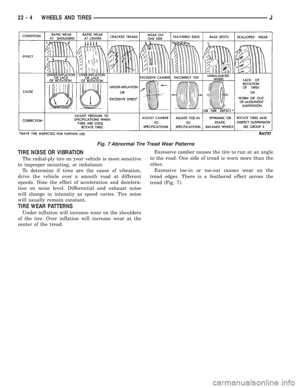
TIRE NOISE OR VIBRATION
The radial-ply tire on your vehicle is more sensitive
to improper mounting, or imbalance.
To determine if tires are the cause of vibration,
drive the vehicle over a smooth road at different
speeds. Note the effect of acceleration and decelera-
tion on noise level. Differential and exhaust noise
will change in intensity as speed varies. Tire noise
will usually remain constant.
TIRE WEAR PATTERNS
Under inflation will increase wear on the shoulders
of the tire. Over inflation will increase wear at the
center of the tread.Excessive camber causes the tire to run at an angle
to the road. One side of tread is worn more than the
other.
Excessive toe-in or toe-out causes wear on the
tread edges. There is a feathered effect across the
tread (Fig. 7).
Fig. 7 Abnormal Tire Tread Wear Patterns
22 - 4 WHEELS AND TIRESJ
Page 1912 of 2158
WHEELS
GENERAL INFORMATION
Original equipment wheels are designed for the
specified Maximum Vehicle Capacity.
All models use steel or cast aluminum drop center
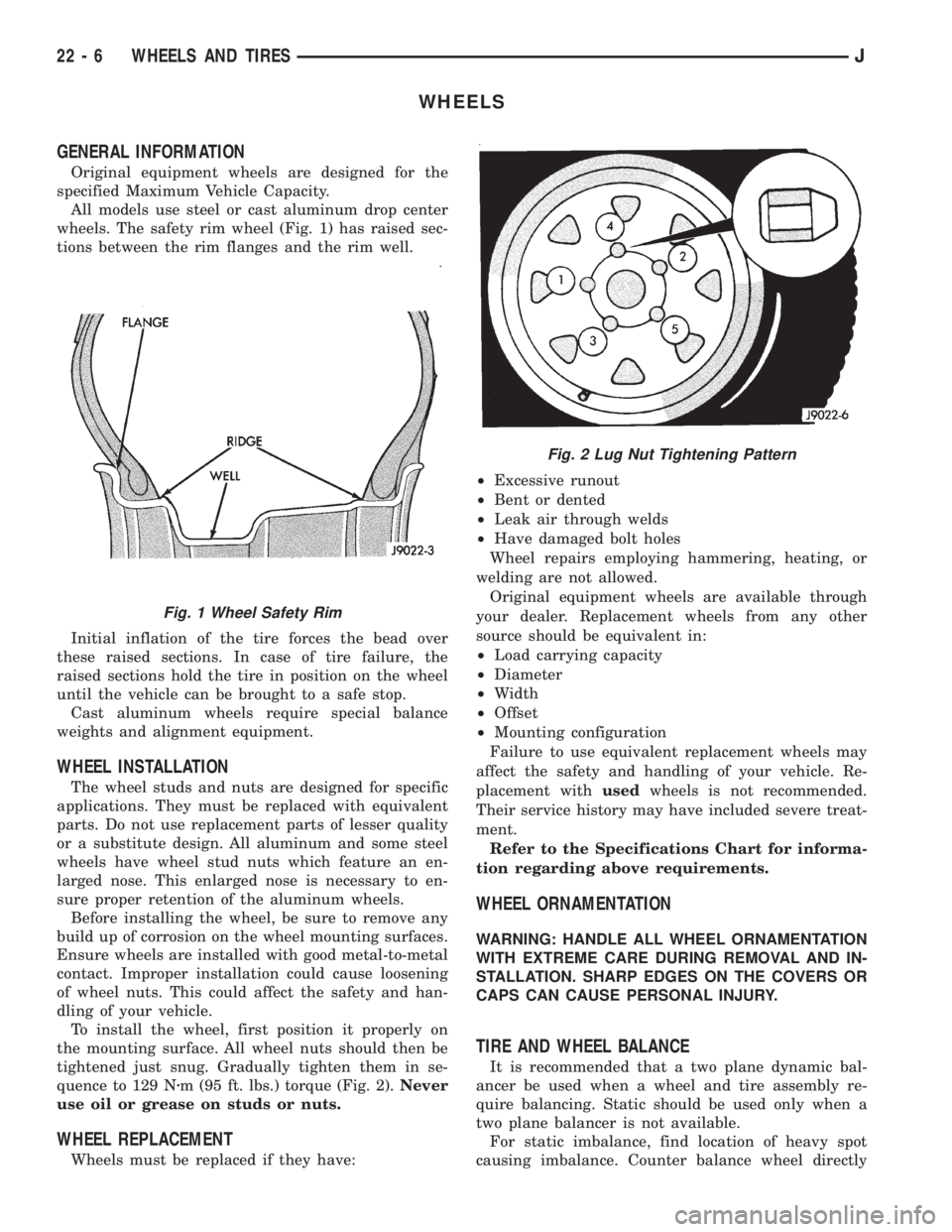
wheels. The safety rim wheel (Fig. 1) has raised sec-
tions between the rim flanges and the rim well.
Initial inflation of the tire forces the bead over
these raised sections. In case of tire failure, the
raised sections hold the tire in position on the wheel
until the vehicle can be brought to a safe stop.
Cast aluminum wheels require special balance
weights and alignment equipment.
WHEEL INSTALLATION
The wheel studs and nuts are designed for specific
applications. They must be replaced with equivalent
parts. Do not use replacement parts of lesser quality
or a substitute design. All aluminum and some steel
wheels have wheel stud nuts which feature an en-
larged nose. This enlarged nose is necessary to en-
sure proper retention of the aluminum wheels.
Before installing the wheel, be sure to remove any
build up of corrosion on the wheel mounting surfaces.
Ensure wheels are installed with good metal-to-metal
contact. Improper installation could cause loosening
of wheel nuts. This could affect the safety and han-
dling of your vehicle.
To install the wheel, first position it properly on
the mounting surface. All wheel nuts should then be
tightened just snug. Gradually tighten them in se-
quence to 129 Nzm (95 ft. lbs.) torque (Fig. 2).Never
use oil or grease on studs or nuts.
WHEEL REPLACEMENT
Wheels must be replaced if they have:²Excessive runout
²Bent or dented
²Leak air through welds
²Have damaged bolt holes
Wheel repairs employing hammering, heating, or
welding are not allowed.
Original equipment wheels are available through
your dealer. Replacement wheels from any other
source should be equivalent in:
²Load carrying capacity
²Diameter
²Width
²Offset
²Mounting configuration
Failure to use equivalent replacement wheels may
affect the safety and handling of your vehicle. Re-
placement withusedwheels is not recommended.
Their service history may have included severe treat-
ment.
Refer to the Specifications Chart for informa-
tion regarding above requirements.
WHEEL ORNAMENTATION
WARNING: HANDLE ALL WHEEL ORNAMENTATION
WITH EXTREME CARE DURING REMOVAL AND IN-
STALLATION. SHARP EDGES ON THE COVERS OR
CAPS CAN CAUSE PERSONAL INJURY.
TIRE AND WHEEL BALANCE
It is recommended that a two plane dynamic bal-
ancer be used when a wheel and tire assembly re-
quire balancing. Static should be used only when a
two plane balancer is not available.
For static imbalance, find location of heavy spot
causing imbalance. Counter balance wheel directly
Fig. 1 Wheel Safety Rim
Fig. 2 Lug Nut Tightening Pattern
22 - 6 WHEELS AND TIRESJ
Page 1915 of 2158
Drive vehicle a short distance to eliminate tire flat
spotting from a parked position.
Make sure all wheel nuts are properly torqued.
Relocate wheel on the mounting, two studs over
from the original position.
Re-tighten wheel nuts until all are properly
torqued, to eliminate brake distortion.
Check radial runout. If still excessive, mark tire
sidewall, wheel, and stud at point of maximum
runout and proceed to Method 2.
METHOD 2 (RELOCATE TIRE ON WHEEL)
Rotating tire on wheel is particularly effective
when there is runout in both tire and wheel.Remove tire from wheel and re-mount wheel on
hub in former position.
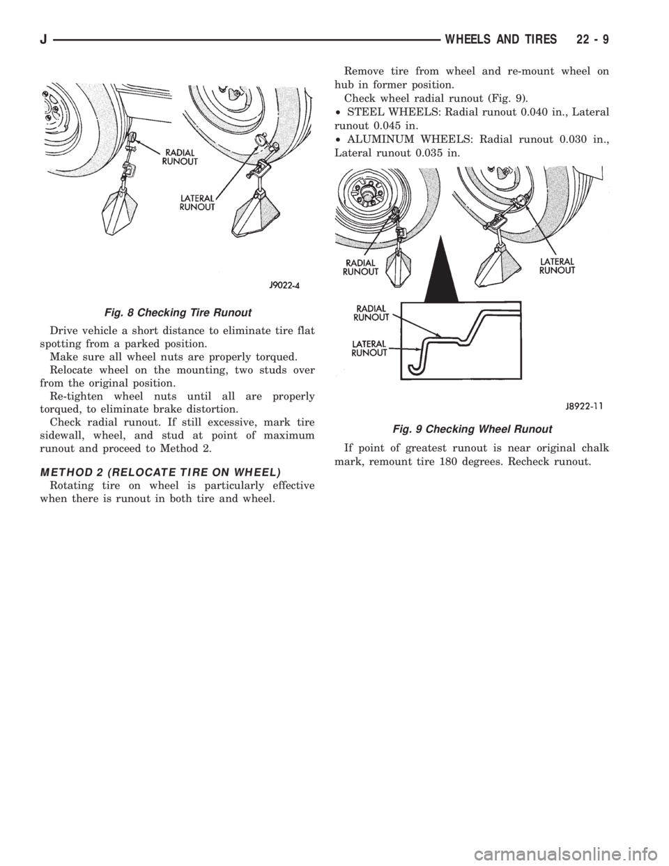
Check wheel radial runout (Fig. 9).
²STEEL WHEELS: Radial runout 0.040 in., Lateral
runout 0.045 in.
²ALUMINUM WHEELS: Radial runout 0.030 in.,
Lateral runout 0.035 in.
If point of greatest runout is near original chalk
mark, remount tire 180 degrees. Recheck runout.
Fig. 8 Checking Tire Runout
Fig. 9 Checking Wheel Runout
JWHEELS AND TIRES 22 - 9
Page 1916 of 2158
VEHICLE VIBRATION
Vehicle vibration can be caused by:
²Tire/wheel unbalance or excessive runout
²Defective tires with extreme tread wear
²Nylon overlay flat spots (performance tires only)
²Incorrect wheel bearing adjustment (if applicable)
²Loose or worn suspension/steering components
²Certain tire tread patterns
²Incorrect drive shaft angles or excessive drive
shaft/yoke runout
²Defective or worn U-joints
²Excessive brake rotor or drum runout
²Loose engine or transmission supports/mounts
²And by engine operated accessories
Refer to the appropriate Groups in this man-
ual for additional information.
VIBRATION TYPES
There are two types of vehicle vibration:
²Mechanical
²Audible.
Mechanical vehicle vibration can be felt through
the seats, floor pan and/or steering wheel.
Audible vehicle vibration is heard above normal
background noise. The sound can be a droning or
drumming noise.
Vibrations are sensitive to change in engine torque,
vehicle speed or engine speed.
ENGINE TORQUE SENSITIVE VIBRATION
This vibration can be increased or decreased by:
²Accelerating
²Decelerating
²Coasting
²Maintaining a constant vehicle speed
VEHICLE SPEED SENSITIVE VIBRATION
This vibration condition always occurs at the same
vehicle speed regardless of the engine torque or en-
gine speed.
ENGINE SPEED (RPM) SENSITIVE VIBRATION
This vibration occurs at varying engine speeds. It
can be isolated by increasing or decreasing the en-
gine speed with the transmission in NEUTRAL posi-
tion.
VIBRATION DIAGNOSIS
A vibration diagnosis should always begin with a
10 mile (16 km) trip (to warm the vehicle and tires).
Then a road test to identify the vibration. Corrective
action should not be attempted until the vibration
type has been identified via a road test.
During the road test, drive the vehicle on a smooth
surface. If vibration exists, note and record the fol-
lowing information:²Identify the vehicle speed range when the vibra-
tion occurs
²Identify the type of vibration
²Identify the vibration sensitivity
²Determine if the vibration is affected by changes
in vehicle speed, engine speed and engine torque.
When the vibration has been identified, refer to the
Vibration Diagnosis chart for causes. Consider cor-
recting only those causes coded in the chart that are
related to the vibration condition.
Refer to the following cause codes and descriptions
for explanations when referring to the chart.
TRRÐTire and Wheel Radial Runout:Vehicle
speed sensitive, mechanical vibration. The runout
will not cause vibration below 20 mph (32 km/h).
WHÐWheel Hop:Vehicle speed sensitive, me-
chanical vibration. The wheel hop generates rapid
up-down movement in the steering wheel. The vibra-
tion is most noticeable in the 20 - 40 mph (32 - 64
km/h) range. The wheel hop will not cause vibration
below 20 mph (32 km/h). Wheel hop is caused by a
tire/wheel that has a radial runout of more than
0.045 of-an-inch (1.14 mm). If wheel runout is accept-
able and combined runout cannot be reduced by re-
positioning the tire on wheel, replace tire.
TBÐTire/Wheel Balance:Vehicle speed sensitive,
mechanical vibration. Static tire/wheel unbalance
will not cause vibration below 30 mph (46 km/h). Dy-
namic tire/wheel unbalance will not cause vibration
below 40 mph (64 km/h).
TLRÐTire/Wheel Lateral runout:Vehicle speed
sensitive, mechanical vibration. The runout will not
cause vibration below 50 - 55 mph (80 - 88 km/h). Ex-
cessive lateral runout will also cause front-end
shimmy.
TWÐTire Wear:Vehicle speed sensitive, audible
vibration. Abnormal tire wear causes small vibration
in the 30 - 55 mph (88 km/h) range. This will pro-
duce a whine noise at high speed. The whine will
change to a growl noise when the speed is reduced.
WÐTire Waddle:Vehicle speed sensitive, mechan-
ical vibration. Irregular tire uniformity can cause
side-to-side motion during speeds up to 15 mph (24
km/h). If the motion is excessive, identify the defec-
tive tire and replace it.
UAJÐUniversal Joint (Drive Shaft) Angles:
Torque/vehicle speed sensitive, mechanical/audible vi-
bration. Incorrect drive shaft angles cause mechani-
cal vibration below 20 mph (32 km/h) and in the 70
mph (112 km/h) range. The incorrect angles can also
produce an audible vibration in the 20 - 50 mph (32 -
80 km/h) range. Caster adjustment could be required
to correct the angles.
UJÐUniversal Joints:Engine torque/vehicle
speed sensitive, mechanical/audible vibration. If the
22 - 10 WHEELS AND TIRESJ
Page 2138 of 2158
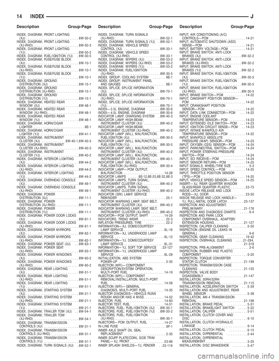
INDEX, DIAGRAM; FRONT LIGHTING
(XJ).............................8W-50-2
INDEX, DIAGRAM; FRONT LIGHTING
(XJ-RHD).........................8W-50-3
INDEX, DIAGRAM; FRONT LIGHTING
(YJ).............................8W-50-2
INDEX, DIAGRAM; FUEL/IGNITION (YJ) . 8W-30-5
INDEX, DIAGRAM; FUSE/FUSE BLOCK
(XJ).............................8W-10-1
INDEX, DIAGRAM; FUSE/FUSE BLOCK
(XJ-RHD).........................8W-10-1
INDEX, DIAGRAM; FUSE/FUSE BLOCK
(YJ).............................8W-10-1
INDEX, DIAGRAM; GROUND
DISTRIBUTION (XJ)................8W-15-1
INDEX, DIAGRAM; GROUND
DISTRIBUTION (XJ-RHD)............8W-15-1
INDEX, DIAGRAM; GROUND
DISTRIBUTION (YJ)................8W-15-1
INDEX, DIAGRAM; HEATED REAR
WINDOW (XJ).....................8W-48-1
INDEX, DIAGRAM; HEATED REAR
WINDOW (XJ-RHD).................8W-48-1
INDEX, DIAGRAM; HEATED REAR
WINDOW (YJ).....................8W-48-1
INDEX, DIAGRAM; HORN/CIGAR
LIGHTER............................8E-1
INDEX, DIAGRAM; HORN/CIGAR
LIGHTER (YJ).....................8W-41-1
INDEX, DIAGRAM; INSTRUMENT
CLUSTER (XJ).............8W-40-1,8W-40-3
INDEX, DIAGRAM; INSTRUMENT
CLUSTER (XJ-RHD)................8W-40-3
INDEX, DIAGRAM; INSTRUMENT
CLUSTER (YJ).....................8W-40-2
INDEX, DIAGRAM; INTERIOR LIGHTING
(XJ).............................8W-44-2
INDEX, DIAGRAM; INTERIOR LIGHTING
(XJ-RHD).........................8W-44-2
INDEX, DIAGRAM; INTERIOR LIGHTING
(YJ).............................8W-44-2
INDEX, DIAGRAM; OVERHEAD CONSOLE
(XJ).............................8W-49-1
INDEX, DIAGRAM; OVERHEAD CONSOLE
(XJ-RHD).........................8W-49-1
INDEX, DIAGRAM; POWER
DISTRIBUTION (XJ)................8W-11-1
INDEX, DIAGRAM; POWER
DISTRIBUTION (XJ-RHD)............8W-11-1
INDEX, DIAGRAM; POWER
DISTRIBUTION (YJ)................8W-11-1
INDEX, DIAGRAM; POWER DOOR LOCKS
(XJ).............................8W-61-1
INDEX, DIAGRAM; POWER DOOR LOCKS
(XJ-RHD).........................8W-61-1
INDEX, DIAGRAM; POWER MIRRORS
(XJ).............................8W-62-1
INDEX, DIAGRAM; POWER MIRRORS
(XJ-RHD).........................8W-62-1
INDEX, DIAGRAM; POWER SEAT (XJ) . . 8W-63-1
INDEX, DIAGRAM; POWER SEAT
(XJ-RHD).........................8W-63-1
INDEX, DIAGRAM; POWER WINDOWS
(XJ).............................8W-60-2
INDEX, DIAGRAM; POWER WINDOWS
(XJ-RHD).........................8W-60-2
INDEX, DIAGRAM; REAR LIGHTING
(XJ).............................8W-51-1
INDEX, DIAGRAM; REAR LIGHTING
(XJ-RHD).........................8W-51-1
INDEX, DIAGRAM; REAR LIGHTING
(YJ).............................8W-51-1
INDEX, DIAGRAM; STARTING SYSTEM
(XJ).............................8W-21-1
INDEX, DIAGRAM; STARTING SYSTEM
(XJ-RHD).........................8W-21-1
INDEX, DIAGRAM; STARTING SYSTEM
(YJ).............................8W-21-1
INDEX, DIAGRAM; TRAILER TOW (XJ) . . 8W-54-1
INDEX, DIAGRAM; TRAILER TOW
(XJ-RHD)
.........................8W-54-1
INDEX, DIAGRAM; TRANSMISSION
CONTROLS (XJ)
...................8W-31-1
INDEX, DIAGRAM; TRANSMISSION
CONTROLS (XJ-RHD)
...............8W-31-1
INDEX, DIAGRAM; TRANSMISSION
CONTROLS (YJ)
...................8W-31-1
INDEX, DIAGRAM; TURN SIGNALS (XJ)
. 8W-52-1INDEX, DIAGRAM; TURN SIGNALS
(XJ-RHD).........................8W-52-1
INDEX, DIAGRAM; TURN SIGNALS (YJ) . 8W-52-1
INDEX, DIAGRAM; VEHICLE SPEED
CONTROL (XJ)....................8W-33-1
INDEX, DIAGRAM; VEHICLE SPEED
CONTROL (XJ-RHD)................8W-33-1
INDEX, DIAGRAM; WIPERS (XJ).......8W-53-2
INDEX, DIAGRAM; WIPERS (XJ-RHD) . . 8W-53-2
INDEX, DIAGRAM; WIPERS (YJ).......8W-53-2
INDEX, DIAGRAM; FUEL/IGNITION
(XJ-RHD).........................8W-30-5
INDEX, GROUP; COOLING SYSTEM.......8E-1
INDEX, GROUP; INSTRUMENT PANEL
AND GAUGES........................8E-1
INDEX, SPLICE; SPLICE INFORMATION
(XJ).............................8W-70-1
INDEX, SPLICE; SPLICE INFORMATION
(XJ-RHD).........................8W-70-1
INDEX, SPLICE; SPLICE INFORMATION
(YJ).............................8W-70-1
INDEXÐ2.5L ENGINE, DIAGRAM......8W-30-6
INDEXÐ4.0L ENGINE, DIAGRAM......8W-30-6
INDICATOR LAMP, CHARGING SYSTEM . 8W-40-3
INDICATOR LAMP, HIGH-BEAM;
INSTRUMENT CLUSTER (XJ).........8W-40-2
INDICATOR LAMP, HIGH-BEAM;
INSTRUMENT CLUSTER (XJ-RHD).....8W-40-2
INDICATOR LAMP (MIL), MALFUNCTION;
FUEL/IGNITION (XJ)................8W-30-5
INDICATOR LAMP (MIL), MALFUNCTION;
FUEL/IGNITION (YJ)................8W-30-5
INDICATOR LAMP (MIL), MALFUNCTION;
INSTRUMENT CLUSTER (XJ).........8W-40-2
INDICATOR LAMP (MIL), MALFUNCTION;
INSTRUMENT CLUSTER (XJ-RHD).....8W-40-1
INDICATOR LAMP (MIL), MALFUNCTION;
FUEL/IGNITION (XJ-RHD)............8W-30-4
INDICATOR LAMPÐPCM OUTPUT,
MALFUNCTION......................14-28
INDICATOR LAMPS.....8E-12,8E-25,8E-32,8E-3
INDICATOR LAMPS, TURN SIGNAL;
INSTRUMENT CLUSTER (XJ).........8W-40-2
INDICATOR LAMPS, TURN SIGNAL;
INSTRUMENT CLUSTER (XJ-RHD).....8W-40-2
INDICATOR (SRI) LAMP, SERVICE
REMINDER..........................25-1
INDICATOR WARNING LAMP, SEAT BELT;
INSTRUMENT CLUSTER (XJ).........8W-40-2
INDICATOR WARNING LAMP, SEAT BELT;
INSTRUMENT CLUSTER (XJ-RHD).....8W-40-2
INDICATORÐPCM OUTPUT, SHIFT.......14-29
INDICATORS, TREAD WEAR.............22-3
INFLATION PRESSURES, TIRE...........22-2
INFORMATIONÐXJ, DOME/COURTESY
LAMP SERVICE......................8L-16
INFORMATIONÐXJ, UNDERHOOD LAMP
SERVICE...........................8L-12
INFORMATIONÐYJ, DOME/COURTESY
LAMP SERVICE......................8L-31
INFORMATIONÐYJ, SOFT TOP SERVICE . 23-127
INFORMATIONÐYJ, UNDERHOOD LAMP
SERVICE...........................8L-28
INITIALIZATION, ABS SYSTEM
POWER-UP..........................5-35
INJECTION (MFI)ÐCOMPONENT
DESCRIPTION/SYSTEM OPERATION,
MULTI-PORT FUEL...................14-19
INJECTION (MFI)ÐCOMPONENT
REMOVAL/INSTALLATION, MULTI-PORT
FUEL..............................14-58
INJECTION (MFI)ÐGENERAL
DIAGNOSIS, MULTI-PORT FUEL.........14-35
INJECTOR DIAGNOSISÐVEHICLE RUNS
ROUGH AND/OR HAS A MISS...........14-52
INJECTOR, FUEL.....................14-60
INJECTOR TEST, FUEL.................14-51
INJECTORS, FUEL; FUEL/IGNITION (XJ) . 8W-30-1
INJECTORS, FUEL; FUEL/IGNITION (YJ) . 8W-30-2
INJECTORS, FUEL; FUEL/IGNITION
(XJ-RHD).........................8W-30-1
INJECTORSÐPCM OUTPUT, FUEL
.......14-27
IN-LINE FUSE
........................8F-1
INNER AXLE SHAFT OIL SEAL
REPLACEMENT
.......................2-35
INNER SCUFF PLATE/COWL SIDE TRIM
PANELÐXJ, FRONT
...................23-86
INNER SPLASH SHIELDSÐYJ, FENDER
. . 23-116INPUT, AIR CONDITIONING (A/C)
CONTROLSÐPCM....................14-21
INPUT, AUTOMATIC SHUTDOWN (ASD)
SENSEÐPCM.......................14-21
INPUT, BATTERY VOLTAGEÐPCM........14-21
INPUT, BRAKE SWITCH; ANTI-LOCK
BRAKES (XJ)......................8W-32-2
INPUT, BRAKE SWITCH; ANTI-LOCK
BRAKES (XJ-RHD).................8W-32-2
INPUT, BRAKE SWITCH; ANTI-LOCK
BRAKES (YJ)......................8W-32-2
INPUT, BRAKE SWITCH; FUEL/IGNITION
(XJ).............................8W-30-5
INPUT, BRAKE SWITCH; FUEL/IGNITION
(YJ).............................8W-30-5
INPUT, BRAKE SWITCH; FUEL/IGNITION
(XJ-RHD).........................8W-30-5
INPUT, BRAKE SWITCHÐPCM..........14-22
INPUT, CAMSHAFT POSITION SENSORÐ
PCM...............................14-22
INPUT, CRANKSHAFT POSITION
SENSORÐPCM......................14-22
INPUT, DATA LINK CONNECTORÐPCM . . . 14-22
INPUT, ENGINE COOLANT
TEMPERATURE SENSORÐPCM.........14-23
INPUT, EXTENDED IDLE SWITCHÐPCM . . . 14-23
INPUT, IGNITION CIRCUIT SENSEÐPCM . . 14-23
INPUT, INTAKE MANIFOLD AIR
TEMPERATURE SENSORÐPCM.........14-22
INPUT, MANIFOLD ABSOLUTE
PRESSURE (MAP) SENSORÐPCM.......14-23
INPUT, OXYGEN (O2S) SENSORÐPCM.....14-24
INPUT, PARK/NEUTRAL SWITCHÐPCM . . . 14-24
INPUT, POWER STEERING PRESSURE
SWITCHÐPCM......................14-24
INPUT, SCI RECEIVEÐPCM............14-24
INPUT, SENSOR RETURNÐPCM.........14-25
INPUT SIGNALS, WHEEL/TIRE SIZE........5-3
INPUT, SPEED CONTROLÐPCM.........14-25
INPUT, THROTTLE POSITION SENSOR
(TPS)ÐPCM........................14-25
INPUT, VEHICLE SPEED SENSORÐPCM . . 14-25
INSERTÐXJ, REAR QUARTER WINDOW
GLASS/REAR QUARTER PLASTIC........23-73
INSIDE LATCH RELEASE AND LOCK
RODSÐXJ, DOOR....................23-50
INSIDE RELEASE AND LOCK HANDLEÐ
YJ, FULL-METAL DOOR LATCH.........23-137
INSPECTION AND ADJUSTMENT,
PRELIMINARY......................21-176
INSPECTION AND DIAGNOSIS CHARTS.....6-4
INSPECTION AND PARK LOCK
COMPONENT OVERHAUL, ADAPTER/
EXTENSION HOUSING................21-127
INSPECTION, CALIPER CLEANING........5-50
INSPECTION (ENGINE OIL LEAKS IN
GENERAL)............................9-6
INSPECTION, GEAR CLEANING..........19-42
INSPECTION, OVERHAUL CLEANING....21-294,
21-318
INSPECTION, PRE-ALIGNMENT............2-6
INSPECTION, RUBBER AND PLASTIC
COMPONENT.........................0-20
INSPECTION, TORQUE CONVERTER
STATOR CLUTCH....................21-199
INSPECTION, TRANSMISSION CASE
CLEANING.........................21-125
INSPECTION, VALVE BODY
DISASSEMBLY......................21-147
INSTALLATION, 30RH/32RH
TRANSMISSION REMOVAL............21-115
INSTALLATION, ACCELERATION SWITCH . . . 5-39
INSTALLATION AND ADJUSTMENT, REAR
WHEEL SENSOR......................5-38
INSTALLATION, AW-4 TRANSMISSION
REMOVAL.........................21-198
INSTALLATION, BRAKE PEDAL...........5-31
INSTALLATION, BRAKELIGHT SWITCH.....5-32
INSTALLATION, CALIPER................5-51
INSTALLATION, CLUTCH COVER AND
DISC...............................6-10
INSTALLATION, CLUTCH HYDRAULIC
LINKAGE
............................6-14
INSTALLATION, CLUTCH PEDAL
..........6-15
INSTALLATION, DIFFERENTIAL
...........2-44
INSTALLATION, DIFFERENTIAL
MEASUREMENT
.......................3-25
INSTALLATION, DISC BRAKESHOE
........5-47
14 INDEXJ
Description Group-Page Description Group-Page Description Group-Page