1995 JEEP YJ spare wheel
[x] Cancel search: spare wheelPage 155 of 2158

ABS BRAKE DIAGNOSIS
INDEX
page page
ABS Diagnostic Connector................... 3
ABS Warning Light Display................... 3
Antilock ECU and Hcu Diagnosis............... 3
DRB Scan Tool............................ 3General Information........................ 3
Normal Operating Conditions.................. 3
Wheel/Tire Size and Input Signals.............. 3
GENERAL INFORMATION
The DRB scan tool is required for ABS diagnosis.
The scan tool is used to identify ABS circuit faults.
Once a faulty circuit has been identified, refer to
the appropriate chassis/body diagnostic manual for
individual component testing.
ABS WARNING LIGHT DISPLAY
The amber antilock light illuminates at startup as
part of the system self check feature. The light illu-
minates for 2-3 seconds then goes off as part of the
normal check routine.
An ABS circuit fault is indicated when the amber
light remains on after startup, or illuminates during
vehicle operation.
Verify that a fault is actually related to the ABS
system before making repairs. For example, if the
red warning illuminates but the ABS light does not,
the problem is related to a service brake component
and not the ABS system. Or, if neither light illumi-
nates but a brake problem is noted, again, the prob-
lem is with a service brake component and not with
the ABS system.
ABS DIAGNOSTIC CONNECTOR
The ABS diagnostic connector is inside the vehicle.
The connector is the access point for the DRB scan tool.
On XJ models, the connector is located under the
instrument panel to the right of the steering column.
On some models, the connecter may be tucked under
the carpeting on the transmission tunnel. The con-
necter is a black, 6-way type.
On YJ models, the connector is under the instru-
ment panel by the the driver side kick panel. The
connecter is a black, 6 or 8-way type.
The DRB scan tool kit contains adapter cords for
both types of connecter. Use the appropriate cord for
test hookup.
DRB SCAN TOOL
ABS diagnosis is performed with the DRB scan tool.
Refer to the DRB scan tool manual for test hookup and
procedures. Diagnosis information is provided in the ap-
propriate chassis/body diagnostic manual.
WHEEL/TIRE SIZE AND INPUT SIGNALS
Antilock system operation is dependant on accurate
signals from the wheel speed sensors. Ideally, the ve-
hicle wheels and tires should all be the same size
and type. However, the Jeep ABS system is designed
to operate with a compact spare tire installed.
NORMAL OPERATING CONDITIONS
Sound Levels
The hydraulic control unit pump and solenoid valves
may produce some sound as they cycle on and off. This
is a normal condition and should not be mistaken for
faulty operation. Under most conditions, pump and so-
lenoid valve operating sounds will not be audible.
Vehicle Response In Antilock Mode
During antilock braking, the hydraulic control unit
solenoid valves cycle rapidly in response to antilock
electronic control unit signals.
The driver will experience a pulsing sensation
within the vehicle as the solenoids decrease, hold, or
increase pressure as needed. Brake pedal pulsing will
also be noted and is anormal condition.
Steering Response
A modest amount of steering input is required dur-
ing extremely high deceleration braking, or when
braking on differing traction surfaces. An example of
differing traction surfaces would be when the left
side wheels are on ice and the right side wheels are
on dry pavement.
Owner Induced Faults
Driving away with the parking brakes still applied
will cause warning light illumination. Pumping the
brake pedal will also generate a system fault and in-
terfere with ABS system operation.
ANTILOCK ECU AND HCU DIAGNOSIS
An ECU or HCU fault can only be determined
through testing with the DRB scan tool. Do not re-
place either component unless a fault is actually in-
dicated.
JABS BRAKE DIAGNOSIS 5 - 3
Page 478 of 2158

BULB APPLICATIONÐXJ VEHICLES
GENERAL INFORMATION
The following Bulb Application Table lists the lamp
title on the left side of the column and trade number
or part number on the right.
CAUTION: Do not use bulbs that have a higher can-
dle power than the bulb listed in the Bulb Applica-
tion Table. Damage to lamp can result.
Do not touch halogen bulbs with fingers or other
oily surfaces. Bulb life will be reduced.
EXTERIOR LAMPSÐXJ
Back-up .................................................................1156
Center High Mounted Stoplamp ..........................922
Fog ............................................................................H3
Front Side Marker .................................................194
Headlamp/Sealed Beam....................................H6054
License Plate ..........................................................168
License Plate W/Outside Spare ..............................67
Park/Turn Signal ............................................2057NA
Tail/Stop ................................................................2057
Turn Signal ...........................................................1156
INTERIOR LAMPSÐXJ
Service procedures for most of the lamps in the in-
strument panel, Instrument cluster and switches are
located in Group 8E, Instrument Panel and Gauges.
Some components have lamps that can only be ser-
viced by an Authorized Service Center (ASC) after
the component is removed from the vehicle. Contact
local dealer for location of nearest ASC.
Cargo .......................................................................561
Dome .......................................................................561
Dome/Reading.........................................................906Glove Compartment ...............................................194
Overhead Console ..................................................912
Under Hood ............................................................105
Vanity Mirror ...........................................................74
Underpanel Courtesy.............................................168
INDICATOR LAMPS
Service procedures for most of the lamps in the in-
strument panel, instrument cluster and switches are
located in Group 8E, Instrument Panel and Gauges.
A/C Control ...............................................................74
Airbag ........................................................................74
Anti-lock Brake ........................................................74
Ash Receiver .........................................................1891
Brake Warning .........................................................74
Check Engine ...........................................................74
Cigar Lighter ............................................................53
Diesel Wait ...............................................................74
Fasten Seat Belts ....................................................74
Four Wheel Drive ....................................................74
Generator ................................................................194
Generator/Diesel.......................................................74
Heater Control .........................................................74
High Beam..............................................................194
Illumination ............................................................194
Low Fuel .................................................................194
Low Washer Fluid....................................................74
Radio ......................................................................ASC
Rocker Switch...........................................................37
Seat Belt ...................................................................74
Transfer Case .........................................................658
Transmission Floor Shift.......................................658
Turn Signal.............................................................194
Shift ...........................................................................74
Water In Fuel ...........................................................74
8L - 18 LAMPSÐXJ VEHICLESJ
Page 1487 of 2158
POWER STEERING SYSTEM DIAGNOSIS
PUMP PRESSURE TEST
(1) Check belt tension and adjust as necessary.
(2) Disconnect high pressure hose at gear or pump.
Use a container for dripping fluid.
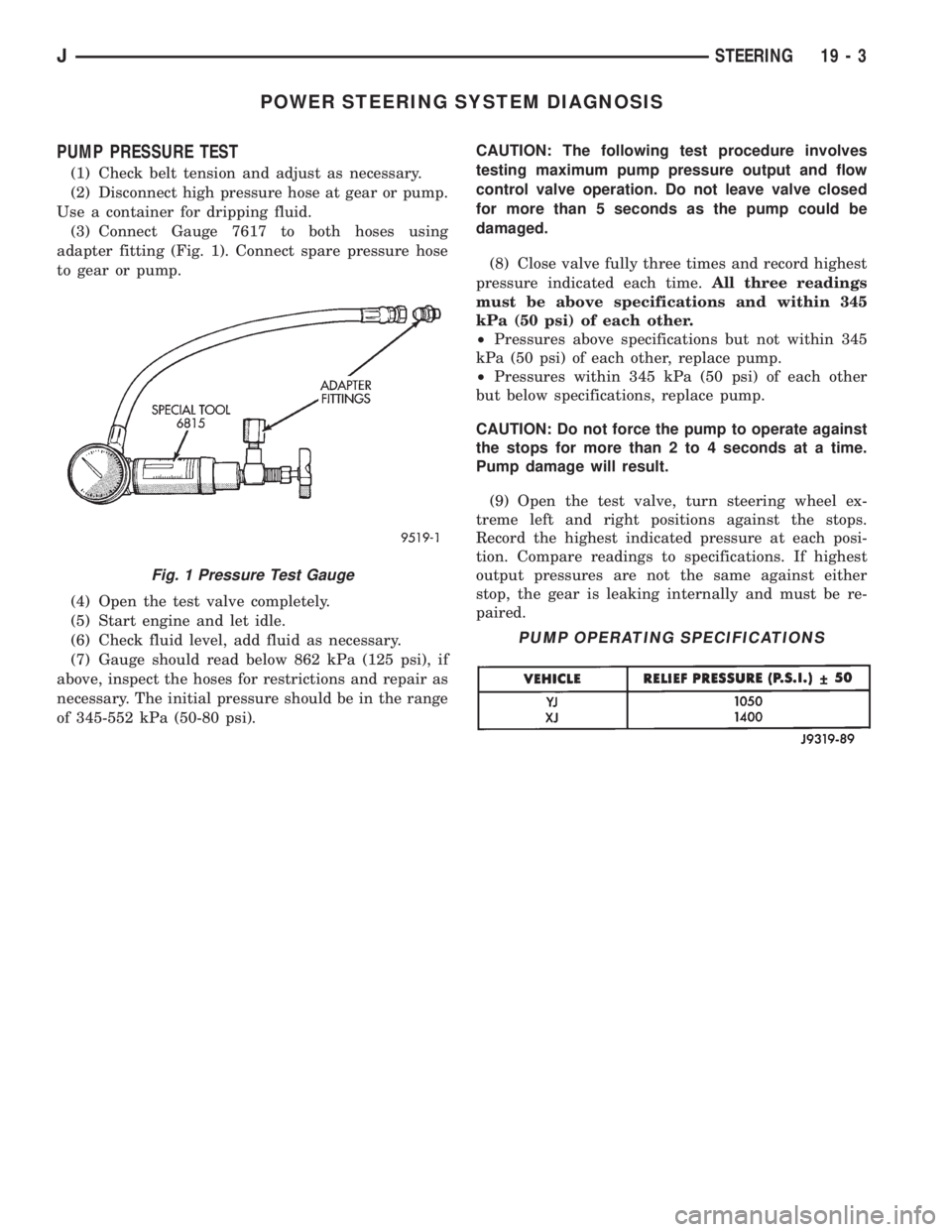
(3) Connect Gauge 7617 to both hoses using
adapter fitting (Fig. 1). Connect spare pressure hose
to gear or pump.
(4) Open the test valve completely.
(5) Start engine and let idle.
(6) Check fluid level, add fluid as necessary.
(7) Gauge should read below 862 kPa (125 psi), if
above, inspect the hoses for restrictions and repair as
necessary. The initial pressure should be in the range
of 345-552 kPa (50-80 psi).CAUTION: The following test procedure involves
testing maximum pump pressure output and flow
control valve operation. Do not leave valve closed
for more than 5 seconds as the pump could be
damaged.
(8) Close valve fully three times and record highest
pressure indicated each time.All three readings
must be above specifications and within 345
kPa (50 psi) of each other.
²Pressures above specifications but not within 345
kPa (50 psi) of each other, replace pump.
²Pressures within 345 kPa (50 psi) of each other
but below specifications, replace pump.
CAUTION: Do not force the pump to operate against
the stops for more than 2 to 4 seconds at a time.
Pump damage will result.
(9) Open the test valve, turn steering wheel ex-
treme left and right positions against the stops.
Record the highest indicated pressure at each posi-
tion. Compare readings to specifications. If highest
output pressures are not the same against either
stop, the gear is leaking internally and must be re-
paired.
Fig. 1 Pressure Test Gauge
PUMP OPERATING SPECIFICATIONS
JSTEERING 19 - 3
Page 1907 of 2158
WHEELS AND TIRES
CONTENTS
page page
SPECIFICATIONS........................ 12
TIRES.................................. 1VEHICLE VIBRATION..................... 10
WHEELS................................ 6
TIRES
INDEX
page page
Cleaning of Tires.......................... 2
General Information........................ 1
Pressure Gauges.......................... 2
Repairing Leaks........................... 3
Replacement Tires......................... 2Rotation................................. 3
Tire Inflation Pressures...................... 2
Tire Noise or Vibration...................... 4
Tire Wear Patterns......................... 4
Tread Wear Indicators....................... 3
GENERAL INFORMATION
Tires are designed for each specific vehicle. They
provide the best overall performance for normal oper-
ation. The ride and handling characteristics match
the vehicle's requirements. With proper care they
will give excellent reliability, traction, skid resis-
tance, and tread life. These tires have specific load
carrying capacities. When correctly inflated, they will
operate properly.
Tires used in cool climates, and with light loads
will have a longer life than tires used in hot climates
with heavy loads. Abrasive road surfaces will acceler-
ate tire wear.
Driving habits have more effect on tire life than
any other factor. Careful drivers will obtain much
greater mileage than careless drivers.
Driving habits that shorten the life of any tire;
²Rapid acceleration and deceleration
²Severe application of brakes
²High-speed driving
²Taking turns at excessive speeds
²Striking curbs and other obstacles
It is very important to follow the tire rotation in-
terval
IDENTIFICATION
Tire type, size, aspect ratio and speed rating are
encoded in the letters and numbers imprinted on the
side wall of the tire. Refer to the chart to decipher
the tire identification code (Fig. 1).Performance tires will have a speed rating letter
after the aspect ratio number. The speed rating is not
always printed on the tire sidewall. The letterSin-
dicates that the tire is speed rated up to 112 mph.
²Qup to 100 mph
²Tup to 118 mph
²Uup to 124 mph
²Hup to 130 mph
²Vup to 149 mph
²Zmore than 149 mph (consult the tire manufac-
turer for the specific speed rating)
An All Season type tire will have eitherM+S,M
&SorMÐS(indicating mud and snow traction) im-
printed on the side wall.
RADIAL-PLY TIRES
Radial-ply tires improve handling, tread life, ride
quality and decrease rolling resistance.
Radial-ply tires must always be used in sets of
four. Under no circumstances should they be used on
the front only. They may be mixed with temporary
spare tires when necessary, but reduced speeds are
recommended.
Radial-ply tires have the same load-carrying capac-
ity as other types of tires of the same size. They use
the same recommended inflation pressures.
SPARE TIRE (TEMPORARY)
The compact spare tire is designed for emergency
use only. The original tire should be repaired and re-
installed at the first opportunity. Refer to Owner's
Manual for complete details.
JWHEELS AND TIRES 22 - 1
Page 1998 of 2158
INTERIOR COMPONENTS
INDEX
page page
Assist HandleÐXJ........................ 89
B/C-Pillar and Liftgate Pillar Trim CoversÐXJ.... 88
Bucket Seat Cushion and CoverÐXJ........... 81
Bucket Seat PlatformÐXJ................... 82
Bucket Seatback Cover and FrameÐXJ........ 81
Cargo BarrierÐXJ........................ 101
Cargo LampÐXJ......................... 94
Carpets and Floor MatsÐXJ................. 99
Dome LampÐXJ......................... 93
Front Bucket SeatsÐXJ.................... 81
Front Carpet/MatÐXJ...................... 99
Front Inner Scuff Plate/Cowl Side Trim PanelÐXJ . 86
Front Shoulder Belt/BuckleÐXJ............... 90
Full Floor ConsoleÐXJ..................... 95
HeadlinerÐXJ............................ 92
I/P Ash Receiver Tray LampÐXJ.............. 80
Instrument Cluster BezelÐXJ................ 80
Interior Trim Panels and Scuff PlatesÐXJ....... 84
Jack StorageÐXJ......................... 97
Keyless Entry ReceiverÐXJ................. 93Mini-Console with Floor ShiftÐXJ............. 94
Mini-Floor ConsoleÐXJ..................... 94
Outer Scuff PlatesÐXJ..................... 89
Overhead ConsoleÐXJ..................... 93
Parking Brake Handle CoverÐXJ............. 94
Quarter and Wheelhouse Trim PanelsÐXJ...... 87
Quarter Trim Panel ExtensionÐXJ............. 87
Rear Carpet/MatÐXJ..................... 100
Rear Seat Cushion CoverÐXJ............... 82
Rear Seat CushionÐXJ.................... 82
Rear Seatback CoverÐXJ................... 84
Rear Seatback Latch Striker and BumperÐXJ.... 84
Rear SeatbackÐXJ........................ 83
Rear Shoulder/Lap Belt/BuckleÐXJ............ 91
Sound BarÐXJ........................... 94
Spare Tire/Wheel Holddown and Floor
BracketsÐXJ........................... 98
SunvisorsÐXJ........................... 93
Windshield Side MoldingÐXJ................ 86
INSTRUMENT CLUSTER BEZELÐXJ
REMOVAL
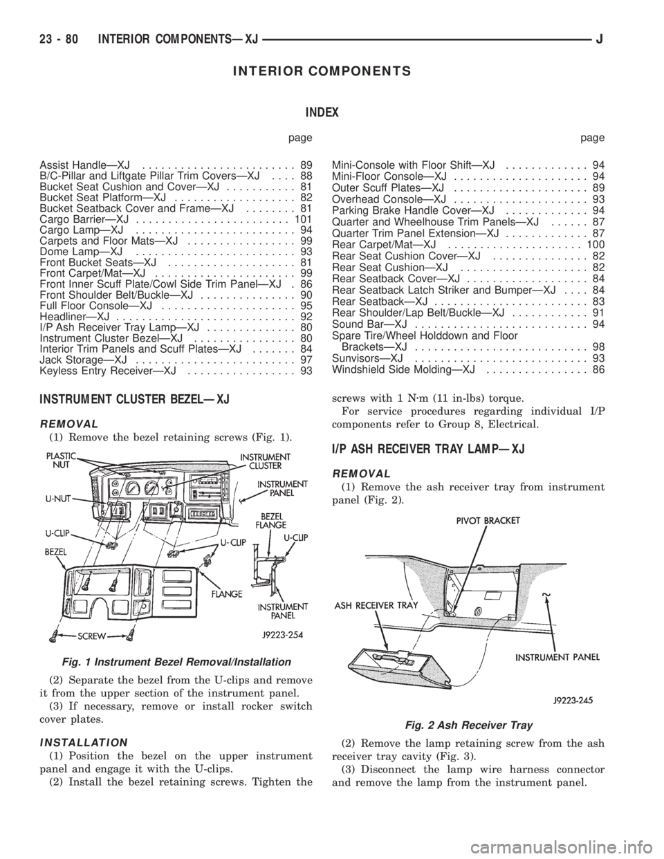
(1) Remove the bezel retaining screws (Fig. 1).
(2) Separate the bezel from the U-clips and remove
it from the upper section of the instrument panel.
(3) If necessary, remove or install rocker switch
cover plates.
INSTALLATION
(1) Position the bezel on the upper instrument
panel and engage it with the U-clips.
(2) Install the bezel retaining screws. Tighten thescrews with 1 Nzm (11 in-lbs) torque.
For service procedures regarding individual I/P
components refer to Group 8, Electrical.
I/P ASH RECEIVER TRAY LAMPÐXJ
REMOVAL
(1) Remove the ash receiver tray from instrument
panel (Fig. 2).
(2) Remove the lamp retaining screw from the ash
receiver tray cavity (Fig. 3).
(3) Disconnect the lamp wire harness connector
and remove the lamp from the instrument panel.
Fig. 1 Instrument Bezel Removal/Installation
Fig. 2 Ash Receiver Tray
23 - 80 INTERIOR COMPONENTSÐXJJ
Page 2016 of 2158
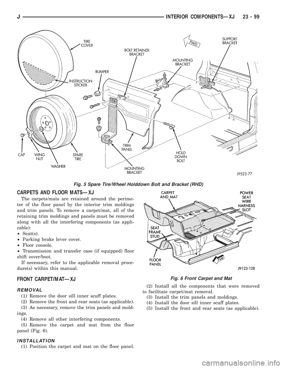
SPARE TIRE/WHEEL HOLDDOWN AND FLOOR
BRACKETSÐXJ
REMOVAL
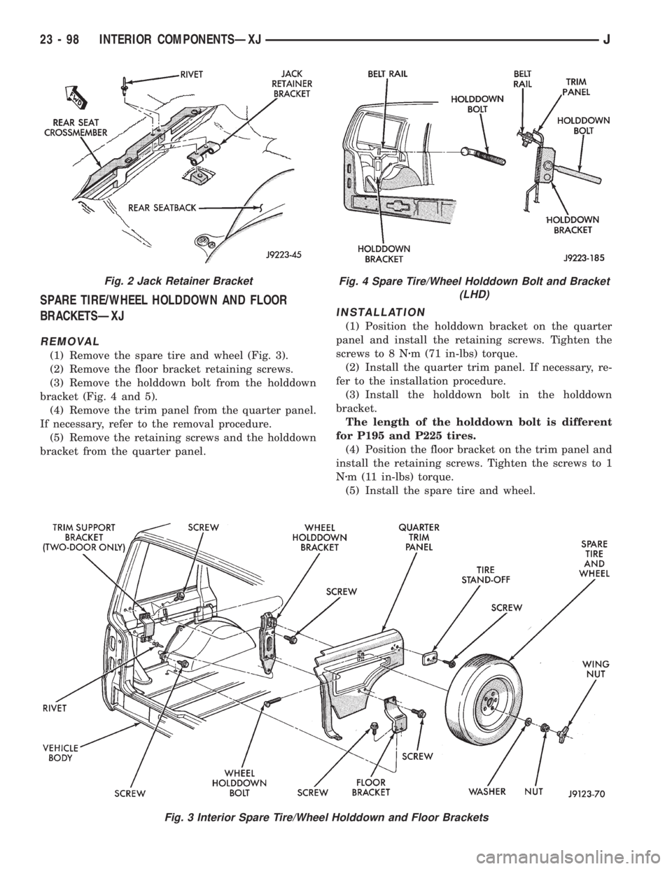
(1) Remove the spare tire and wheel (Fig. 3).
(2) Remove the floor bracket retaining screws.
(3) Remove the holddown bolt from the holddown
bracket (Fig. 4 and 5).
(4) Remove the trim panel from the quarter panel.
If necessary, refer to the removal procedure.
(5) Remove the retaining screws and the holddown
bracket from the quarter panel.
INSTALLATION
(1) Position the holddown bracket on the quarter
panel and install the retaining screws. Tighten the
screws to 8 Nzm (71 in-lbs) torque.
(2) Install the quarter trim panel. If necessary, re-
fer to the installation procedure.
(3) Install the holddown bolt in the holddown
bracket.
The length of the holddown bolt is different
for P195 and P225 tires.
(4) Position the floor bracket on the trim panel and
install the retaining screws. Tighten the screws to 1
Nzm (11 in-lbs) torque.
(5) Install the spare tire and wheel.
Fig. 3 Interior Spare Tire/Wheel Holddown and Floor Brackets
Fig. 2 Jack Retainer BracketFig. 4 Spare Tire/Wheel Holddown Bolt and Bracket
(LHD)
23 - 98 INTERIOR COMPONENTSÐXJJ
Page 2017 of 2158
CARPETS AND FLOOR MATSÐXJ
The carpets/mats are retained around the perime-
ter of the floor panel by the interior trim moldings
and trim panels. To remove a carpet/mat, all of the
retaining trim moldings and panels must be removed
along with all the interfering components (as appli-
cable):
²Seat(s).
²Parking brake lever cover.
²Floor console.
²Transmission and transfer case (if equipped) floor
shift cover/boot.
If necessary, refer to the applicable removal proce-
dure(s) within this manual.
FRONT CARPET/MATÐXJ
REMOVAL
(1) Remove the door sill inner scuff plates.
(2) Remove the front and rear seats (as applicable).
(3) As necessary, remove the trim panels and mold-
ings.
(4) Remove all other interfering components.
(5) Remove the carpet and mat from the floor
panel (Fig. 6).
INSTALLATION
(1) Position the carpet and mat on the floor panel.(2) Install all the components that were removed
to facilitate carpet/mat removal.
(3) Install the trim panels and moldings.
(4) Install the door sill inner scuff plates.
(5) Install the front and rear seats (as applicable).
Fig. 5 Spare Tire/Wheel Holddown Bolt and Bracket (RHD)
Fig. 6 Front Carpet and Mat
JINTERIOR COMPONENTSÐXJ 23 - 99
Page 2022 of 2158
EXTERIOR COMPONENTS
INDEX
page page
Battery TrayÐYJ......................... 110
Body Side Step MoldingÐYJ................ 115
Body Stripes/DecalsÐYJ................... 116
Cowl Grille and ScreenÐYJ................ 109
Cowl Weatherstrip SealÐYJ................ 109
Exterior Nameplates (Adhesive-Backed)ÐYJ.... 120
External Spare/Wheel Tire CarrierÐYJ........ 133
Fender FlareÐYJ........................ 114
Fender Inner Splash ShieldsÐYJ............. 116
Fender Splash ApronsÐYJ................. 115
FendersÐYJ............................ 110
Fuel Filler Protector/NozzleÐYJ............. 121
Half Metal Door Mirror (External)ÐYJ......... 121
Hard Top Liftgate GlassÐYJ................ 124
Hard Top RepairÐYJ..................... 127
Hard Top Roof VentÐYJ................... 127
Hard TopÐYJ........................... 126Hood AlignmentÐYJ...................... 107
Hood Insulator PanelÐYJ.................. 107
Hood Safety LatchÐYJ.................... 109
HoodÐYJ.............................. 107
Liftgate Glass Weatherstrip Seal ReplacementÐYJ. 125
Radiator Grille AppliqueÐYJ................ 104
Soft Top Service InformationÐYJ............. 127
Soft Top ServiceÐYJ..................... 129
Sport BarÐYJ........................... 132
Tailgate AdjustmentÐYJ................... 121
Tailgate HingeÐYJ....................... 121
Tailgate Latch and Release HandleÐYJ........ 122
Tailgate Latch StrikerÐYJ.................. 123
Tailgate Lock CylinderÐYJ................. 122
Tailgate Weatherstrip SealÐYJ.............. 123
TailgateÐYJ............................ 121
Wheelhouse Splash LinersÐYJ.............. 115
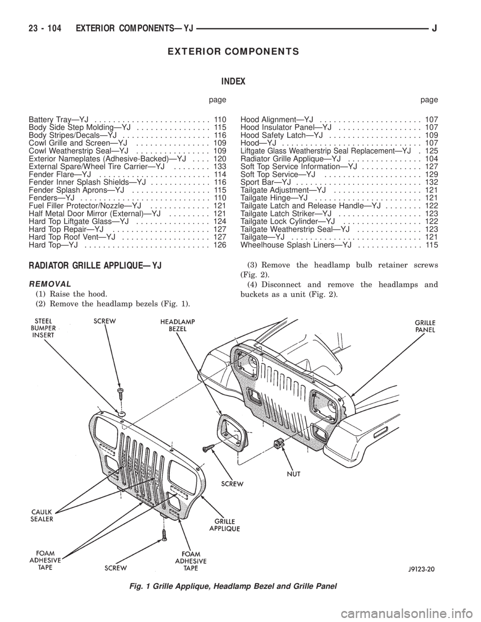
RADIATOR GRILLE APPLIQUEÐYJ
REMOVAL
(1) Raise the hood.
(2) Remove the headlamp bezels (Fig. 1).(3) Remove the headlamp bulb retainer screws
(Fig. 2).
(4) Disconnect and remove the headlamps and
buckets as a unit (Fig. 2).
Fig. 1 Grille Applique, Headlamp Bezel and Grille Panel
23 - 104 EXTERIOR COMPONENTSÐYJJ