1995 JEEP YJ ground clearance
[x] Cancel search: ground clearancePage 28 of 2158

JUMP STARTING, TOWING AND HOISTING
INDEX
page page
Four-Wheel-Drive Vehicle Towing............. 12
Ground Clearance and Ramp Angle............ 11
Hoisting Recommendations.................. 10
Jump Starting Procedure..................... 9Towing Recommendations................... 10
Towing When Keys Are Not Available.......... 13
Two-Wheel-Drive Vehicle TowingÐXJ.......... 11
JUMP STARTING PROCEDURE
WARNING: DO NOT ATTEMPT TO PUSH OR TOW A
VEHICLE TO START THE ENGINE. UNBURNED
FUEL COULD ENTER THE EXHAUST CATALYTIC
CONVERTER AND IGNITE AFTER THE ENGINE IS
STARTED. THIS COULD CAUSE THE CONVERTER
TO OVERHEAT AND RUPTURE.
WARNING: REVIEW ALL SAFETY PRECAUTIONS
AND WARNINGS IN GROUP 8A, BATTERY/START-
ING/CHARGING SYSTEMS DIAGNOSTICS.
DO NOT JUMP START A FROZEN BATTERY, PER-
SONAL INJURY CAN RESULT.
DO NOT JUMP START WHEN MAINTENANCE
FREE BATTERY INDICATOR DOT IS YELLOW OR
BRIGHT COLOR.
DO NOT JUMP START A VEHICLE WHEN THE
BATTERY FLUID IS BELOW THE TOP OF LEAD
PLATES.
DO NOT ALLOW JUMPER CABLE CLAMPS TO
TOUCH EACH OTHER WHEN CONNECTED TO A
BOOSTER SOURCE.
DO NOT USE OPEN FLAME NEAR BATTERY.
REMOVE METALLIC JEWELRY WORN ON HANDS
OR WRISTS TO AVOID INJURY BY ACCIDENTAL
ARCING OF BATTERY CURRENT.
WHEN USING A HIGH OUTPUT BOOSTING DE-
VICE, DO NOT ALLOW BATTERY VOLTAGE TO EX-
CEED 16 VOLTS. REFER TO INSTRUCTIONS
PROVIDED WITH DEVICE BEING USED.
CAUTION: When using another vehicle as a
booster, do not allow vehicles to touch. Electrical
systems can be damaged on either vehicle.
TO JUMP START A DISABLED VEHICLE:
(1) Raise hood on disabled vehicle and visually in-
spect engine compartment for:
²Battery cable clamp condition, clean if necessary.
²Frozen battery.
²Yellow or bright color test indicator, if equipped.
²Low battery fluid level.
²Generator drive belt condition and tension.²Fuel fumes or leakage, correct if necessary.
CAUTION: If the cause of starting problem on dis-
abled vehicle is severe, damage to booster vehicle
charging system can result.
(2) When using another vehicle as a booster
source, turn off all accessories, place gear selector in
park or neutral, set park brake and operate engine at
1200 rpm.
(3) On disabled vehicle, place gear selector in park
or neutral and set park brake. Turn off all accesso-
ries.
(4) Connect jumper cables to booster battery. RED
clamp to positive terminal (+). BLACK clamp to neg-
ative terminal (-). DO NOT allow clamps at opposite
end of cables to touch, electrical arc will result. Re-
view all warnings in this procedure.
(5) On disabled vehicle, connect RED jumper cable
clamp to positive (+) terminal. Connect BLACK
jumper cable clamp to engine ground as close to the
ground cable attaching point as possible (Fig. 1).
Fig. 1 Jumper Cable ConnectionsÐTypical
JLUBRICATION AND MAINTENANCE 0 - 9
Page 30 of 2158

²Do not allow passengers to ride in a vehicle being
towed.
²Always observe state and local laws regarding tow-
ing regulations.²Do not tow a vehicle in a manner that could jeop-
ardize the safety of the operator, pedestrians or other
motorists.
²Do not attach tow chains, T-hooks, J-hooks, or a
tow sling to a bumper, steering linkage, drive shafts
or a non-reinforced frame hole.
GROUND CLEARANCE AND RAMP ANGLE
GROUND CLEARANCE
CAUTION: If vehicle is towed with wheels removed,
install lug nuts to retain brake drums.
A towed vehicle should be raised until lifted wheels
are a minimum 100 mm (4 in) from the ground. Be
sure there is adequate ground clearance at the oppo-
site end of the vehicle, especially when towing over
rough terrain or steep rises in the road. If necessary,
remove the wheels from the lifted end of the vehicle
and lower the vehicle closer to the ground, to in-
crease the ground clearance at the opposite end of
the vehicle. Install lug nuts on wheel attaching studs
to retain brake drums.
FLAT-BED TOWING RAMP ANGLE
If a vehicle with flat-bed towing equipment is used,
the approach ramp angle should not exceed 15 de-
grees.
TWO-WHEEL-DRIVE VEHICLE TOWINGÐXJ
Chrysler Corporation recommends that a vehicle be
towed with the rear end lifted, whenever possible.
TOWING-REAR END LIFTED (SLING-TYPE)
CAUTION: Do not use steering column lock to se-
cure steering wheel during towing operation.
2WD XJ vehicles can be towed with the front
wheels on the surface for extended distances at
speeds not exceeding 48 km/h (30 mph).
(1) Attach J-hooks around the axle shaft tube out-
board of the shock absorber.
(2) Place the sling crossbar under and forward of
the bumper.
(3) Attach safety chains around the frame rails.
(4) Turn the ignition switch to the OFF position to
unlock the steering wheel.
(5) Secure steering wheel in the straight ahead po-
sition with a clamp device designed for towing.
(6) Verify that steering components are in good
condition.
(7) Shift the transmission to NEUTRAL.
Fig. 3 Correct Vehicle Lifting LocationsÐTypical
Fig. 4 Tow Vehicles With Approved Equipment.
JLUBRICATION AND MAINTENANCE 0 - 11
Page 1307 of 2158
(2) Use Valve Spring Compressor Tool
MD-998772A and compress each valve spring.
(3) Remove the valve locks, retainers, springs and
valve stem oil seals. Discard the oil seals.
(4) Use an Arkansas smooth stone or a jewelers
file to remove any burrs on the top of the valve stem,
especially around the groove for the locks.
(5) Remove the valves, and place them in a rack in
the same order as removed.
VALVE CLEANING
Clean all carbon deposits from the combustion
chambers, valve ports, valve stems, valve stem
guides and head.
Clean all grime and gasket material from the en-
gine cylinder head machined gasket surface.
INSPECTION
Inspect for cracks in the combustion chambers and
valve ports.
Inspect for cracks on the exhaust seat.
Inspect for cracks in the gasket surface at each
coolant passage.
Inspect valves for burned, cracked or warped
heads.
Inspect for scuffed or bent valve stems.
Replace valves displaying any damage.
VALVE REFACING
(1) Use a valve refacing machine to reface the in-
take and exhaust valves to the specified angle.
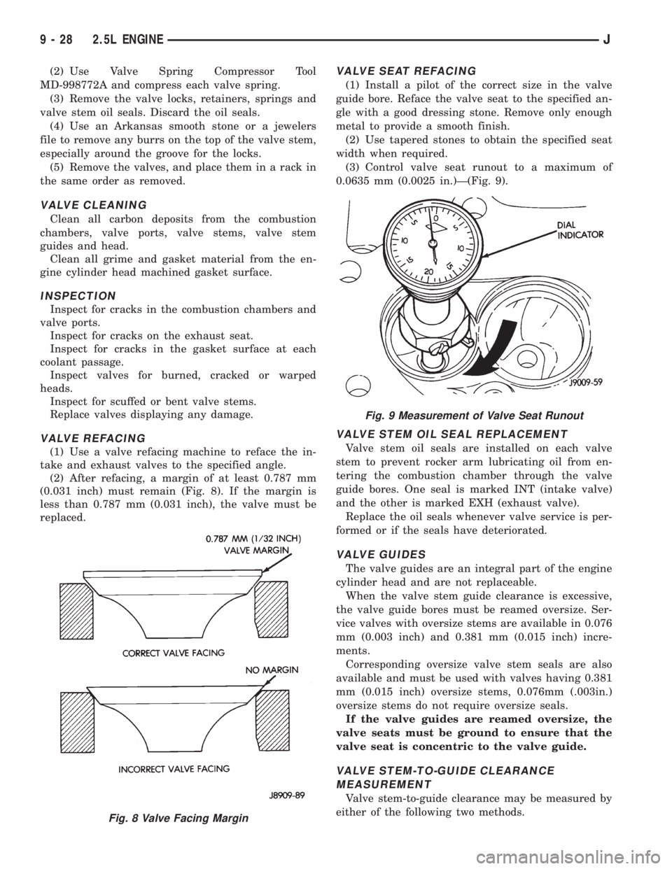
(2) After refacing, a margin of at least 0.787 mm
(0.031 inch) must remain (Fig. 8). If the margin is
less than 0.787 mm (0.031 inch), the valve must be
replaced.
VALVE SEAT REFACING
(1) Install a pilot of the correct size in the valve
guide bore. Reface the valve seat to the specified an-
gle with a good dressing stone. Remove only enough
metal to provide a smooth finish.
(2) Use tapered stones to obtain the specified seat
width when required.
(3) Control valve seat runout to a maximum of
0.0635 mm (0.0025 in.)Ð(Fig. 9).
VALVE STEM OIL SEAL REPLACEMENT
Valve stem oil seals are installed on each valve
stem to prevent rocker arm lubricating oil from en-
tering the combustion chamber through the valve
guide bores. One seal is marked INT (intake valve)
and the other is marked EXH (exhaust valve).
Replace the oil seals whenever valve service is per-
formed or if the seals have deteriorated.
VALVE GUIDES
The valve guides are an integral part of the engine
cylinder head and are not replaceable.
When the valve stem guide clearance is excessive,
the valve guide bores must be reamed oversize. Ser-
vice valves with oversize stems are available in 0.076
mm (0.003 inch) and 0.381 mm (0.015 inch) incre-
ments.
Corresponding oversize valve stem seals are also
available and must be used with valves having 0.381
mm (0.015 inch) oversize stems, 0.076mm (.003in.)
oversize stems do not require oversize seals.
If the valve guides are reamed oversize, the
valve seats must be ground to ensure that the
valve seat is concentric to the valve guide.
VALVE STEM-TO-GUIDE CLEARANCE
MEASUREMENT
Valve stem-to-guide clearance may be measured by
either of the following two methods.
Fig. 8 Valve Facing Margin
Fig. 9 Measurement of Valve Seat Runout
9 - 28 2.5L ENGINEJ
Page 1308 of 2158
PREFERRED METHOD:
(1) Remove the valve from the head.
(2) Clean the valve stem guide bore with solvent
and a bristle brush.
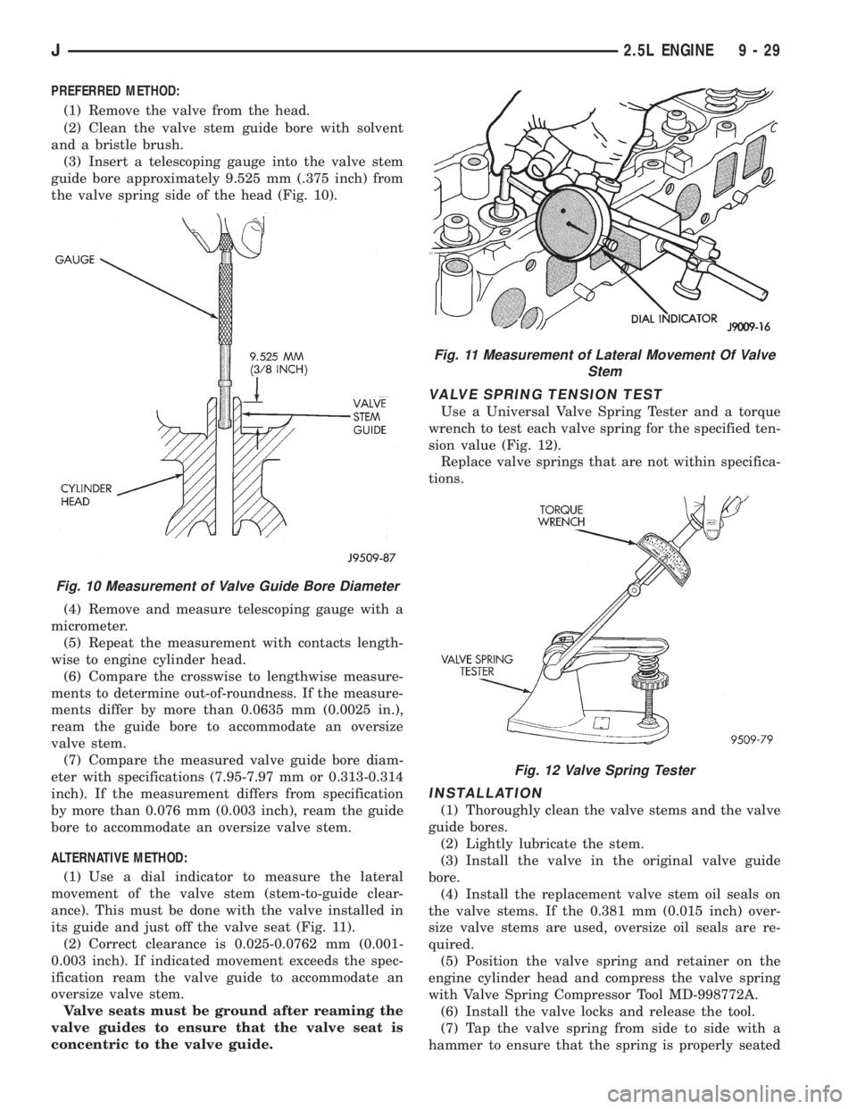
(3) Insert a telescoping gauge into the valve stem
guide bore approximately 9.525 mm (.375 inch) from
the valve spring side of the head (Fig. 10).
(4) Remove and measure telescoping gauge with a
micrometer.
(5) Repeat the measurement with contacts length-
wise to engine cylinder head.
(6) Compare the crosswise to lengthwise measure-
ments to determine out-of-roundness. If the measure-
ments differ by more than 0.0635 mm (0.0025 in.),
ream the guide bore to accommodate an oversize
valve stem.
(7) Compare the measured valve guide bore diam-
eter with specifications (7.95-7.97 mm or 0.313-0.314
inch). If the measurement differs from specification
by more than 0.076 mm (0.003 inch), ream the guide
bore to accommodate an oversize valve stem.
ALTERNATIVE METHOD:
(1) Use a dial indicator to measure the lateral
movement of the valve stem (stem-to-guide clear-
ance). This must be done with the valve installed in
its guide and just off the valve seat (Fig. 11).
(2) Correct clearance is 0.025-0.0762 mm (0.001-
0.003 inch). If indicated movement exceeds the spec-
ification ream the valve guide to accommodate an
oversize valve stem.
Valve seats must be ground after reaming the
valve guides to ensure that the valve seat is
concentric to the valve guide.
VALVE SPRING TENSION TEST
Use a Universal Valve Spring Tester and a torque
wrench to test each valve spring for the specified ten-
sion value (Fig. 12).
Replace valve springs that are not within specifica-
tions.
INSTALLATION
(1) Thoroughly clean the valve stems and the valve
guide bores.
(2) Lightly lubricate the stem.
(3) Install the valve in the original valve guide
bore.
(4) Install the replacement valve stem oil seals on
the valve stems. If the 0.381 mm (0.015 inch) over-
size valve stems are used, oversize oil seals are re-
quired.
(5) Position the valve spring and retainer on the
engine cylinder head and compress the valve spring
with Valve Spring Compressor Tool MD-998772A.
(6) Install the valve locks and release the tool.
(7) Tap the valve spring from side to side with a
hammer to ensure that the spring is properly seated
Fig. 10 Measurement of Valve Guide Bore Diameter
Fig. 11 Measurement of Lateral Movement Of Valve
Stem
Fig. 12 Valve Spring Tester
J2.5L ENGINE 9 - 29
Page 1349 of 2158
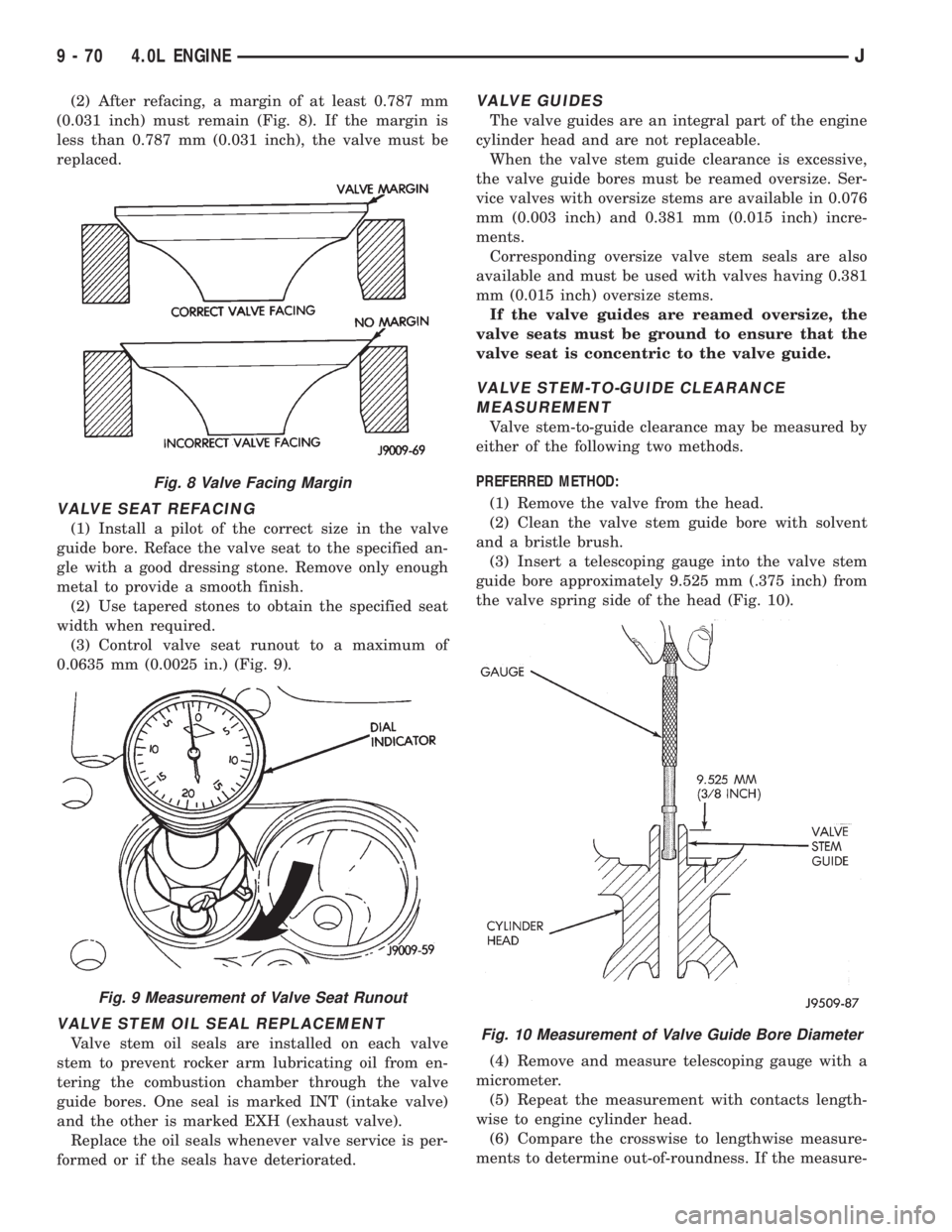
(2) After refacing, a margin of at least 0.787 mm
(0.031 inch) must remain (Fig. 8). If the margin is
less than 0.787 mm (0.031 inch), the valve must be
replaced.
VALVE SEAT REFACING
(1) Install a pilot of the correct size in the valve
guide bore. Reface the valve seat to the specified an-
gle with a good dressing stone. Remove only enough
metal to provide a smooth finish.
(2) Use tapered stones to obtain the specified seat
width when required.
(3) Control valve seat runout to a maximum of
0.0635 mm (0.0025 in.) (Fig. 9).
VALVE STEM OIL SEAL REPLACEMENT
Valve stem oil seals are installed on each valve
stem to prevent rocker arm lubricating oil from en-
tering the combustion chamber through the valve
guide bores. One seal is marked INT (intake valve)
and the other is marked EXH (exhaust valve).
Replace the oil seals whenever valve service is per-
formed or if the seals have deteriorated.
VALVE GUIDES
The valve guides are an integral part of the engine
cylinder head and are not replaceable.
When the valve stem guide clearance is excessive,
the valve guide bores must be reamed oversize. Ser-
vice valves with oversize stems are available in 0.076
mm (0.003 inch) and 0.381 mm (0.015 inch) incre-
ments.
Corresponding oversize valve stem seals are also
available and must be used with valves having 0.381
mm (0.015 inch) oversize stems.
If the valve guides are reamed oversize, the
valve seats must be ground to ensure that the
valve seat is concentric to the valve guide.
VALVE STEM-TO-GUIDE CLEARANCE
MEASUREMENT
Valve stem-to-guide clearance may be measured by
either of the following two methods.
PREFERRED METHOD:
(1) Remove the valve from the head.
(2) Clean the valve stem guide bore with solvent
and a bristle brush.
(3) Insert a telescoping gauge into the valve stem
guide bore approximately 9.525 mm (.375 inch) from
the valve spring side of the head (Fig. 10).
(4) Remove and measure telescoping gauge with a
micrometer.
(5) Repeat the measurement with contacts length-
wise to engine cylinder head.
(6) Compare the crosswise to lengthwise measure-
ments to determine out-of-roundness. If the measure-
Fig. 10 Measurement of Valve Guide Bore Diameter
Fig. 8 Valve Facing Margin
Fig. 9 Measurement of Valve Seat Runout
9 - 70 4.0L ENGINEJ
Page 1350 of 2158
ments differ by more than 0.0635 mm (0.0025 in.),
ream the guide bore to accommodate an oversize
valve stem.
(7) Compare the measured valve guide bore diam-
eter with specifications (7.95-7.97 mm or 0.313-0.314
inch). If the measurement differs from specification
by more than 0.076 mm (0.003 inch), ream the guide
bore to accommodate an oversize valve stem.
ALTERNATIVE METHOD:
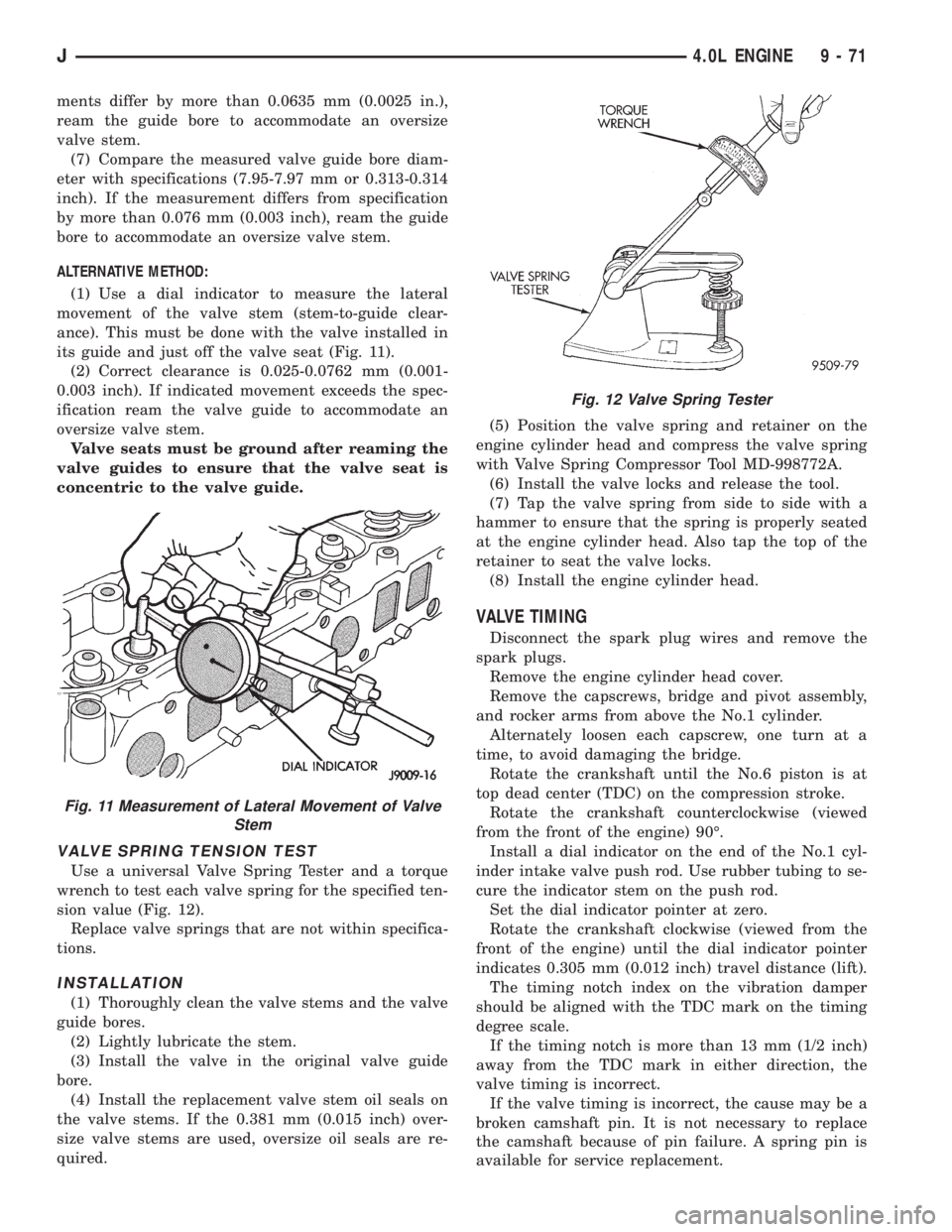
(1) Use a dial indicator to measure the lateral
movement of the valve stem (stem-to-guide clear-
ance). This must be done with the valve installed in
its guide and just off the valve seat (Fig. 11).
(2) Correct clearance is 0.025-0.0762 mm (0.001-
0.003 inch). If indicated movement exceeds the spec-
ification ream the valve guide to accommodate an
oversize valve stem.
Valve seats must be ground after reaming the
valve guides to ensure that the valve seat is
concentric to the valve guide.
VALVE SPRING TENSION TEST
Use a universal Valve Spring Tester and a torque
wrench to test each valve spring for the specified ten-
sion value (Fig. 12).
Replace valve springs that are not within specifica-
tions.
INSTALLATION
(1) Thoroughly clean the valve stems and the valve
guide bores.
(2) Lightly lubricate the stem.
(3) Install the valve in the original valve guide
bore.
(4) Install the replacement valve stem oil seals on
the valve stems. If the 0.381 mm (0.015 inch) over-
size valve stems are used, oversize oil seals are re-
quired.(5) Position the valve spring and retainer on the
engine cylinder head and compress the valve spring
with Valve Spring Compressor Tool MD-998772A.
(6) Install the valve locks and release the tool.
(7) Tap the valve spring from side to side with a
hammer to ensure that the spring is properly seated
at the engine cylinder head. Also tap the top of the
retainer to seat the valve locks.
(8) Install the engine cylinder head.
VALVE TIMING
Disconnect the spark plug wires and remove the
spark plugs.
Remove the engine cylinder head cover.
Remove the capscrews, bridge and pivot assembly,
and rocker arms from above the No.1 cylinder.
Alternately loosen each capscrew, one turn at a
time, to avoid damaging the bridge.
Rotate the crankshaft until the No.6 piston is at
top dead center (TDC) on the compression stroke.
Rotate the crankshaft counterclockwise (viewed
from the front of the engine) 90É.
Install a dial indicator on the end of the No.1 cyl-
inder intake valve push rod. Use rubber tubing to se-
cure the indicator stem on the push rod.
Set the dial indicator pointer at zero.
Rotate the crankshaft clockwise (viewed from the
front of the engine) until the dial indicator pointer
indicates 0.305 mm (0.012 inch) travel distance (lift).
The timing notch index on the vibration damper
should be aligned with the TDC mark on the timing
degree scale.
If the timing notch is more than 13 mm (1/2 inch)
away from the TDC mark in either direction, the
valve timing is incorrect.
If the valve timing is incorrect, the cause may be a
broken camshaft pin. It is not necessary to replace
the camshaft because of pin failure. A spring pin is
available for service replacement.
Fig. 11 Measurement of Lateral Movement of Valve
Stem
Fig. 12 Valve Spring Tester
J4.0L ENGINE 9 - 71
Page 2125 of 2158
- XJ, ANTENNA REMOVE/INSTALL........8F-8
- XJ, GENERAL INFORMATION...........8K-1
- XJ, MULTI-FUNCTION SWITCH..........8J-4
- XJ, MULTI-FUNCTION SWITCH
REMOVE/INSTALL.....................8J-5
- XJ, RADIO REMOVE/INSTALL...........8F-6
- XJ, SOUND BAR REMOVE/INSTALL......8F-8
- XJ, SPEAKERS REMOVE/INSTALL........8F-6
- XJ, TURN SIGNAL/HAZARD WARNING
SYSTEM.............................8J-3
- YJ, ANTENNA REMOVE/INSTALL.......8F-10
- YJ, BUZZER MODULE SCHEMATIC......8U-4
- YJ, GENERAL INFORMATION..........8K-10
- YJ, HAZARD WARNING SYSTEM........8J-4
- YJ, RADIO REMOVE/INSTALL...........8F-9
- YJ, SERVICE PROCEDURES...........8K-17
- YJ, SOUND BAR REMOVE/INSTALL.....8F-10
- YJ, SPEAKERS REMOVE/INSTALL........8F-9
- YJ, TURN SIGNAL SYSTEM............8J-3
- YJ, TURN SIGNAL/HAZARD WARNING
SWITCH REMOVE/INSTALL..............8J-5
30RH/32RH AUTOMATIC TRANSMISSION . . 21-67
30RH/32RH GENERAL SPECIFICATIONS . . 21-335
30RH/32RH IN-VEHICLE SERVICE........21-99
30RH/32RH PRESSURE TEST
SPECIFICATIONS....................21-336
30RH/32RH TORQUE SPECIFICATIONS . . . 21-336
30RH/32RH TRANSMISSION DIAGNOSIS . . 21-70
30RH/32RH TRANSMISSION OVERHAUL . 21-119
30RH/32RH TRANSMISSION REMOVAL
AND INSTALLATION..................21-115
4-CYLINDER ENGINE, ENGINE FIRING
ORDERÐ2.5L.......................8D-32
60-WAY CONNECTOR, POWERTRAIN
CONTROL MODULE (PCM).............14-40
6-CYLINDER ENGINE, AUXILIARY
ELECTRIC COOLING FANÐXJ MODELS
WITH 4.0L...........................7-35
6-CYLINDER ENGINE, ENGINE FIRING
ORDERÐ4.0L.......................8D-32
ABS BRAKE DIAGNOSIS.................5-3
ABS COMPONENT SERVICEABILITY.......5-37
ABS DIAGNOSTIC CONNECTOR.......5-35,5-3
ABS OPERATION AND SERVICE..........5-33
ABS POWER RELAY; ANTI-LOCK BRAKES
(XJ).............................8W-32-1
ABS POWER RELAY; ANTI-LOCK BRAKES
(XJ-RHD).........................8W-32-1
ABS POWER RELAY; ANTI-LOCK BRAKES
(YJ).............................8W-32-1
ABS PUMP MOTOR RELAY; ANTI-LOCK
BRAKES (XJ)......................8W-32-1
ABS PUMP MOTOR RELAY; ANTI-LOCK
BRAKES (XJ-RHD).................8W-32-1
ABS PUMP MOTOR RELAY; ANTI-LOCK
BRAKES (YJ)......................8W-32-1
ABS SYSTEM POWER-UP AND
INITIALIZATION.......................5-35
ABS WARNING LAMP; ANTI-LOCK
BRAKES (XJ)......................8W-32-2
ABS WARNING LAMP; ANTI-LOCK
BRAKES (XJ-RHD).................8W-32-2
ABS WARNING LAMP; ANTI-LOCK
BRAKES (YJ)
......................8W-32-2
ABS WARNING LAMP; INSTRUMENT
CLUSTER (XJ)
.....................8W-40-2
ABS WARNING LAMP; INSTRUMENT
CLUSTER (XJ-RHD)
................8W-40-2
ABS WARNING LAMP; INSTRUMENT
CLUSTER (YJ)
.....................8W-40-2
ABS WARNING LIGHT DISPLAY
...........5-3
ABSOLUTE PRESSURE (MAP) SENSOR,
MANIFOLD; FUEL SYSTEM
.............14-63
ABSOLUTE PRESSURE (MAP) SENSOR,
MANIFOLD; FUEL/IGNITION (YJ)
......8W-30-4
ABSOLUTE PRESSURE (MAP) SENSOR,
MANIFOLD; IGNITION SYSTEMS
....8D-23,8D-5
ABSOLUTE PRESSURE (MAP) SENSOR
TEST, MANIFOLD; FUEL SYSTEM
........14-47
ABSOLUTE PRESSURE (MAP) SENSOR
TEST, MANIFOLD; IGNITION SYSTEMS
....8D-11
ABSOLUTE PRESSURE (MAP)
SENSORÐPCM INPUT, MANIFOLD
.......14-23
ABSOLUTE PRESSURE SENSOR,
MANIFOLD; FUEL/IGNITION (XJ)
......8W-30-4
ABSOLUTE PRESSURE SENSOR,
MANIFOLD; FUEL/IGNITION (XJ-RHD)
. . 8W-30-4ABSORBER, SHOCK; FRONT
SUSPENSION AND AXLE............2-13,2-16
ABSORBER, SHOCK; REAR SUSPENSION
AND AXLES........................3-4,3-7
A/C BLOWER MOTOR.................24-35
A/C COMPONENTS....................24-4
A/C COMPRESSOR; AIR CONDITIONING/
HEATER (YJ)......................8W-42-2
A/C COMPRESSOR CLUTCH............24-15
A/C COMPRESSOR CLUTCH RELAY . 24-15,24-16
A/C CONDENSER.....................24-34
A/C CONTROL REPLACEMENT, HEATER . . . 24-23
A/C OPERATION, HEATER...............24-1
A/C RECIRCULATING DOOR VACUUM
MOTOR REPLACEMENT...............24-27
ACCELERATION SWITCH; ANTI-LOCK
BRAKES (XJ)......................8W-32-1
ACCELERATION SWITCH; ANTI-LOCK
BRAKES (XJ-RHD).................8W-32-1
ACCELERATION SWITCH; ANTI-LOCK
BRAKES (YJ)......................8W-32-1
ACCELERATION SWITCH; BRAKES........5-35
ACCELERATION SWITCH INSTALLATION....5-39
ACCELERATION SWITCH OPERATION......5-37
ACCELERATION SWITCH REMOVAL.......5-39
ACCELERATOR PEDAL.................14-17
ACCELERATOR PEDAL AND THROTTLE
CABLE........................14-17,14-58
ACCESSORY DRIVE BELT...............0-21
ACCESSORY DRIVE BELTS, ENGINE.......7-38
ACCESSORY LAMP AND HEATER
CONTROL PANEL LAMP; INTERIOR
LIGHTING (YJ)....................8W-44-1
ACCUMULATOR PISTONS AND SPRINGS . 21-189
A/C-HEATER BLOWER MOTOR; AIR
CONDITIONING/HEATER (YJ).........8W-42-2
A/C-HEATER SYSTEM; AIR
CONDITIONING/HEATER (XJ).........8W-42-1
A/C-HEATER SYSTEM; AIR
CONDITIONING/HEATER (XJ-RHD).....8W-42-1
ADD-A-TRUNKÐYJ..................23-157
ADJUSTER/MOTORS, POWER SEAT . . . 8R-1,8R-2
ADJUSTER/MOTORS REMOVE/INSTALL,
POWER SEAT........................8R-3
ADJUSTMENT, BRAKELIGHT SWITCH......5-32
ADJUSTMENT, COMPASS VARIATION......8C-5
ADJUSTMENT, DIFFERENTIAL SHIM
PACK MEASUREMENT..................2-43
ADJUSTMENT, DRUM BRAKE............5-57
ADJUSTMENT, FRONT BAND...........21-102
ADJUSTMENT, GEARSHIFT CABLE/
LINKAGE...........................21-71
ADJUSTMENT, PARK INTERLOCK CABLE . 21-195
ADJUSTMENT PROCEDURES,
TRANSMISSION ASSEMBLY...........21-155
ADJUSTMENT, REAR WHEEL SENSOR
INSTALLATION........................5-38
ADJUSTMENT, SHIFT CABLE...........21-195
ADJUSTMENT, SHIFT LINKAGE . . . 21-286,21-309
ADJUSTMENT, TRANSMISSION
THROTTLE CABLE...................21-194
ADJUSTMENT, TRANSMISSION
THROTTLE VALVE CABLE..............21-71
ADJUSTMENT, VALVE BODY ASSEMBLY . . 21-153
ADJUSTMENT (XJ), PARK INTERLOCK
CABLE............................21-101
ADJUSTMENT (XJ), SHIFT CABLE.......21-100
ADJUSTMENT (XJ/YJ), PARKING BRAKE
CABLE TENSIONER....................5-69
ADJUSTMENT (XJ/YJ), THROTTLE VALVE
CABLE............................21-101
ADJUSTMENT (YJ), SHIFT LINKAGE.....21-100
ADJUSTMENTÐMAJOR, DOOR
ALIGNMENT.........................23-41
ADJUSTMENTÐMINOR, DOOR
ALIGNMENT.........................23-37
ADJUSTMENTÐXJ, DOOR LATCH........23-48
ADJUSTMENTÐXJ, HOOD.............23-10
ADJUSTMENTÐXJ, LIFTGATE...........23-63
ADJUSTMENTÐYJ, TAILGATE..........23-121
ADJUSTMENTS, ALIGNMENT
MEASUREMENTS
......................2-8
ADJUSTMENTS, STEERING GEAR
........19-24
AFTERMARKET PAINT AND TRIM
REPAIR PRODUCTSÐXJ
..............23-159
AFTERMARKET PAINT AND TRIM
REPAIR PRODUCTSÐYJ
..............23-160
AIR CLEANER
.......................14-29AIR CLEANER ELEMENT; EMISSION
CONTROL SYSTEMS...................25-7
AIR CLEANER ELEMENT; FUEL SYSTEM . . . 14-59
AIR CLEANER ELEMENT; LUBRICATION
AND MAINTENANCE...................0-18
AIR CLEANER HOUSING...............14-58
AIR CONDITIONING...................24-37
AIR CONDITIONING (A/C) CLUTCH
RELAY.............................14-58
AIR CONDITIONING (A/C) CLUTCH
RELAYÐPCM OUTPUT................14-26
AIR CONDITIONING (A/C) CONTROLSÐ
PCM INPUT.........................14-21
AIR CONDITIONING CONTROLSÐXJ
VEHICLES..........................24-15
AIR CONDITIONING CONTROLSÐYJ
VEHICLES..........................24-16
AIR CONDITIONING, HEATER; AIR
CONDITIONING/HEATER (YJ).........8W-42-2
AIR CONDITIONING OPERATION; AIR
CONDITIONING/HEATER (XJ).........8W-42-2
AIR CONDITIONING OPERATION; AIR
CONDITIONING/HEATER (XJ-RHD).....8W-42-2
AIR CONDITIONING PERFORMANCE
TESTS.............................24-12
AIR CONDITIONING SCHEMATICÐXJ......24-5
AIR CONDITIONING TEST PROCEDURES,
HEATING...........................24-15
AIR CONTROL (IAC) MOTOR, IDLE; FUEL
SYSTEM............................14-62
AIR CONTROL (IAC) MOTOR, IDLE;
FUEL/IGNITION (XJ)................8W-30-2
AIR CONTROL (IAC) MOTOR, IDLE;
FUEL/IGNITION (YJ)................8W-30-2
AIR CONTROL (IAC) MOTOR, IDLE;
FUEL/IGNITION (XJ-RHD)............8W-30-2
AIR CONTROL (IAC) MOTORÐPCM
OUTPUT, IDLE.......................14-27
AIR CONTROL MOTOR TEST, IDLE.......14-49
AIR DEFLECTORÐXJ, COWL
WEATHERSTRIP SEAL/CROSSMEMBER . . . 23-11
AIR DOOR VACUUM MOTOR, FRESH.....24-34
AIR EXHAUST GRILLEÐXJ.............23-25
AIR GAP, SPEED SENSOR...............5-37
AIR INTAKE DUCT, FRESH..............24-34
AIR PRESSURE TEST.................21-74
AIR TEMPERATURE SENSOR, INTAKE;
FUEL/IGNITION (XJ)................8W-30-4
AIR TEMPERATURE SENSOR, INTAKE;
FUEL/IGNITION (YJ)................8W-30-4
AIR TEMPERATURE SENSOR, INTAKE;
FUEL/IGNITION (XJ-RHD)............8W-30-4
AIR TEMPERATURE SENSOR, INTAKE
MANIFOLD; FUEL SYSTEM.............14-60
AIR TEMPERATURE SENSOR, INTAKE
MANIFOLD; IGNITION SYSTEMS....8D-23,8D-5
AIR TEMPERATURE, SENSOR
RESISTANCE (OHMS)ÐCOOLANT
TEMPERATURE SENSOR/MANIFOLD......14-46
AIR TEMPERATURE SENSOR TEST,
INTAKE MANIFOLD; FUEL SYSTEM.......14-46
AIR TEMPERATURE SENSOR TEST,
INTAKE MANIFOLD; IGNITION
SYSTEMS..........................8D-11
AIR TEMPERATURE SENSORÐPCM
INPUT, INTAKE MANIFOLD.............14-22
AIRBAG MODULE.....................8M-1
AIRBAG MODULE HANDLING............8M-2
AIRBAG MODULE REMOVE/INSTALL......8M-3
AIRBAG MODULE REMOVEÐINSTALL....19-49
AIRBAG SYSTEM; RESTRAINT SYSTEMS . . 8M-1
AIRBAG SYSTEM; STEERING...........19-47
AIRBAG SYSTEM SERVICE (DEPLOYED) . . . 8M-2
AIR-CONDITIONER COMPRESSOR........0-21
ALIGNMENT ADJUSTMENTÐMAJOR,
DOOR.............................23-41
ALIGNMENT ADJUSTMENTÐMINOR,
DOOR.............................23-37
ALIGNMENT, FRONT WHEEL..............2-5
ALIGNMENTÐXJ, HEADLAMP...........8L-6
ALIGNMENTÐYJ, HEADLAMP
..........8L-22
ALIGNMENTÐYJ, HOOD
..............23-107
ANCHOR AND BUMPERÐXJ, LIFTGATE
LICENSE PLATE SCREW
...............23-65
ANGLE, GROUND CLEARANCE AND
RAMP
..............................0-11
ANGLE MEASUREMENT, UNIVERSAL
JOINT
..............................16-4
JINDEX 1
Description Group-Page Description Group-Page Description Group-Page
Page 2128 of 2158
BUMPERÐXJ, LIFTGATE LICENSE PLATE
SCREW ANCHOR.....................23-65
BUMPERÐXJ, REAR SEATBACK LATCH
STRIKER...........................23-84
BUMPERS......................13-16,13-5
BUS, CCD; FUEL/IGNITION (XJ).......8W-30-5
BUSHING AND PISTON CLEARANCE,
AW-4 .............................21-339
BUSHING REPLACEMENT, AXLE......2-12,2-34
BUSHING REPLACEMENT, LEAF SPRING
EYE; FRONT SUSPENSION AND AXLE.....2-17
BUSHING REPLACEMENT, LEAF SPRING
EYE; REAR SUSPENSION AND AXLES . . . 3-5,3-7
BUSHINGS, CLUTCH AND BRAKE PEDAL . . . 0-22
BUZZER, COMBINATION; INTERIOR
LIGHTING (YJ)....................8W-44-1
BUZZER MODULE.................8U-1,8U-2
BUZZER MODULE SCHEMATIC - YJ.......8U-4
CABLE, ACCELERATOR PEDAL AND
THROTTLE.....................14-17,14-58
CABLE ADJUSTMENT, PARK INTERLOCK . 21-195
CABLE ADJUSTMENT, SHIFT...........21-195
CABLE ADJUSTMENT, TRANSMISSION
THROTTLE.........................21-194
CABLE ADJUSTMENT, TRANSMISSION
THROTTLE VALVE....................21-71
CABLE ADJUSTMENT (XJ), PARK
INTERLOCK........................21-101
CABLE ADJUSTMENT (XJ), SHIFT.......21-100
CABLE ADJUSTMENT (XJ/YJ), THROTTLE
VALVE..............................21-101
CABLE REMOVE/INSTALL, SERVO.......8H-10
CABLE REPLACEMENT, TRANSMISSION
THROTTLE.........................21-193
CABLE REPLACEMENT (XJ), PARKING
BRAKE REAR.........................5-67
CABLE REPLACEMENT (YJ), PARKING
BRAKE FRONT........................5-67
CABLE REPLACEMENT (YJ), PARKING
BRAKE REAR.........................5-68
CABLE REPLACEMENTÐXJ, LATCH
RELEASE...........................23-11
CABLE RESISTANCE, SPARK PLUG......8D-14
CABLE, SERVO.......................8H-1
CABLE, SPEEDOMETER.................0-33
CABLE TENSIONER ADJUSTMENT
(XJ/YJ), PARKING BRAKE...............5-69
CABLE TENSIONER REPLACEMENT (XJ),
PARKING BRAKE......................5-66
CABLE, THROTTLE...................14-17
CABLE/LINKAGE ADJUSTMENT,
GEARSHIFT.........................21-71
CABLES, DISTRIBUTOR CAP AND
ROTOR, IGNITION.....................0-20
CABLES, SPARK PLUG SECONDARY.....8D-14,
8D-24
CABLES, VENT DOOR CONTROL.........24-32
CALIBRATION, COMPASS...............8C-5
CALIPER ASSEMBLY...................5-50
CALIPER CLEANING AND INSPECTION.....5-50
CALIPER DISASSEMBLY................5-48
CALIPER INSTALLATION................5-51
CALIPER OPERATION AND WEAR
COMPENSATION......................5-45
CALIPER REMOVAL....................5-48
CAMSHAFT......................9-32,9-74
CAMSHAFT PIN REPLACEMENT......9-34,9-75
CAMSHAFT POSITION SENSOR; FUEL
SYSTEM............................14-60
CAMSHAFT POSITION SENSOR;
FUEL/IGNITION (XJ)................8W-30-3
CAMSHAFT POSITION SENSOR;
FUEL/IGNITION (YJ)................8W-30-3
CAMSHAFT POSITION SENSOR;
IGNITION SYSTEMS..............8D-17,8D-2
CAMSHAFT POSITION SENSOR;
FUEL/IGNITION (XJ-RHD)............8W-30-3
CAMSHAFT POSITION SENSOR TEST;
FUEL SYSTEM.......................14-46
CAMSHAFT POSITION SENSOR TEST;
IGNITION SYSTEMS
...................8D-6
CAMSHAFT POSITION SENSORÐPCM
INPUT
.............................14-22
(CANADA ONLY)ÐXJ, DAYTIME
RUNNING LIGHTS
....................8L-15
(CANADA ONLY)ÐYJ, DAYTIME
RUNNING LIGHTS
....................8L-30
CANISTER, EVAP
..................25-4,25-7CAP AND ROTOR, IGNITION CABLES,
DISTRIBUTOR........................0-20
CAP, DISTRIBUTOR....................8D-7
CAP, FUEL TANK FILLER TUBE;
EMISSION CONTROL SYSTEMS......25-4,25-7
CAP, FUEL TANK FILLER TUBE; FUEL
SYSTEM............................14-13
CAP, RADIATOR PRESSURE.............7-25
CAPACITIES, COOLING SYSTEM..........7-45
CAPACITIES, FLUID.....................0-3
CAPACITIES, FUEL TANK..........14-13,14-67
CAPACITY TEST, FUEL PUMP............14-7
CAR REPLACEMENT, PITMAN SHAFT
SEALSÐIN.........................19-23
CARDAN (CV), DOUBLE................16-11
CARDAN, SINGLE....................16-10
CARGO BARRIERÐXJ................23-101
CARGO LAMP AND DOME LAMP;
INTERIOR LIGHTING (XJ-RHD)........8W-44-1
CARGO LAMP, COURTESY LAMPS AND
DOME LAMP; INTERIOR LIGHTING (XJ) . 8W-44-1
CARGO LAMPÐXJ...................23-94
CARPET/MATÐXJ, FRONT.............23-99
CARPET/MATÐXJ, REAR.............23-100
CARPETÐYJ.......................23-156
CARPETS AND FLOOR MATSÐXJ.......23-99
CARRIERÐYJ, EXTERNAL SPARE/
WHEEL TIRE.......................23-133
CASE (4WD VEHICLES), TRANSFER........0-24
CASE ASSEMBLY, TRANSFER....21-294,21-319
CASE CHANGES, TRANSFER...........21-307
CASE CLEANING AND INSPECTION,
TRANSMISSION.....................21-125
CASE COVER OIL SEAL REPLACEMENT,
TIMING.........................9-30,9-73
CASE COVER, TIMING..............9-31,9-72
CASE DISASSEMBLY AND OVERHAUL,
TRANSFER...................21-289,21-310
CASE IDENTIFICATION, TRANSFER.....21-284,
21-307
CASE INSTALLATION, TRANSFER . 21-288,21-309
CASE LUBRICANT AND FILL LEVEL,
TRANSFER.........................21-284
CASE, NP231 TRANSFER.......21-283,21-305
CASE, NP242 TRANSFER.......21-307,21-331
CASE OVERHAUL, FIRST-REVERSE
BRAKE PISTON AND TRANSMISSION....21-247
CASE REMOVAL, TRANSFER.....21-287,21-309
CASE SKID PLATE, TRANSFER......13-15,13-3
CASE SPECIFICATIONS, TRANSMISSION/
TRANSFER.........................21-333
CATALYTIC CONVERTER............11-1,11-4
CATALYTIC CONVERTOR................25-1
CAUTIONS, AND WARNINGS, NOTES;
WIRING DIAGRAMSÐGENERAL
INFORMATION (XJ)...................8W-1
CCD BUS; FUEL/IGNITION (XJ)........8W-30-5
CENTER HIGH MOUNTED STOP LAMP
(CHMSL)ÐXJ.......................8L-12
CENTER HIGH MOUNTED STOP LAMP
(CHMSL)ÐYJ.......................8L-28
CERTIFICATION LABEL, VEHICLE SAFETY . Intro.-4
CHAIN AND SPROCKETS, TIMING....9-31,9-73
CHANGE AND FILTER REPLACEMENT,
ENGINE OIL
..........................0-16
CHANGE, LUBRICANT; FRONT
SUSPENSION AND AXLE
................2-23
CHANGE, LUBRICANT; REAR
SUSPENSION AND AXLES
...........3-13,3-31
CHANGE, REFILLING AFTER OVERHAUL
OR FLUID/FILTER
..............21-100,21-182
CHANGES AND PARTS
INTERCHANGEABILITY, TRANSMISSION
. . . 21-67
CHANGES, TRANSFER CASE
...........21-307
CHANNEL REPLACEMENTÐYJ, DOOR
FRAME GLASS
......................23-142
CHARGING, BATTERY
..................8A-7
CHARGING REFRIGERANT SYSTEM
......24-11
CHARGING SYSTEM; BATTERY/
STARTING/CHARGING SYSTEMS
DIAGNOSTICS
.......................8A-17
CHARGING SYSTEM; CHARGING
SYSTEM (XJ)
.....................8W-20-1
CHARGING SYSTEM; CHARGING
SYSTEM (XJ-RHD)
.................8W-20-1
CHARGING SYSTEM; CHARGING
SYSTEM (YJ)
.....................8W-20-1CHARGING SYSTEM INDICATOR LAMP;
INSTRUMENT CLUSTER (XJ).........8W-40-3
CHARGING SYSTEM SPECIFICATIONS....8A-23
CHARGING TIME TABLE, BATTERY........8A-8
CHART, MAIN BEARING FITTING......9-48,9-90
CHART, XJ PERFORMANCE
TEMPERATURE AND PRESSURE.........24-13
CHART, YJ PERFORMANCE
TEMPERATURE AND PRESSURE.........24-13
CHARTÐAX 15 MANUAL
TRANSMISSION, SELECTIVE SNAP
RING.............................21-334
CHARTS, BRAKELINE..................5-12
CHARTS, DIAGNOSIS GUIDES...........21-77
CHARTS, GEARTRAIN OPERATION AND
APPLICATION.......................21-169
CHARTS, INSPECTION AND DIAGNOSIS.....6-4
CHASSIS AND BODY COMPONENTS.......0-28
CHASSIS COMPONENT AND WHEEL
BEARING LUBRICANTS.................0-28
CHECK VALVE TEST, POWER BOOSTER.....5-9
CHECKING FLUID LEVEL AND
CONDITION........................21-182
CHECKS, PRELIMINARY.................7-5
CHIME/BUZZER MODULE; INTERIOR
LIGHTING (XJ)....................8W-44-2
CHIME/BUZZER MODULE; INTERIOR
LIGHTING (XJ-RHD)................8W-44-2
CHMSL LAMPS, STOP LAMPS; REAR
LIGHTING (XJ)....................8W-51-1
CHMSL LAMPS, STOP LAMPS; REAR
LIGHTING (XJ-RHD)................8W-51-1
CHMSL LAMPS, STOP LAMPS; REAR
LIGHTING (YJ)....................8W-51-1
(CHMSL)ÐXJ, CENTER HIGH MOUNTED
STOP LAMP.........................8L-12
(CHMSL)ÐYJ, CENTER HIGH MOUNTED
STOP LAMP.........................8L-28
CIGAR LIGHTER; HORN/CIGAR LIGHTER . . . 8E-1
CIGAR LIGHTER; HORN/CIGAR LIGHTER
(YJ).............................8W-41-1
CIGAR LIGHTER; INSTRUMENT CLUSTER
(XJ).............................8W-40-1
CIRCUIT IDENTIFICATION; WIRING
DIAGRAMSÐGENERAL INFORMATION
(XJ)...............................8W-1
CIRCUIT REMOVE/INSTALL, PRINTED....8E-19,
8E-40
CIRCUIT SENSEÐPCM INPUT, IGNITION . . 14-23
CIRCUIT VOLTAGE, OPEN...............8A-6
CLAMPS, FUEL TUBES/LINES/HOSES . 14-62,14-9
CLASSIFICATION OF LUBRICANTS.........0-2
CLASSIFICATIONS AND RATINGS,
BATTERY...........................8A-23
CLEANER, AIR.......................14-29
CLEANER ELEMENT, AIR; EMISSION
CONTROL SYSTEMS...................25-7
CLEANER ELEMENT, AIR; FUEL SYSTEM . . 14-59
CLEANER ELEMENT, AIR; LUBRICATION
AND MAINTENANCE...................0-18
CLEANER HOUSING, AIR...............14-58
CLEANING AND INSPECTION, CALIPER....5-50
CLEANING AND INSPECTION, GEAR......19-42
CLEANING AND INSPECTION,
TRANSMISSION CASE................21-125
CLEANING OF TIRES...................22-2
CLEANING/INSPECTION; FRONT
SUSPENSION AND AXLE
................2-37
CLEANING/INSPECTION; REAR
SUSPENSION AND AXLES
...............3-20
CLEANING/REVERSE FLUSHING,
COOLING SYSTEM
....................7-22
CLEARANCE AND RAMP ANGLE,
GROUND
............................0-11
CLEARANCE, AW-4 BUSHING AND
PISTON
...........................21-339
CLOCKSPRING
.......................19-51
CLUSTER AND GAUGE HOUSINGSÐYJ,
INSTRUMENT
......................23-151
CLUSTER ASSEMBLY REMOVE/INSTALL
. . 8E-17,
8E-35
CLUSTER BEZELÐXJ, INSTRUMENT
.....23-80
CLUSTER BEZELÐYJ, INSTRUMENT
....23-151
CLUSTER CONNECTORS (RHD)
.........8E-11
CLUSTER, GAUGE PACKAGE
.......8E-31,8E-43
CLUSTER GROUND; INSTRUMENT
CLUSTER (XJ)
.....................8W-40-3
4 INDEXJ
Description Group-Page Description Group-Page Description Group-Page