1995 JEEP YJ roof
[x] Cancel search: roofPage 497 of 2158

REAR WINDOW DEFOGGER
CONTENTS
page page
DIAGNOSIS............................. 1
GENERAL INFORMATION.................. 1SERVICE PROCEDURES................... 3
GENERAL INFORMATION
The electrically-heated rear window defogger is an
available option on XJ (Cherokee), and YJ (Wrangler)
models equipped with the hardtop roof option. Fol-
lowing are general descriptions of the major compo-
nents in the rear window defogger system. Refer to
Group 8W - Wiring Diagrams for complete circuit de-
scriptions and diagrams.
REAR WINDOW GLASS GRID
The heated rear window glass has two electrically-
conductive vertical bus bars and a series of horizon-
tal grid lines made of a silver-ceramic material,
which is baked on and bonded to the inside surface of
the glass. The grid lines and bus bars comprise a
parallel electrical circuit.
When the rear window defogger switch is placed in
the ON position, current is directed to the rear win-
dow grid lines through the bus bars. The grid lines
heat the rear window to clear the surface of fog or
snow. Circuit protection for the heated grid circuit is
provided by fuse 18 (XJ) or fuse 6 (YJ) in the fuse-
block module.
The grid lines and bus bars are highly resistant to
abrasion. However, it is possible for an open to occur
in an individual grid line resulting in no current flow
through the line. The grid lines can be damaged or
scraped off with sharp instruments. Care should be
taken in cleaning the glass or removing foreign ma-
terials, decals or stickers. Normal glass cleaning sol-
vents or hot water used with rags or toweling is
recommended.A repair kit is available to repair the grid lines and
bus bars, or to reinstall the heated glass pigtail
wires.
DEFOGGER SWITCH
The rear window defogger switch is mounted in the
instrument panel left of the steering column for XJ,
or right of the steering column for YJ. The switch cir-
cuit is protected by fuse 8 (XJ) or fuse 9 (YJ) in the
fuseblock module. Actuating the switch energizes the
relay and electronic timer. A light-emitting diode
(LED) in the switch (XJ), or a indicator lamp in the
switch (YJ), illuminates to indicate when the system
is turned on. The defogger switch can not be re-
paired. If faulty, the switch must be replaced.
DEFOGGER RELAY/TIMER
The defogger relay/timer is located in the relay cen-
ter on XJ models, or taped to the instrument panel
wiring harness behind the parking brake pedal in the
left cowl side area on YJ models. When the rear de-
fogger switch is actuated, the rear defogger relay is
energized. This causes current to flow through the
grid circuit for approximately 10 minutes, or until
the rear window defogger switch or ignition switch
are turned off.
DIAGNOSIS
SYSTEM TESTS
Electrically-heated rear window defogger operation
can be confirmed in the following manner:
(1) Turn the ignition switch to the ON position.
(2) Turn rear window defogger control switch ON.
(3) Monitor vehicle voltmeter. With the control
switch ON, a distinct needle deflection should be
noted.(4) The rear window defogger operation can be
checked by feeling the glass. A distinct difference in
temperature between the grid lines and adjacent
clear glass can be detected within 3 to 4 minutes of
operation.
(5) Using a DC voltmeter, contact terminal A (Fig.
1) (passenger side) with the negative lead, and termi-
JREAR WINDOW DEFOGGER 8N - 1
Page 786 of 2158
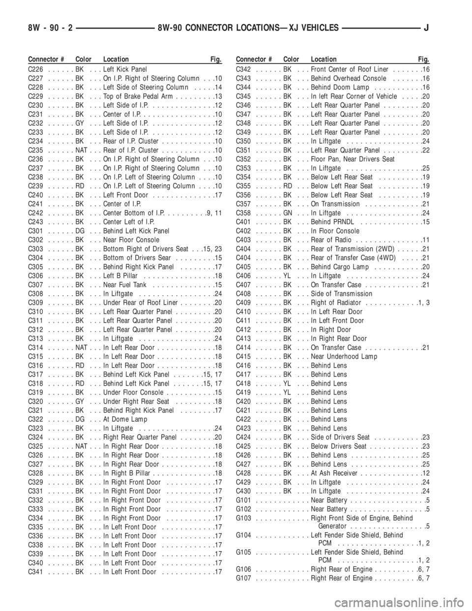
Connector # Color Location Fig.
C226......BK ...Left Kick Panel
C227......BK ...OnI.P.Right of Steering Column . . .10
C228......BK ...Left Side of Steering Column.....14
C229......BK ...TopofBrake Pedal Arm.........13
C230......BK ...Left Side of I.P...............12
C231......BK ...Center of I.P.................10
C232......GY ...Left Side of I.P...............12
C233......BK ...Left Side of I.P...............12
C234......BK ...Rear of I.P. Cluster............10
C235......NAT...Rear of I.P. Cluster............10
C236......BK ...OnI.P.Right of Steering Column . . .10
C237......BK ...OnI.P.Right of Steering Column . . .10
C238......BK ...OnI.P.Left of Steering Column....10
C239......RD ...OnI.P.Left of Steering Column....10
C240......BK ...Left Front Door..............17
C241......BK ...Center of I.P.
C242......BK ...Center Bottom of I.P..........9,11
C243......BK ...Center Left of I.P.
C301......DG ...Behind Left Kick Panel
C302......BK ...Near Floor Console
C303......BK ...Bottom Right of Drivers Seat . . .15, 23
C304......BK ...Bottom of Drivers Sear.........15
C305......BK ...Behind Right Kick Panel........17
C306......BK ...Left B Pillar................18
C307......BK ...Near Fuel Tank..............15
C308......BK ...InLiftgate.................24
C309......BK ...Under Rear of Roof Liner........20
C310......BK ...Left Rear Quarter Panel.........20
C311......BK ...Left Rear Quarter Panel.........20
C312......BK ...Left Rear Quarter Panel.........20
C313......BK ...InLiftgate.................24
C314......NAT...InLeft Rear Door.............18
C315......BK ...InLeft Rear Door.............18
C316......RD ...InLeft Rear Door.............18
C317......BK ...Behind Left Kick Panel.......15, 17
C318......RD ...Behind Left Kick Panel.......15, 17
C319......BK ...Under Floor Console...........15
C320......GY ...Under Right Rear Seat.........18
C321......BK ...Behind Right Kick Panel........17
C322......DG ...AtDome Lamp
C323......BK ...InLiftgate.................24
C324......BK ...Right Rear Quarter Panel........20
C325......NAT...InRight Rear Door............18
C326......BK ...InRight Rear Door............18
C327......BK ...InRight Rear Door............18
C328......BK ...InRight B Pillar..............18
C329......BK ...InRight Front Door...........17
C331......BK ...InRight Front Door...........17
C332......BK ...InRight Front Door...........17
C333......BK ...InRight Front Door...........17
C334......BK ...InRight Front Door...........17
C335......BK ...InLeft Front Door............17
C336......BK ...InLeft Front Door............17
C338......BK ...InLeft Front Door............17
C339......BK ...InLeft Front Door............17
C340......BK ...InLeft Front Door............17
C341......BK ...InLeft Front Door............17Connector # Color Location Fig.
C342......BK ...Front Center of Roof Liner.......16
C343......BK ...Behind Overhead Console.......16
C344......BK ...Behind Doom Lamp...........16
C345......BK ...Inleft Rear Corner of Vehicle.....20
C346......BK ...Left Rear Quarter Panel.........20
C347......BK ...Left Rear Quarter Panel.........20
C348......BK ...Left Rear Quarter Panel.........20
C349......BK ...Left Rear Quarter Panel.........20
C350......BK ...InLiftgate.................24
C351......BK ...Left Rear Quarter Panel.........22
C352......BK ...Floor Pan, Near Drivers Seat
C353......BK ...InLiftgate.................25
C354......BK ...Below Left Rear Seat..........19
C355......RD ...Below Left Rear Seat..........19
C356......BK ...Below Left Rear Seat..........19
C357......BK ...OnTransmission.............21
C358......GN ...InLiftgate.................24
C401......BK ...Behind PRNDL..............15
C402......BK ...InFloor Console
C403......BK ...Rear of Radio...............11
C404......BK ...Rear of Transmission (2WD)......21
C404......BK ...Rear of Transfer Case (4WD).....21
C405......BK ...Behind Cargo Lamp...........20
C406......YL ...InLiftgate.................24
C407......BK ...OnTransfer Case.............21
C408......BK ...Side of Transmission
C409......BK ...Right of Radiator............1,3
C410......BK ...InLeft Rear Door
C411......BK ...InLeft Front Door
C412......BK ...InRight Door
C413......BK ...InRight Rear Door
C414......BK ...OnTransfer Case.............21
C415......BK ...Near Underhood Lamp
C416......BK ...Behind Lens
C417......BK ...Behind Lens
C418......YL ...Behind Lens
C419......YL ...Behind Lens
C420......BK ...Behind Lens
C421......BK ...Behind Lens
C422......BK ...Behind Lens
C423......BK ...Behind Lens
C424......BK ...Side of Drivers Seat...........23
C425......BK ...Below Drivers Seat............23
C426......BK ...Behind Lens................25
C427......BK ...Behind Lens................25
C428......BK ...AtAshReceiver..............12
C429......BK ...InLiftgate.................24
C430......BK ...InLiftgate.................24
G101............Near Battery.................5
G102............Near Battery.................5
G103............Right Front Side of Engine, Behind
Generator.................5
G104............Left Fender Side Shield, Behind
PCM ..................1,2
G105............Left Fender Side Shield, Behind
PCM ..................1,2
G106............Right Rear of Engine..........6,7
G107............Right Rear of Engine..........6,7
8W - 90 - 2 8W-90 CONNECTOR LOCATIONSÐXJ VEHICLESJ
Page 816 of 2158
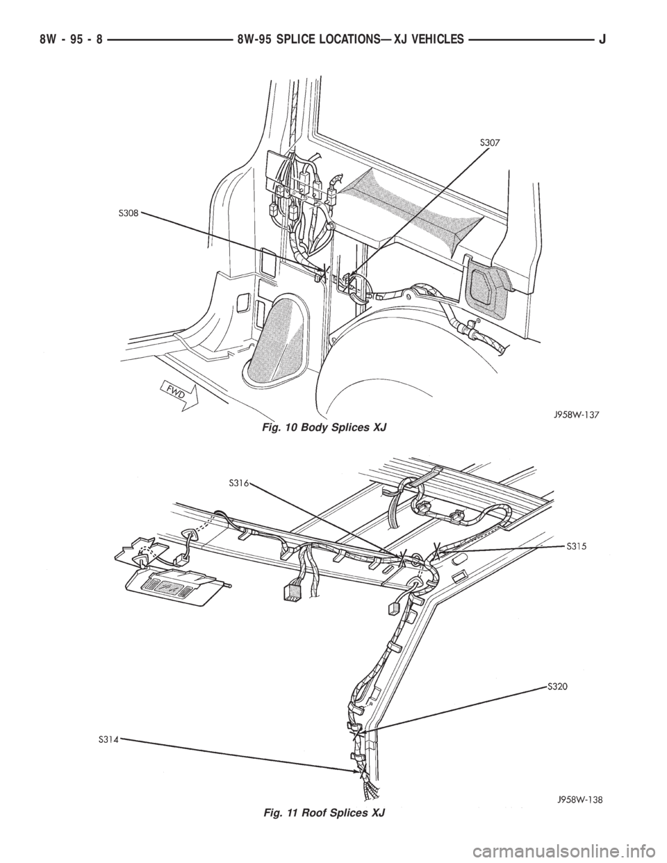
Fig. 10 Body Splices XJ
Fig. 11 Roof Splices XJ
8W - 95 - 8 8W-95 SPLICE LOCATIONSÐXJ VEHICLESJ
Page 1068 of 2158
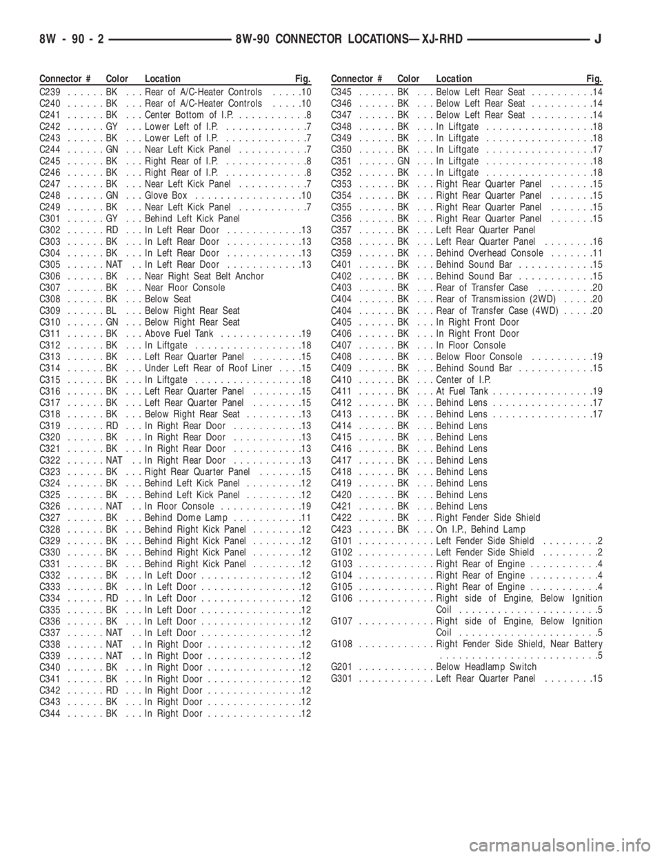
Connector # Color Location Fig.
C239......BK ...Rear of A/C-Heater Controls.....10
C240......BK ...Rear of A/C-Heater Controls.....10
C241......BK ...Center Bottom of I.P............8
C242......GY ...Lower Left of I.P..............7
C243......BK ...Lower Left of I.P..............7
C244......GN ...Near Left Kick Panel...........7
C245......BK ...Right Rear of I.P..............8
C246......BK ...Right Rear of I.P..............8
C247......BK ...Near Left Kick Panel...........7
C248......GN ...Glove Box.................10
C249......BK ...Near Left Kick Panel...........7
C301......GY ...Behind Left Kick Panel
C302......RD ...InLeft Rear Door............13
C303......BK ...InLeft Rear Door............13
C304......BK ...InLeft Rear Door............13
C305......NAT ..InLeft Rear Door............13
C306......BK ...Near Right Seat Belt Anchor
C307......BK ...Near Floor Console
C308......BK ...Below Seat
C309......BL ...Below Right Rear Seat
C310......GN ...Below Right Rear Seat
C311......BK ...Above Fuel Tank.............19
C312......BK ...InLiftgate.................18
C313......BK ...Left Rear Quarter Panel........15
C314......BK ...Under Left Rear of Roof Liner....15
C315......BK ...InLiftgate.................18
C316......BK ...Left Rear Quarter Panel........15
C317......BK ...Left Rear Quarter Panel........15
C318......BK ...Below Right Rear Seat.........13
C319......RD ...InRight Rear Door...........13
C320......BK ...InRight Rear Door...........13
C321......BK ...InRight Rear Door...........13
C322......NAT ..InRight Rear Door...........13
C323......BK ...Right Rear Quarter Panel.......15
C324......BK ...Behind Left Kick Panel.........12
C325......BK ...Behind Left Kick Panel.........12
C326......NAT ..InFloor Console.............19
C327......BK ...Behind Dome Lamp...........11
C328......BK ...Behind Right Kick Panel........12
C329......BK ...Behind Right Kick Panel........12
C330......BK ...Behind Right Kick Panel........12
C331......BK ...Behind Right Kick Panel........12
C332......BK ...InLeft Door................12
C333......BK ...InLeft Door................12
C334......RD ...InLeft Door................12
C335......BK ...InLeft Door................12
C336......BK ...InLeft Door................12
C337......NAT ..InLeft Door................12
C338......NAT ..InRight Door...............12
C339......NAT ..InRight Door...............12
C340......BK ...InRight Door...............12
C341......BK ...InRight Door...............12
C342......RD ...InRight Door...............12
C343......BK ...InRight Door...............12
C344......BK ...InRight Door...............12Connector # Color Location Fig.
C345......BK ...Below Left Rear Seat..........14
C346......BK ...Below Left Rear Seat..........14
C347......BK ...Below Left Rear Seat..........14
C348......BK ...InLiftgate.................18
C349......BK ...InLiftgate.................18
C350......BK ...InLiftgate.................17
C351......GN ...InLiftgate.................18
C352......BK ...InLiftgate.................18
C353......BK ...Right Rear Quarter Panel.......15
C354......BK ...Right Rear Quarter Panel.......15
C355......BK ...Right Rear Quarter Panel.......15
C356......BK ...Right Rear Quarter Panel.......15
C357......BK ...Left Rear Quarter Panel
C358......BK ...Left Rear Quarter Panel........16
C359......BK ...Behind Overhead Console.......11
C401......BK ...Behind Sound Bar............15
C402......BK ...Behind Sound Bar............15
C403......BK ...Rear of Transfer Case.........20
C404......BK ...Rear of Transmission (2WD).....20
C404......BK ...Rear of Transfer Case (4WD).....20
C405......BK ...InRight Front Door
C406......BK ...InRight Front Door
C407......BK ...InFloor Console
C408......BK ...Below Floor Console..........19
C409......BK ...Behind Sound Bar............15
C410......BK ...Center of I.P.
C411......BK ...AtFuel Tank................19
C412......BK ...Behind Lens................17
C413......BK ...Behind Lens................17
C414......BK ...Behind Lens
C415......BK ...Behind Lens
C416......BK ...Behind Lens
C417......BK ...Behind Lens
C418......BK ...Behind Lens
C419......BK ...Behind Lens
C420......BK ...Behind Lens
C421......BK ...Behind Lens
C422......BK ...Right Fender Side Shield
C423......BK ...OnI.P.,Behind Lamp
G101............Left Fender Side Shield.........2
G102............Left Fender Side Shield.........2
G103............Right Rear of Engine...........4
G104............Right Rear of Engine...........4
G105............Right Rear of Engine...........4
G106............Right side of Engine, Below Ignition
Coil......................5
G107............Right side of Engine, Below Ignition
Coil......................5
G108............Right Fender Side Shield, Near Battery
.........................5
G201............Below Headlamp Switch
G301............Left Rear Quarter Panel........15
8W - 90 - 2 8W-90 CONNECTOR LOCATIONSÐXJ-RHDJ
Page 1086 of 2158
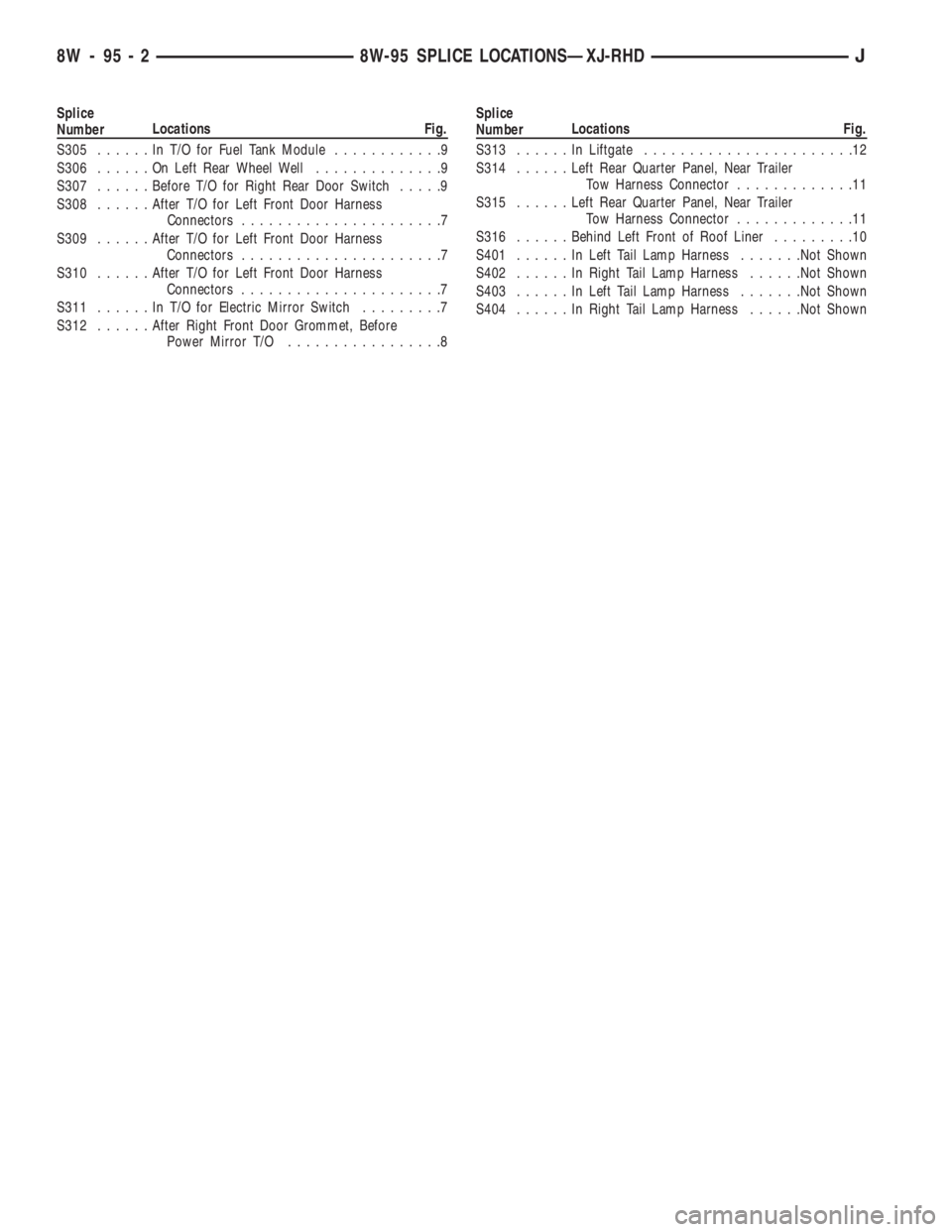
Splice
NumberLocations Fig.
S305......InT/OforFuel Tank Module............9
S306......OnLeft Rear Wheel Well..............9
S307......Before T/O for Right Rear Door Switch.....9
S308......After T/O for Left Front Door Harness
Connectors......................7
S309......After T/O for Left Front Door Harness
Connectors......................7
S310......After T/O for Left Front Door Harness
Connectors......................7
S311......InT/OforElectric Mirror Switch.........7
S312......After Right Front Door Grommet, Before
Power Mirror T/O.................8Splice
NumberLocations Fig.
S313......InLiftgate.......................12
S314......Left Rear Quarter Panel, Near Trailer
Tow Harness Connector.............11
S315......Left Rear Quarter Panel, Near Trailer
Tow Harness Connector.............11
S316......Behind Left Front of Roof Liner.........10
S401......InLeft Tail Lamp Harness.......Not Shown
S402......InRight Tail Lamp Harness......Not Shown
S403......InLeft Tail Lamp Harness.......Not Shown
S404......InRight Tail Lamp Harness......Not Shown
8W - 95 - 2 8W-95 SPLICE LOCATIONSÐXJ-RHDJ
Page 1943 of 2158
(3) Retain the tape stripe/decal firmly against flat
surface and separate the carrier from tape stripe/de-
cal.
(4) Use a sponge and apply solution to the tape
stripe/decal adhesive and to panel surface.
(5) Position the adhesive side of tape stripe/decal
on the panel with the bottom aligned with the char-
acter line.
²Align the end of the replacement tape stripe/decal
with the end of existing tape stripe/decal.
²Correctly align the index darts and index notches.
(6) If a complete replacement tape stripe/decal is
not being installed:
²Position the replacement tape stripe/decal section
at the center of the repair area.
²Align it with the existing tape stripe/decal.
²Allow at least 12 mm (1/2 in) of the tape stripe/de-
cal section to overlap the tape stripe/decal edges.
(7) Apply the wetting solution to the outer side of
the tape stripe/decal.
CAUTION: Avoid unnecessary pulling and stretch-
ing at the ends.
(8) Slide a squeegee from the center to the ends of
the tape stripe/decal. Use firm strokes to remove all
of the air bubbles.
(9) If a wrinkle is trapped in the tape stripe/decal
stop immediately. Lift the wrinkled area and re-align
it with the character line to remove the wrinkle.Do
not lift the tape stripe/decal if only a few air
bubbles exist.
(10) Where applicable, allow 12 mm (1/2 in) extra
tape stripe/decal to extend beyond edges.
(11) Fold the excess tape onto the inside flange and
adhere it with finger pressure.
(12) Inspect the tape stripe/decal installation with
the reflected light to find any damage.
(13) Remove all the air and moisture bubbles from
the tape stripe/decal with a needle or pin.
(14) Install any removed components and clean the
vehicle as necessary.
QUARTER WINDOW APPLIQUEÐXJ
REMOVAL/INSTALLATION
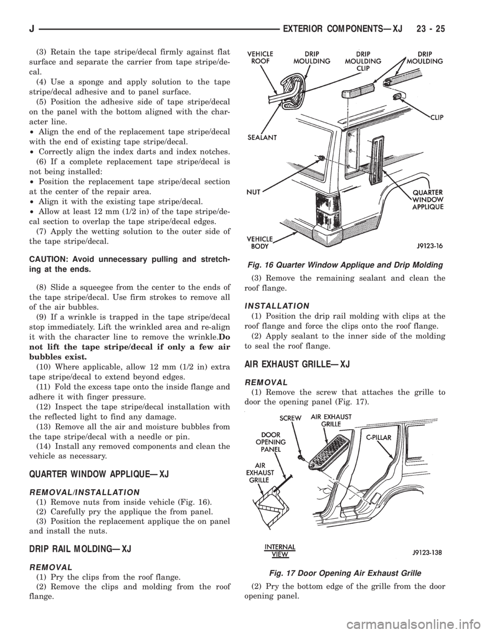
(1) Remove nuts from inside vehicle (Fig. 16).
(2) Carefully pry the applique the from panel.
(3) Position the replacement applique the on panel
and install the nuts.
DRIP RAIL MOLDINGÐXJ
REMOVAL
(1) Pry the clips from the roof flange.
(2) Remove the clips and molding from the roof
flange.(3) Remove the remaining sealant and clean the
roof flange.
INSTALLATION
(1) Position the drip rail molding with clips at the
roof flange and force the clips onto the roof flange.
(2) Apply sealant to the inner side of the molding
to seal the roof flange.
AIR EXHAUST GRILLEÐXJ
REMOVAL
(1) Remove the screw that attaches the grille to
door the opening panel (Fig. 17).
(2) Pry the bottom edge of the grille from the door
opening panel.
Fig. 16 Quarter Window Applique and Drip Molding
Fig. 17 Door Opening Air Exhaust Grille
JEXTERIOR COMPONENTSÐXJ 23 - 25
Page 1946 of 2158
(3) For power/manual mirrors, remove the inside
trim cover.
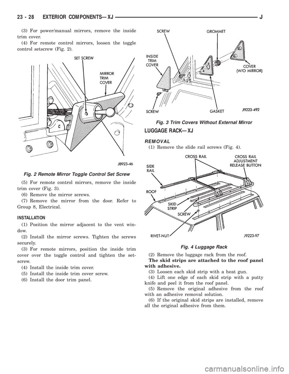
(4) For remote control mirrors, loosen the toggle
control setscrew (Fig. 2).
(5) For remote control mirrors, remove the inside
trim cover (Fig. 3).
(6) Remove the mirror screws.
(7) Remove the mirror from the door. Refer to
Group 8, Electrical.
INSTALLATION
(1) Position the mirror adjacent to the vent win-
dow.
(2) Install the mirror screws. Tighten the screws
securely.
(3) For remote mirrors, position the inside trim
cover over the toggle control and tighten the set-
screw.
(4) Install the inside trim cover.
(5) Install the inside trim cover screw.
(6) Install the door trim panel.
LUGGAGE RACKÐXJ
REMOVAL
(1) Remove the slide rail screws (Fig. 4).
(2) Remove the luggage rack from the roof.
The skid strips are attached to the roof panel
with adhesive.
(3) Loosen each skid strip with a heat gun.
(4) Lift one edge of each skid strip with a putty
knife and peel it from the roof panel.
(5) Remove the original adhesive from the roof
with an adhesive removal solution.
(6) If the original skid strips are installed, remove
all the original adhesive from them.
Fig. 2 Remote Mirror Toggle Control Set Screw
Fig. 3 Trim Covers Without External Mirror
Fig. 4 Luggage Rack
23 - 28 EXTERIOR COMPONENTSÐXJJ
Page 1947 of 2158
INSTALLATION
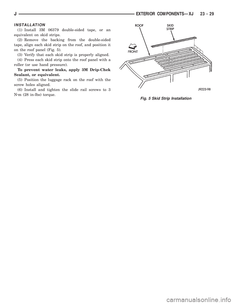
(1) Install 3M 06379 double-sided tape, or an
equivalent on skid strips.
(2) Remove the backing from the double-sided
tape, align each skid strip on the roof, and position it
on the roof panel (Fig. 5).
(3) Verify that each skid strip is properly aligned.
(4) Press each skid strip onto the roof panel with a
roller (or use hand pressure).
To prevent water leaks, apply 3M Drip-Chek
Sealant, or equivalent.
(5) Position the luggage rack on the roof with the
screw holes aligned.
(6) Install and tighten the slide rail screws to 3
Nzm (28 in-lbs) torque.
Fig. 5 Skid Strip Installation
JEXTERIOR COMPONENTSÐXJ 23 - 29