1995 JEEP YJ width
[x] Cancel search: widthPage 1280 of 2158
ENGINES
CONTENTS
page page
LUBRICATION SYSTEM................... 37
LUBRICATION SYSTEM................... 79
2.5L ENGINE SERVICE PROCEDURES....... 134.0L ENGINE SERVICE PROCEDURES....... 55
ENGINE DIAGNOSIS...................... 5
STANDARD SERVICE PROCEDURES......... 1
STANDARD SERVICE PROCEDURES
INDEX
page page
Engine Performance........................ 2
Form-In-Place Gaskets...................... 1
Honing Cylinder Bores...................... 2
Hydrostatic Lock........................... 4Measuring with Plastigage.................... 3
Repair Damaged or Worn Threads............. 4
Service Engine Assembly (Short Block).......... 4
FORM-IN-PLACE GASKETS
There are several places where form-in-place gas-
kets are used on the engine.DO NOT use form-in-
place gasket material unless specified.Care
must be taken when applying form-in-place gaskets.
Bead size, continuity and location are of great impor-
tance. Too thin a bead can result in leakage while too
much can result in spill-over. A continuous bead of
the proper width is essential to obtain a leak-free
joint.
Two types of form-in-place gasket materials are
used in the engine area (Mopar Silicone Rubber Ad-
hesive Sealant and Mopar Gasket Maker). Each have
different properties and cannot be used interchange-
ably.
MOPAR SILICONE RUBBER ADHESIVE
SEALANT
Mopar Silicone Rubber Adhesive Sealant, normally
black in color, is available in 3 ounce tubes. Moisture
in the air causes the sealant material to cure. This
material is normally used on flexible metal flanges.
It has a shelf life of a year and will not properly cure
if over aged. Always inspect the package for the ex-
piration date before use.
MOPAR GASKET MAKER
Mopar Gasket Maker, normally red in color, is
available in 6 cc tubes. This anaerobic type gasket
material cures in the absence of air when squeezedbetween smooth machined metallic surfaces. It will
not cure if left in the uncovered tube. DO NOT use
on flexible metal flanges.
SURFACE PREPARATION
Parts assembled with form-in-place gaskets may be
disassembled without unusual effort. In some in-
stances, it may be necessary to lightly tap the part
with a mallet or other suitable tool to break the seal
between the mating surfaces. A flat gasket scraper
may also be lightly tapped into the joint but care
must be taken not to damage the mating surfaces.
Scrape or wire brush all gasket surfaces to remove
all loose material. Inspect stamped parts to ensure
gasket rails are flat. Flatten rails with a hammer on
a flat plate, if required. Gasket surfaces must be free
of oil and dirt. Make sure the old gasket material is
removed from blind attaching holes.
GASKET APPLICATION
Assembling parts using a form-in-place gasket re-
quires care.
Mopar Silicone Rubber Adhesive Sealant should be
applied in a continuous bead approximately 3 mm
(0.12 inch) in diameter. All mounting holes must be
circled. For corner sealing,a3or6mm(1/8 or 1/4
inch) drop is placed in the center of the gasket con-
tact area. Uncured sealant may be removed with a
shop towel. Components should be torqued in place
while the sealant is still wet to the touch (within 10
JENGINES 9 - 1
Page 1282 of 2158
CAUTION: DO NOT use engine or transmission oil,
mineral spirits or kerosene.
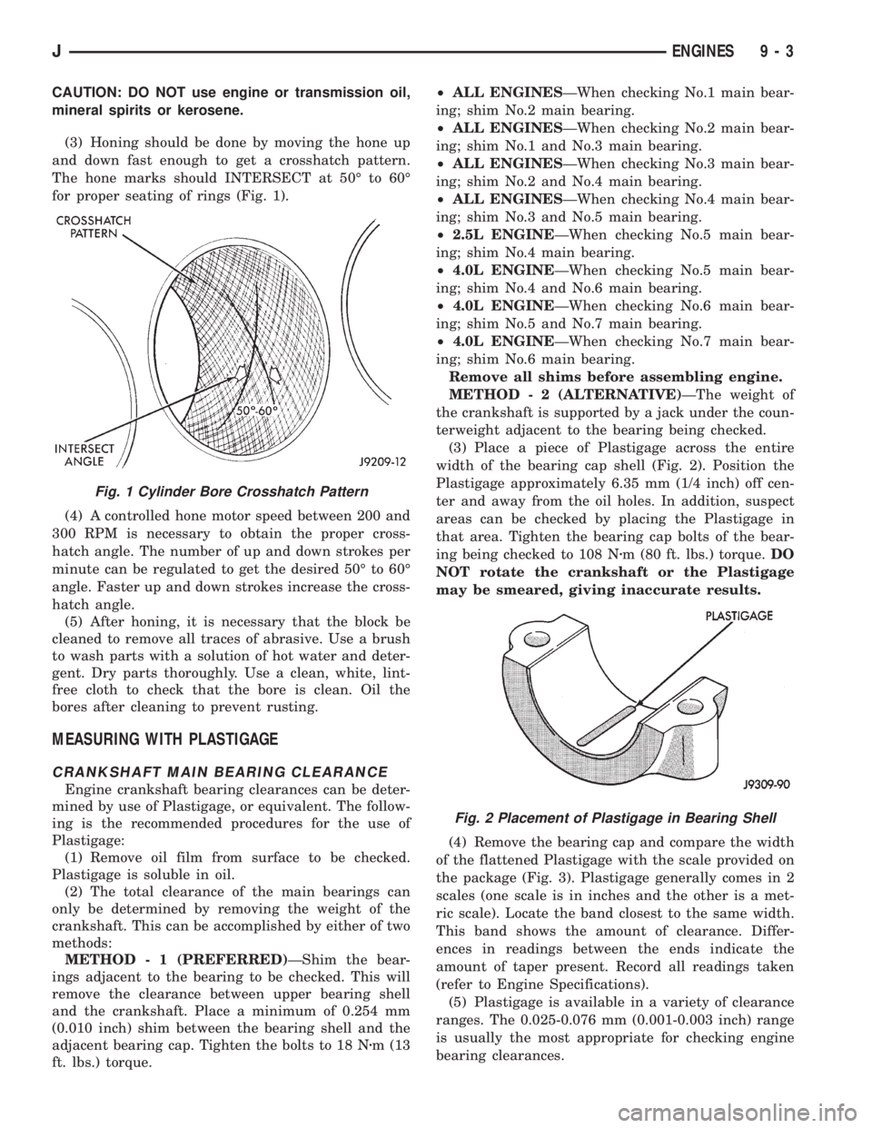
(3) Honing should be done by moving the hone up
and down fast enough to get a crosshatch pattern.
The hone marks should INTERSECT at 50É to 60É
for proper seating of rings (Fig. 1).
(4) A controlled hone motor speed between 200 and
300 RPM is necessary to obtain the proper cross-
hatch angle. The number of up and down strokes per
minute can be regulated to get the desired 50É to 60É
angle. Faster up and down strokes increase the cross-
hatch angle.
(5) After honing, it is necessary that the block be
cleaned to remove all traces of abrasive. Use a brush
to wash parts with a solution of hot water and deter-
gent. Dry parts thoroughly. Use a clean, white, lint-
free cloth to check that the bore is clean. Oil the
bores after cleaning to prevent rusting.
MEASURING WITH PLASTIGAGE
CRANKSHAFT MAIN BEARING CLEARANCE
Engine crankshaft bearing clearances can be deter-
mined by use of Plastigage, or equivalent. The follow-
ing is the recommended procedures for the use of
Plastigage:
(1) Remove oil film from surface to be checked.
Plastigage is soluble in oil.
(2) The total clearance of the main bearings can
only be determined by removing the weight of the
crankshaft. This can be accomplished by either of two
methods:
METHOD - 1 (PREFERRED)ÐShim the bear-
ings adjacent to the bearing to be checked. This will
remove the clearance between upper bearing shell
and the crankshaft. Place a minimum of 0.254 mm
(0.010 inch) shim between the bearing shell and the
adjacent bearing cap. Tighten the bolts to 18 Nzm (13
ft. lbs.) torque.²ALL ENGINESÐWhen checking No.1 main bear-
ing; shim No.2 main bearing.
²ALL ENGINESÐWhen checking No.2 main bear-
ing; shim No.1 and No.3 main bearing.
²ALL ENGINESÐWhen checking No.3 main bear-
ing; shim No.2 and No.4 main bearing.
²ALL ENGINESÐWhen checking No.4 main bear-
ing; shim No.3 and No.5 main bearing.
²2.5L ENGINEÐWhen checking No.5 main bear-
ing; shim No.4 main bearing.
²4.0L ENGINEÐWhen checking No.5 main bear-
ing; shim No.4 and No.6 main bearing.
²4.0L ENGINEÐWhen checking No.6 main bear-
ing; shim No.5 and No.7 main bearing.
²4.0L ENGINEÐWhen checking No.7 main bear-
ing; shim No.6 main bearing.
Remove all shims before assembling engine.
METHOD - 2 (ALTERNATIVE)ÐThe weight of
the crankshaft is supported by a jack under the coun-
terweight adjacent to the bearing being checked.
(3) Place a piece of Plastigage across the entire
width of the bearing cap shell (Fig. 2). Position the
Plastigage approximately 6.35 mm (1/4 inch) off cen-
ter and away from the oil holes. In addition, suspect
areas can be checked by placing the Plastigage in
that area. Tighten the bearing cap bolts of the bear-
ing being checked to 108 Nzm (80 ft. lbs.) torque.DO
NOT rotate the crankshaft or the Plastigage
may be smeared, giving inaccurate results.
(4) Remove the bearing cap and compare the width
of the flattened Plastigage with the scale provided on
the package (Fig. 3). Plastigage generally comes in 2
scales (one scale is in inches and the other is a met-
ric scale). Locate the band closest to the same width.
This band shows the amount of clearance. Differ-
ences in readings between the ends indicate the
amount of taper present. Record all readings taken
(refer to Engine Specifications).
(5) Plastigage is available in a variety of clearance
ranges. The 0.025-0.076 mm (0.001-0.003 inch) range
is usually the most appropriate for checking engine
bearing clearances.
Fig. 1 Cylinder Bore Crosshatch Pattern
Fig. 2 Placement of Plastigage in Bearing Shell
JENGINES 9 - 3
Page 1283 of 2158
CONNECTING ROD BEARING CLEARANCE
Engine connecting rod bearing clearances can be
determined by use of Plastigage, or equivalent. The
following is the recommended procedures for the use
of Plastigage:
(1) Remove oil film from surface to be checked.
Plastigage is soluble in oil.
(2) Place a piece of Plastigage across the entire width
of the bearing cap shell (Fig. 2). Position the Plastigage
approximately 6.35 mm (1/4 inch) off center and away
from the oil holes. In addition, suspect areas can be
checked by placing the Plastigage in the suspect area.
(3) The crankshaft must be turned until the connect-
ing rod to be checked starts moving toward the top of
the engine. Only then should the rod cap with Plasti-
gage in place be assembled. Tighten the rod cap nut to
45 Nzm (33 ft. lbs.) torque.DO NOT rotate the crank-
shaft or the Plastigage may be smeared, giving in-
accurate results.
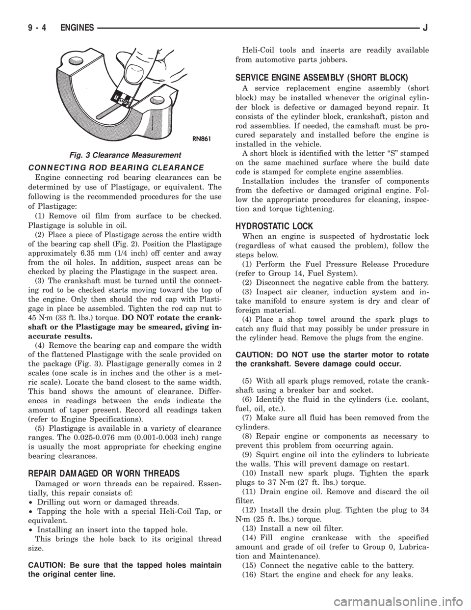
(4) Remove the bearing cap and compare the width
of the flattened Plastigage with the scale provided on
the package (Fig. 3). Plastigage generally comes in 2
scales (one scale is in inches and the other is a met-
ric scale). Locate the band closest to the same width.
This band shows the amount of clearance. Differ-
ences in readings between the ends indicate the
amount of taper present. Record all readings taken
(refer to Engine Specifications).
(5) Plastigage is available in a variety of clearance
ranges. The 0.025-0.076 mm (0.001-0.003 inch) range
is usually the most appropriate for checking engine
bearing clearances.
REPAIR DAMAGED OR WORN THREADS
Damaged or worn threads can be repaired. Essen-
tially, this repair consists of:
²Drilling out worn or damaged threads.
²Tapping the hole with a special Heli-Coil Tap, or
equivalent.
²Installing an insert into the tapped hole.
This brings the hole back to its original thread
size.
CAUTION: Be sure that the tapped holes maintain
the original center line.Heli-Coil tools and inserts are readily available
from automotive parts jobbers.
SERVICE ENGINE ASSEMBLY (SHORT BLOCK)
A service replacement engine assembly (short
block) may be installed whenever the original cylin-
der block is defective or damaged beyond repair. It
consists of the cylinder block, crankshaft, piston and
rod assemblies. If needed, the camshaft must be pro-
cured separately and installed before the engine is
installed in the vehicle.
A short block is identified with the letter ``S'' stamped
on the same machined surface where the build date
code is stamped for complete engine assemblies.
Installation includes the transfer of components
from the defective or damaged original engine. Fol-
low the appropriate procedures for cleaning, inspec-
tion and torque tightening.
HYDROSTATIC LOCK
When an engine is suspected of hydrostatic lock
(regardless of what caused the problem), follow the
steps below.
(1) Perform the Fuel Pressure Release Procedure
(refer to Group 14, Fuel System).
(2) Disconnect the negative cable from the battery.
(3) Inspect air cleaner, induction system and in-
take manifold to ensure system is dry and clear of
foreign material.
(4) Place a shop towel around the spark plugs to
catch any fluid that may possibly be under pressure in
the cylinder head. Remove the plugs from the engine.
CAUTION: DO NOT use the starter motor to rotate
the crankshaft. Severe damage could occur.
(5) With all spark plugs removed, rotate the crank-
shaft using a breaker bar and socket.
(6) Identify the fluid in the cylinders (i.e. coolant,
fuel, oil, etc.).
(7) Make sure all fluid has been removed from the
cylinders.
(8) Repair engine or components as necessary to
prevent this problem from occurring again.
(9) Squirt engine oil into the cylinders to lubricate
the walls. This will prevent damage on restart.
(10) Install new spark plugs. Tighten the spark
plugs to 37 Nzm (27 ft. lbs.) torque.
(11) Drain engine oil. Remove and discard the oil
filter.
(12) Install the drain plug. Tighten the plug to 34
Nzm (25 ft. lbs.) torque.
(13) Install a new oil filter.
(14) Fill engine crankcase with the specified
amount and grade of oil (refer to Group 0, Lubrica-
tion and Maintenance).
(15) Connect the negative cable to the battery.
(16) Start the engine and check for any leaks.
Fig. 3 Clearance Measurement
9 - 4 ENGINESJ
Page 1307 of 2158
(2) Use Valve Spring Compressor Tool
MD-998772A and compress each valve spring.
(3) Remove the valve locks, retainers, springs and
valve stem oil seals. Discard the oil seals.
(4) Use an Arkansas smooth stone or a jewelers
file to remove any burrs on the top of the valve stem,
especially around the groove for the locks.
(5) Remove the valves, and place them in a rack in
the same order as removed.
VALVE CLEANING
Clean all carbon deposits from the combustion
chambers, valve ports, valve stems, valve stem
guides and head.
Clean all grime and gasket material from the en-
gine cylinder head machined gasket surface.
INSPECTION
Inspect for cracks in the combustion chambers and
valve ports.
Inspect for cracks on the exhaust seat.
Inspect for cracks in the gasket surface at each
coolant passage.
Inspect valves for burned, cracked or warped
heads.
Inspect for scuffed or bent valve stems.
Replace valves displaying any damage.
VALVE REFACING
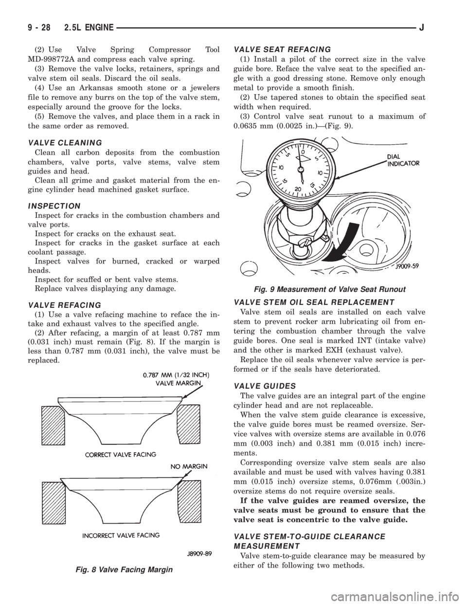
(1) Use a valve refacing machine to reface the in-
take and exhaust valves to the specified angle.
(2) After refacing, a margin of at least 0.787 mm
(0.031 inch) must remain (Fig. 8). If the margin is
less than 0.787 mm (0.031 inch), the valve must be
replaced.
VALVE SEAT REFACING
(1) Install a pilot of the correct size in the valve
guide bore. Reface the valve seat to the specified an-
gle with a good dressing stone. Remove only enough
metal to provide a smooth finish.
(2) Use tapered stones to obtain the specified seat
width when required.
(3) Control valve seat runout to a maximum of
0.0635 mm (0.0025 in.)Ð(Fig. 9).
VALVE STEM OIL SEAL REPLACEMENT
Valve stem oil seals are installed on each valve
stem to prevent rocker arm lubricating oil from en-
tering the combustion chamber through the valve
guide bores. One seal is marked INT (intake valve)
and the other is marked EXH (exhaust valve).
Replace the oil seals whenever valve service is per-
formed or if the seals have deteriorated.
VALVE GUIDES
The valve guides are an integral part of the engine
cylinder head and are not replaceable.
When the valve stem guide clearance is excessive,
the valve guide bores must be reamed oversize. Ser-
vice valves with oversize stems are available in 0.076
mm (0.003 inch) and 0.381 mm (0.015 inch) incre-
ments.
Corresponding oversize valve stem seals are also
available and must be used with valves having 0.381
mm (0.015 inch) oversize stems, 0.076mm (.003in.)
oversize stems do not require oversize seals.
If the valve guides are reamed oversize, the
valve seats must be ground to ensure that the
valve seat is concentric to the valve guide.
VALVE STEM-TO-GUIDE CLEARANCE
MEASUREMENT
Valve stem-to-guide clearance may be measured by
either of the following two methods.
Fig. 8 Valve Facing Margin
Fig. 9 Measurement of Valve Seat Runout
9 - 28 2.5L ENGINEJ
Page 1320 of 2158
(5) Install the lower bearing insert in the bearing
cap. The lower insert must be dry. Place strip of Plas-
tigage across full width of the lower insert at the cen-
ter of bearing cap. Plastigage must not crumble in
use. If brittle, obtain fresh stock.
(6) Install bearing cap and connecting rod on the
journal and tighten nuts to 45 Nzm (33 ft. lbs.)
torque. DO NOT rotate crankshaft. Plastigage will
smear, resulting in inaccurate indication.
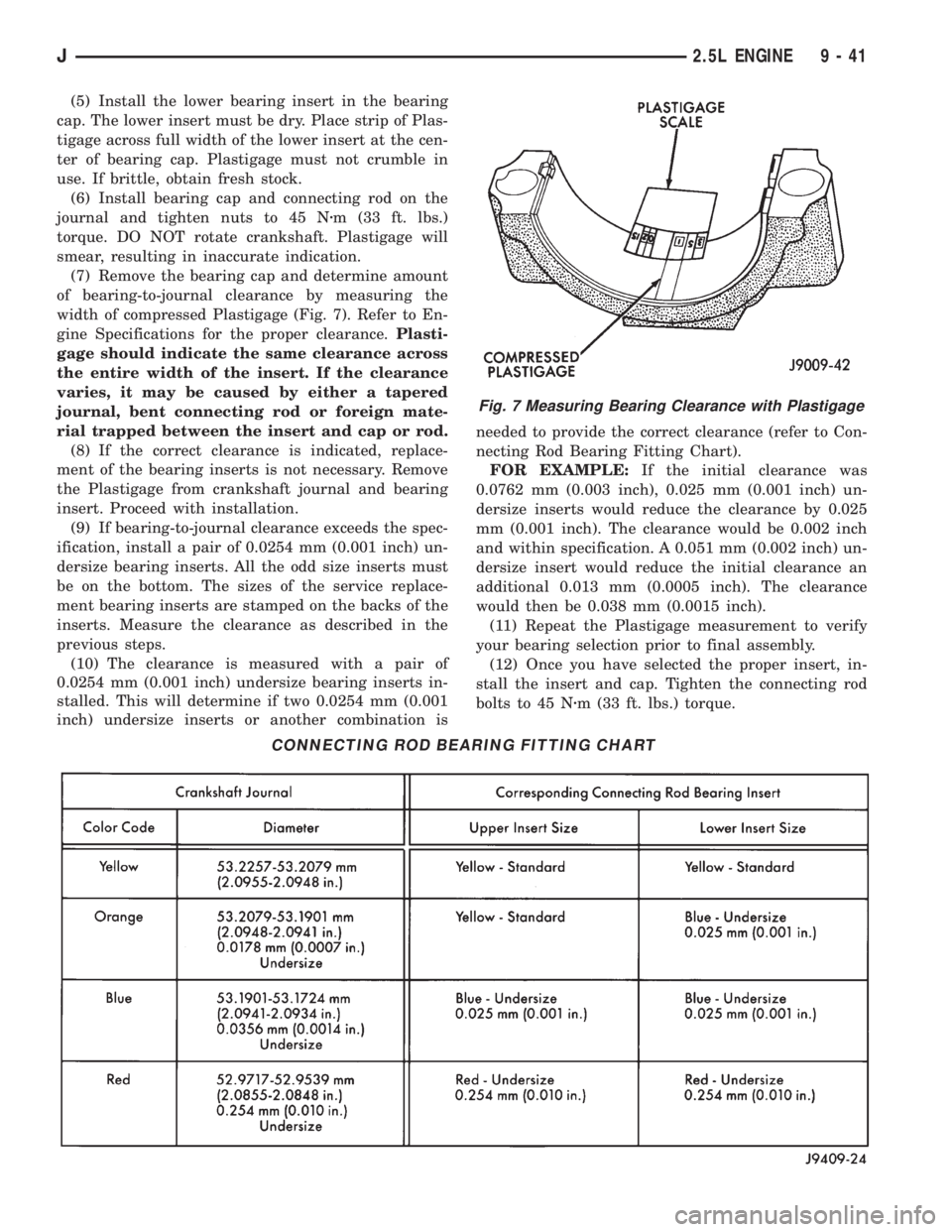
(7) Remove the bearing cap and determine amount
of bearing-to-journal clearance by measuring the
width of compressed Plastigage (Fig. 7). Refer to En-
gine Specifications for the proper clearance.Plasti-
gage should indicate the same clearance across
the entire width of the insert. If the clearance
varies, it may be caused by either a tapered
journal, bent connecting rod or foreign mate-
rial trapped between the insert and cap or rod.
(8) If the correct clearance is indicated, replace-
ment of the bearing inserts is not necessary. Remove
the Plastigage from crankshaft journal and bearing
insert. Proceed with installation.
(9) If bearing-to-journal clearance exceeds the spec-
ification, install a pair of 0.0254 mm (0.001 inch) un-
dersize bearing inserts. All the odd size inserts must
be on the bottom. The sizes of the service replace-
ment bearing inserts are stamped on the backs of the
inserts. Measure the clearance as described in the
previous steps.
(10) The clearance is measured with a pair of
0.0254 mm (0.001 inch) undersize bearing inserts in-
stalled. This will determine if two 0.0254 mm (0.001
inch) undersize inserts or another combination isneeded to provide the correct clearance (refer to Con-
necting Rod Bearing Fitting Chart).
FOR EXAMPLE:If the initial clearance was
0.0762 mm (0.003 inch), 0.025 mm (0.001 inch) un-
dersize inserts would reduce the clearance by 0.025
mm (0.001 inch). The clearance would be 0.002 inch
and within specification. A 0.051 mm (0.002 inch) un-
dersize insert would reduce the initial clearance an
additional 0.013 mm (0.0005 inch). The clearance
would then be 0.038 mm (0.0015 inch).
(11) Repeat the Plastigage measurement to verify
your bearing selection prior to final assembly.
(12) Once you have selected the proper insert, in-
stall the insert and cap. Tighten the connecting rod
bolts to 45 Nzm (33 ft. lbs.) torque.
Fig. 7 Measuring Bearing Clearance with Plastigage
CONNECTING ROD BEARING FITTING CHART
J2.5L ENGINE 9 - 41
Page 1325 of 2158
FITTING (CRANKSHAFT INSTALLED)
The main bearing caps, numbered (front to rear)
from 1 through 5 have an arrow to indicate the for-
ward position. The upper main bearing inserts are
grooved to provide oil channels while the lower in-
serts are smooth.
Each bearing insert pair is selectively fitted to its
respective journal to obtain the specified operating
clearance. In production, the select fit is obtained by
using various-sized color-coded bearing insert pairs
as listed in the Main Bearing Fitting Chart. The
bearing color code appears on the edge of the insert.
The size is not stamped on bearing inserts used
for engine production.
The main bearing journal size (diameter) is identi-
fied by a color-coded paint mark on the adjacent
cheek. The rear main journal, is identified by a color-
coded paint mark on the crankshaft rear flange.
When required, upper and lower bearing inserts of
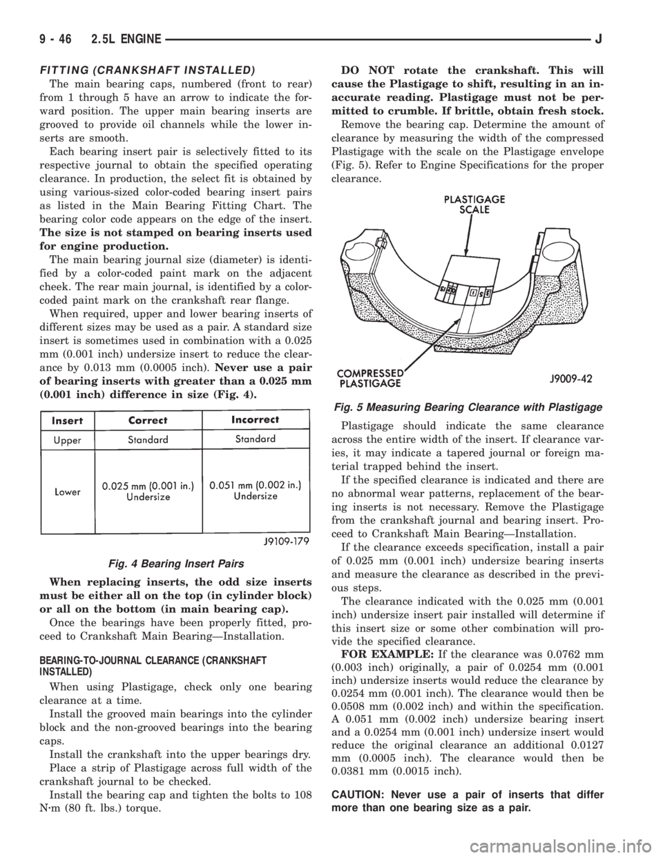
different sizes may be used as a pair. A standard size
insert is sometimes used in combination with a 0.025
mm (0.001 inch) undersize insert to reduce the clear-
ance by 0.013 mm (0.0005 inch).Never use a pair
of bearing inserts with greater than a 0.025 mm
(0.001 inch) difference in size (Fig. 4).
When replacing inserts, the odd size inserts
must be either all on the top (in cylinder block)
or all on the bottom (in main bearing cap).
Once the bearings have been properly fitted, pro-
ceed to Crankshaft Main BearingÐInstallation.
BEARING-TO-JOURNAL CLEARANCE (CRANKSHAFT
INSTALLED)
When using Plastigage, check only one bearing
clearance at a time.
Install the grooved main bearings into the cylinder
block and the non-grooved bearings into the bearing
caps.
Install the crankshaft into the upper bearings dry.
Place a strip of Plastigage across full width of the
crankshaft journal to be checked.
Install the bearing cap and tighten the bolts to 108
Nzm (80 ft. lbs.) torque.DO NOT rotate the crankshaft. This will
cause the Plastigage to shift, resulting in an in-
accurate reading. Plastigage must not be per-
mitted to crumble. If brittle, obtain fresh stock.
Remove the bearing cap. Determine the amount of
clearance by measuring the width of the compressed
Plastigage with the scale on the Plastigage envelope
(Fig. 5). Refer to Engine Specifications for the proper
clearance.
Plastigage should indicate the same clearance
across the entire width of the insert. If clearance var-
ies, it may indicate a tapered journal or foreign ma-
terial trapped behind the insert.
If the specified clearance is indicated and there are
no abnormal wear patterns, replacement of the bear-
ing inserts is not necessary. Remove the Plastigage
from the crankshaft journal and bearing insert. Pro-
ceed to Crankshaft Main BearingÐInstallation.
If the clearance exceeds specification, install a pair
of 0.025 mm (0.001 inch) undersize bearing inserts
and measure the clearance as described in the previ-
ous steps.
The clearance indicated with the 0.025 mm (0.001
inch) undersize insert pair installed will determine if
this insert size or some other combination will pro-
vide the specified clearance.
FOR EXAMPLE:If the clearance was 0.0762 mm
(0.003 inch) originally, a pair of 0.0254 mm (0.001
inch) undersize inserts would reduce the clearance by
0.0254 mm (0.001 inch). The clearance would then be
0.0508 mm (0.002 inch) and within the specification.
A 0.051 mm (0.002 inch) undersize bearing insert
and a 0.0254 mm (0.001 inch) undersize insert would
reduce the original clearance an additional 0.0127
mm (0.0005 inch). The clearance would then be
0.0381 mm (0.0015 inch).
CAUTION: Never use a pair of inserts that differ
more than one bearing size as a pair.
Fig. 4 Bearing Insert Pairs
Fig. 5 Measuring Bearing Clearance with Plastigage
9 - 46 2.5L ENGINEJ
Page 1349 of 2158
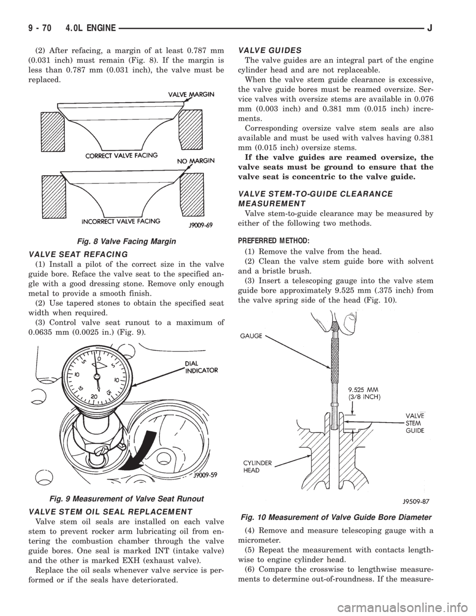
(2) After refacing, a margin of at least 0.787 mm
(0.031 inch) must remain (Fig. 8). If the margin is
less than 0.787 mm (0.031 inch), the valve must be
replaced.
VALVE SEAT REFACING
(1) Install a pilot of the correct size in the valve
guide bore. Reface the valve seat to the specified an-
gle with a good dressing stone. Remove only enough
metal to provide a smooth finish.
(2) Use tapered stones to obtain the specified seat
width when required.
(3) Control valve seat runout to a maximum of
0.0635 mm (0.0025 in.) (Fig. 9).
VALVE STEM OIL SEAL REPLACEMENT
Valve stem oil seals are installed on each valve
stem to prevent rocker arm lubricating oil from en-
tering the combustion chamber through the valve
guide bores. One seal is marked INT (intake valve)
and the other is marked EXH (exhaust valve).
Replace the oil seals whenever valve service is per-
formed or if the seals have deteriorated.
VALVE GUIDES
The valve guides are an integral part of the engine
cylinder head and are not replaceable.
When the valve stem guide clearance is excessive,
the valve guide bores must be reamed oversize. Ser-
vice valves with oversize stems are available in 0.076
mm (0.003 inch) and 0.381 mm (0.015 inch) incre-
ments.
Corresponding oversize valve stem seals are also
available and must be used with valves having 0.381
mm (0.015 inch) oversize stems.
If the valve guides are reamed oversize, the
valve seats must be ground to ensure that the
valve seat is concentric to the valve guide.
VALVE STEM-TO-GUIDE CLEARANCE
MEASUREMENT
Valve stem-to-guide clearance may be measured by
either of the following two methods.
PREFERRED METHOD:
(1) Remove the valve from the head.
(2) Clean the valve stem guide bore with solvent
and a bristle brush.
(3) Insert a telescoping gauge into the valve stem
guide bore approximately 9.525 mm (.375 inch) from
the valve spring side of the head (Fig. 10).
(4) Remove and measure telescoping gauge with a
micrometer.
(5) Repeat the measurement with contacts length-
wise to engine cylinder head.
(6) Compare the crosswise to lengthwise measure-
ments to determine out-of-roundness. If the measure-
Fig. 10 Measurement of Valve Guide Bore Diameter
Fig. 8 Valve Facing Margin
Fig. 9 Measurement of Valve Seat Runout
9 - 70 4.0L ENGINEJ
Page 1362 of 2158
(5) Install the lower bearing insert in the bearing
cap. The lower insert must be dry. Place strip of Plas-
tigage across full width of the lower insert at the cen-
ter of bearing cap. Plastigage must not crumble in
use. If brittle, obtain fresh stock.
(6) Install bearing cap and connecting rod on the
journal and tighten nuts to 45 Nzm (33 ft. lbs.)
torque. DO NOT rotate crankshaft. Plastigage will
smear, resulting in inaccurate indication.
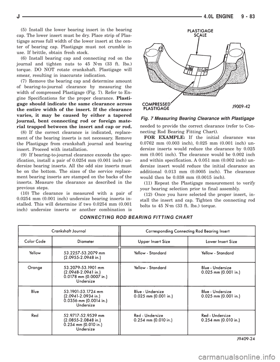
(7) Remove the bearing cap and determine amount
of bearing-to-journal clearance by measuring the
width of compressed Plastigage (Fig. 7). Refer to En-
gine Specifications for the proper clearance.Plasti-
gage should indicate the same clearance across
the entire width of the insert. If the clearance
varies, it may be caused by either a tapered
journal, bent connecting rod or foreign mate-
rial trapped between the insert and cap or rod.
(8) If the correct clearance is indicated, replace-
ment of the bearing inserts is not necessary. Remove
the Plastigage from crankshaft journal and bearing
insert. Proceed with installation.
(9) If bearing-to-journal clearance exceeds the spec-
ification, install a pair of 0.0254 mm (0.001 inch) un-
dersize bearing inserts. All the odd size inserts must
be on the bottom. The sizes of the service replace-
ment bearing inserts are stamped on the backs of the
inserts. Measure the clearance as described in the
previous steps.
(10) The clearance is measured with a pair of
0.0254 mm (0.001 inch) undersize bearing inserts in-
stalled. This will determine if two 0.0254 mm (0.001
inch) undersize inserts or another combination isneeded to provide the correct clearance (refer to Con-
necting Rod Bearing Fitting Chart).
FOR EXAMPLE:If the initial clearance was
0.0762 mm (0.003 inch), 0.025 mm (0.001 inch) un-
dersize inserts would reduce the clearance by 0.025
mm (0.001 inch). The clearance would be 0.002 inch
and within specification. A 0.051 mm (0.002 inch) un-
dersize insert would reduce the initial clearance an
additional 0.013 mm (0.0005 inch). The clearance
would then be 0.038 mm (0.0015 inch).
(11) Repeat the Plastigage measurement to verify
your bearing selection prior to final assembly.
(12) Once you have selected the proper insert, in-
stall the insert and cap. Tighten the connecting rod
bolts to 45 Nzm (33 ft. lbs.) torque.
Fig. 7 Measuring Bearing Clearance with Plastigage
CONNECTING ROD BEARING FITTING CHART
J4.0L ENGINE 9 - 83