Page 1993 of 2158
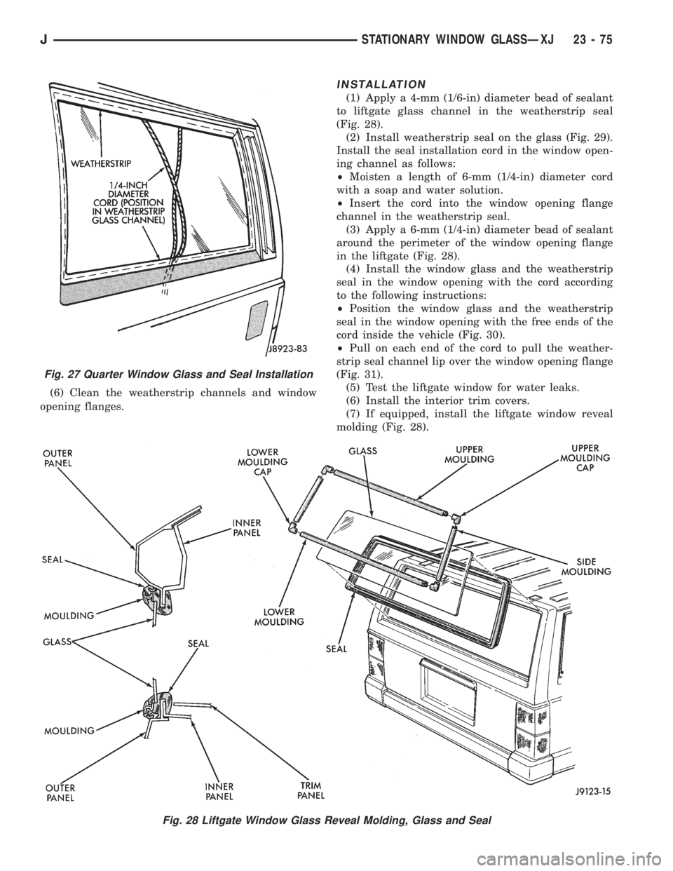
(6) Clean the weatherstrip channels and window
opening flanges.
INSTALLATION
(1) Apply a 4-mm (1/6-in) diameter bead of sealant
to liftgate glass channel in the weatherstrip seal
(Fig. 28).
(2) Install weatherstrip seal on the glass (Fig. 29).
Install the seal installation cord in the window open-
ing channel as follows:
²Moisten a length of 6-mm (1/4-in) diameter cord
with a soap and water solution.
²Insert the cord into the window opening flange
channel in the weatherstrip seal.
(3) Apply a 6-mm (1/4-in) diameter bead of sealant
around the perimeter of the window opening flange
in the liftgate (Fig. 28).
(4) Install the window glass and the weatherstrip
seal in the window opening with the cord according
to the following instructions:
²Position the window glass and the weatherstrip
seal in the window opening with the free ends of the
cord inside the vehicle (Fig. 30).
²Pull on each end of the cord to pull the weather-
strip seal channel lip over the window opening flange
(Fig. 31).
(5) Test the liftgate window for water leaks.
(6) Install the interior trim covers.
(7) If equipped, install the liftgate window reveal
molding (Fig. 28).
Fig. 28 Liftgate Window Glass Reveal Molding, Glass and Seal
Fig. 27 Quarter Window Glass and Seal Installation
JSTATIONARY WINDOW GLASSÐXJ 23 - 75
Page 2016 of 2158
SPARE TIRE/WHEEL HOLDDOWN AND FLOOR
BRACKETSÐXJ
REMOVAL
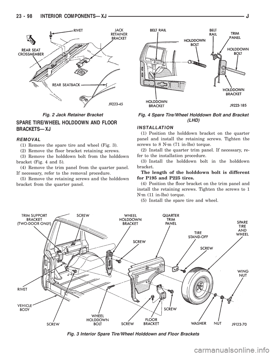
(1) Remove the spare tire and wheel (Fig. 3).
(2) Remove the floor bracket retaining screws.
(3) Remove the holddown bolt from the holddown
bracket (Fig. 4 and 5).
(4) Remove the trim panel from the quarter panel.
If necessary, refer to the removal procedure.
(5) Remove the retaining screws and the holddown
bracket from the quarter panel.
INSTALLATION
(1) Position the holddown bracket on the quarter
panel and install the retaining screws. Tighten the
screws to 8 Nzm (71 in-lbs) torque.
(2) Install the quarter trim panel. If necessary, re-
fer to the installation procedure.
(3) Install the holddown bolt in the holddown
bracket.
The length of the holddown bolt is different
for P195 and P225 tires.
(4) Position the floor bracket on the trim panel and
install the retaining screws. Tighten the screws to 1
Nzm (11 in-lbs) torque.
(5) Install the spare tire and wheel.
Fig. 3 Interior Spare Tire/Wheel Holddown and Floor Brackets
Fig. 2 Jack Retainer BracketFig. 4 Spare Tire/Wheel Holddown Bolt and Bracket
(LHD)
23 - 98 INTERIOR COMPONENTSÐXJJ
Page 2035 of 2158
The work area temperature should be between
18ÉC (65ÉF) and 32ÉC (90ÉF).A tape stripe/decal
should not be replaced if the work area temper-
ature is less than 18ÉC (65ÉF).
The following equipment and material are neces-
sary for body stripe/decal removal and installation:
²Commercial tape stripe/decal removal solution.
²Commercial adhesive removal solution.
²Liquid dish detergent (for the wetting solution).
²Mixture of wetting solution.
²Commercial wax and silicone removal solution.
²Isopropyl (rubbing) alcohol.
²Small squeegee (plastic or hard rubber).
²Water bucket and sponge.
²Clean wiping rags or paper towels.
²Heat gun (or infra-red heat bulb).
²Wax pencil.
²Sharp knife, single edge razor blade or X-acto
knife.
²Pair of scissors.
²Needle or pin.
A wetting solution assures a better bond between
the painted surface of the body and the tape stripe/
decal. Prepare a supply of wetting solution by mixing
two or three teaspoons of dish detergent with 1 gal-
lon of water.Do not use soap.
Too much detergent will reduce the effective-
ness of the mixture.
REMOVAL
The key to successful tape stripe/decal re-
moval is to apply heat to area and slowly peel
stripe/decal from panel.
(1) Clean the repaired surface, adjacent panels and
door openings as necessary.
(2) Start at one end of the tape stripe/decal and
apply heat with a heat gun. Slowly peel the stripe/
decal from the panel by pulling it back.Do not pull
the tape stripe/decal outward from the panel.
WARNING: USE THE TAPE STRIPE/DECAL RE-
MOVAL SOLUTION IN A WELL-VENTILATED AREA
ONLY.
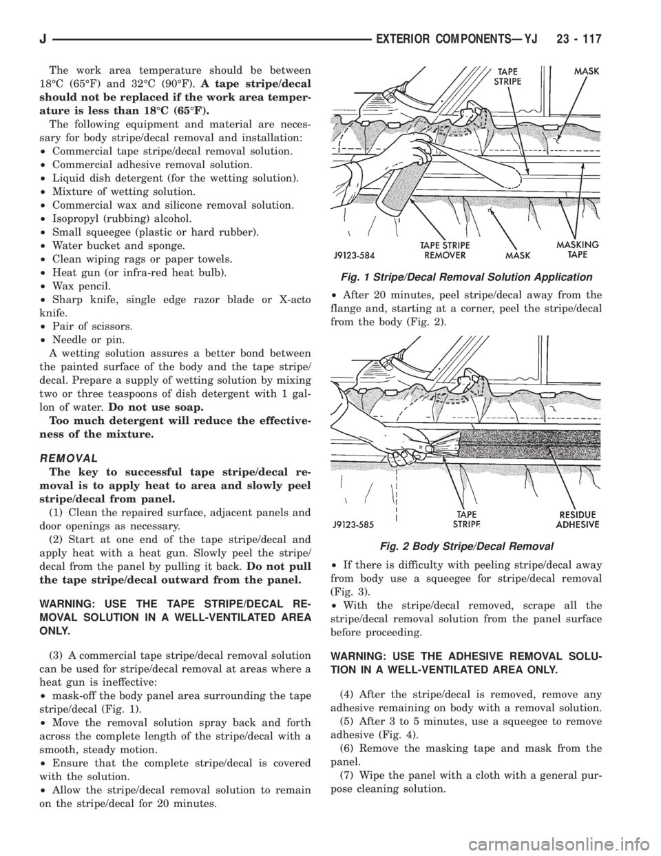
(3) A commercial tape stripe/decal removal solution
can be used for stripe/decal removal at areas where a
heat gun is ineffective:
²mask-off the body panel area surrounding the tape
stripe/decal (Fig. 1).
²Move the removal solution spray back and forth
across the complete length of the stripe/decal with a
smooth, steady motion.
²Ensure that the complete stripe/decal is covered
with the solution.
²Allow the stripe/decal removal solution to remain
on the stripe/decal for 20 minutes.²After 20 minutes, peel stripe/decal away from the
flange and, starting at a corner, peel the stripe/decal
from the body (Fig. 2).
²If there is difficulty with peeling stripe/decal away
from body use a squeegee for stripe/decal removal
(Fig. 3).
²With the stripe/decal removed, scrape all the
stripe/decal removal solution from the panel surface
before proceeding.
WARNING: USE THE ADHESIVE REMOVAL SOLU-
TION IN A WELL-VENTILATED AREA ONLY.
(4) After the stripe/decal is removed, remove any
adhesive remaining on body with a removal solution.
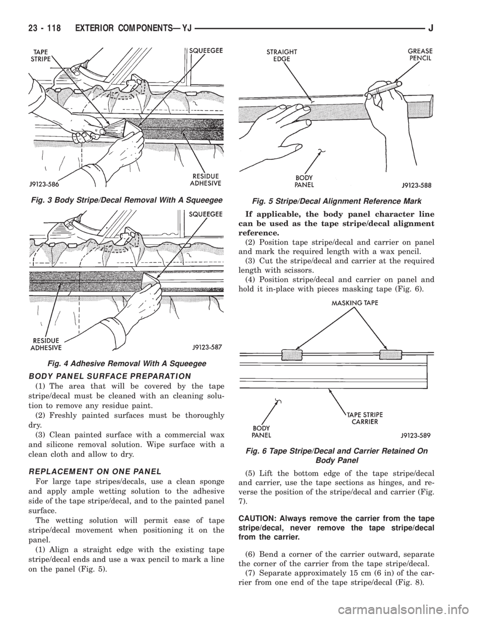
(5) After 3 to 5 minutes, use a squeegee to remove
adhesive (Fig. 4).
(6) Remove the masking tape and mask from the
panel.
(7) Wipe the panel with a cloth with a general pur-
pose cleaning solution.
Fig. 1 Stripe/Decal Removal Solution Application
Fig. 2 Body Stripe/Decal Removal
JEXTERIOR COMPONENTSÐYJ 23 - 117
Page 2036 of 2158
BODY PANEL SURFACE PREPARATION
(1) The area that will be covered by the tape
stripe/decal must be cleaned with an cleaning solu-
tion to remove any residue paint.
(2) Freshly painted surfaces must be thoroughly
dry.
(3) Clean painted surface with a commercial wax
and silicone removal solution. Wipe surface with a
clean cloth and allow to dry.
REPLACEMENT ON ONE PANEL
For large tape stripes/decals, use a clean sponge
and apply ample wetting solution to the adhesive
side of the tape stripe/decal, and to the painted panel
surface.
The wetting solution will permit ease of tape
stripe/decal movement when positioning it on the
panel.
(1) Align a straight edge with the existing tape
stripe/decal ends and use a wax pencil to mark a line
on the panel (Fig. 5).If applicable, the body panel character line
can be used as the tape stripe/decal alignment
reference.
(2) Position tape stripe/decal and carrier on panel
and mark the required length with a wax pencil.
(3) Cut the stripe/decal and carrier at the required
length with scissors.
(4) Position stripe/decal and carrier on panel and
hold it in-place with pieces masking tape (Fig. 6).
(5) Lift the bottom edge of the tape stripe/decal
and carrier, use the tape sections as hinges, and re-
verse the position of the stripe/decal and carrier (Fig.
7).
CAUTION: Always remove the carrier from the tape
stripe/decal, never remove the tape stripe/decal
from the carrier.
(6) Bend a corner of the carrier outward, separate
the corner of the carrier from the tape stripe/decal.
(7) Separate approximately 15 cm (6 in) of the car-
rier from one end of the tape stripe/decal (Fig. 8).
Fig. 3 Body Stripe/Decal Removal With A Squeegee
Fig. 4 Adhesive Removal With A Squeegee
Fig. 5 Stripe/Decal Alignment Reference Mark
Fig. 6 Tape Stripe/Decal and Carrier Retained On
Body Panel
23 - 118 EXTERIOR COMPONENTSÐYJJ
Page 2061 of 2158
(2) Position the door at the body opening, insert
the hinge pins in the hinge receptacles and install
the retaining nuts (Fig. 16). Tighten the nuts se-
curely.
(3) Install the weatherstrip seal on the door edge
(Fig. 18).
(4) Install the door outside handle and the keepers.
Connect the latch release rod to the handle (Fig. 13).
(5) Install the key lock cylinder (Fig. 14).
(6) Position the window glass in the channel and
the door.
(7) Attach the window glass to the regulator arm
guide (Fig. 12).
(8) Install the beltline weatherstrip seals in the
door (Fig. 18).
(9) Position the latch in the door and install the re-
taining screws (Fig. 15). Tighten the screws securely.
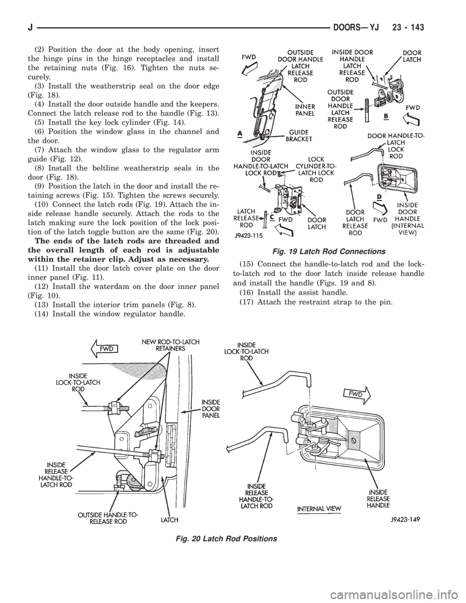
(10) Connect the latch rods (Fig. 19). Attach the in-
side release handle securely. Attach the rods to the
latch making sure the lock position of the lock posi-
tion of the latch toggle button are the same (Fig. 20).
The ends of the latch rods are threaded and
the overall length of each rod is adjustable
within the retainer clip. Adjust as necessary.
(11) Install the door latch cover plate on the door
inner panel (Fig. 11).
(12) Install the waterdam on the door inner panel
(Fig. 10).
(13) Install the interior trim panels (Fig. 8).
(14) Install the window regulator handle.(15) Connect the handle-to-latch rod and the lock-
to-latch rod to the door latch inside release handle
and install the handle (Figs. 19 and 8).
(16) Install the assist handle.
(17) Attach the restraint strap to the pin.
Fig. 19 Latch Rod Connections
Fig. 20 Latch Rod Positions
JDOORSÐYJ 23 - 143