1995 JEEP YJ timing belt
[x] Cancel search: timing beltPage 244 of 2158
EXAMPLES:
²If the lamp (Figs. 5 or 6) flashes 1 time, pauses
and flashes 2 more times, a flashing Diagnostic Trou-
ble Code (DTC) number 12 is indicated. If this code is
observed, it is indicating that the battery has been
disconnected within the last 50 key-on cycles. It
could also indicate that battery voltage has been dis-
connected to the PCM. In either case, other DTC's
may have been erased.
²If the lamp flashes 1 time, pauses and flashes 7
more times, a flashing Diagnostic Trouble Code
(DTC) number 17 is indicated.
²If the lamp flashes 3 times, pauses and flashes 5
more times, a flashing Diagnostic Trouble Code
(DTC) number 35 is indicated.
After any stored DTC information has been ob-
served, the display will end with a flashing DTC
number 55. This will indicate the end of all stored in-
formation.
ERASING TROUBLE CODES
After the problem has been repaired, the DRB scan
tool must be used to erase a DTC. Refer to the ap-
propriate Powertrain Diagnostic Procedures service
manual for operation of the DRB scan tool.
DRB SCAN TOOL
For operation of the DRB scan tool, refer to the ap-
propriate Powertrain Diagnostic Procedures service
manual.
PRELIMINARY CHECKS
ENGINE COOLING SYSTEM OVERHEATING
Establish what driving conditions caused the com-
plaint. Abnormal loads on the cooling system such as
the following may be the cause.
1. PROLONGED IDLE, VERY HIGH AMBIENT
TEMPERATURE, SLIGHT TAIL WIND AT IDLE,
SLOW TRAFFIC, TRAFFIC JAMS, HIGH
SPEED, OR STEEP GRADES:
Driving techniques that avoid overheating are:
²Idle with A/C off when temperature gauge is at
end of normal range.
²Increasing engine speed for more air flow is recom-
mended.
2. TRAILER TOWING:
Consult Trailer Towing section of owners manual.
Do not exceed limits.
3. AIR CONDITIONING; ADD-ON OR AFTER
MARKET:
A maximum cooling package should have been or-
dered with vehicle if add-on or after market A/C is
installed. If not, maximum cooling system compo-
nents should be installed for model involved per
manufacturer's specifications.
4. RECENT SERVICE OR ACCIDENT REPAIR:
Determine if any recent service has been performed
on vehicle that may effect cooling system. This may
be:
²Engine adjustments (incorrect timing)
²Slipping engine accessory drive belt(s)
²Brakes (possibly dragging)
²Changed parts (incorrect water pump rotating in
wrong direction)
²Reconditioned radiator or cooling system refilling
(possibly under-filled or air trapped in system).
If investigation reveals none of the previous
items as a cause for an engine overheating com-
plaint, refer to following Cooling System Diag-
nosis charts.
These charts are to be used as a quick-reference
only. Refer to the group text for information.
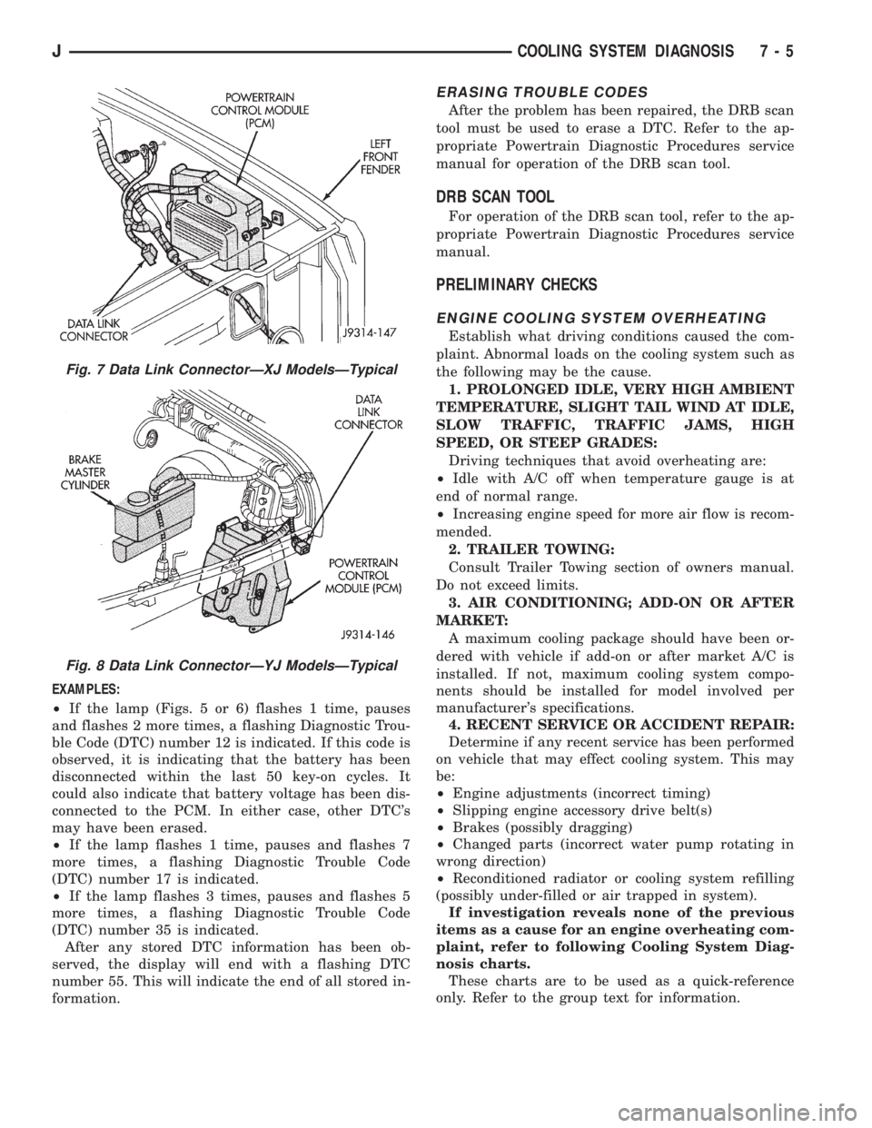
Fig. 7 Data Link ConnectorÐXJ ModelsÐTypical
Fig. 8 Data Link ConnectorÐYJ ModelsÐTypical
JCOOLING SYSTEM DIAGNOSIS 7 - 5
Page 273 of 2158
VISCOUS FAN DRIVE
DESCRIPTION AND OPERATION
Also refer to the previous section on Cooling Sys-
tem Fans.
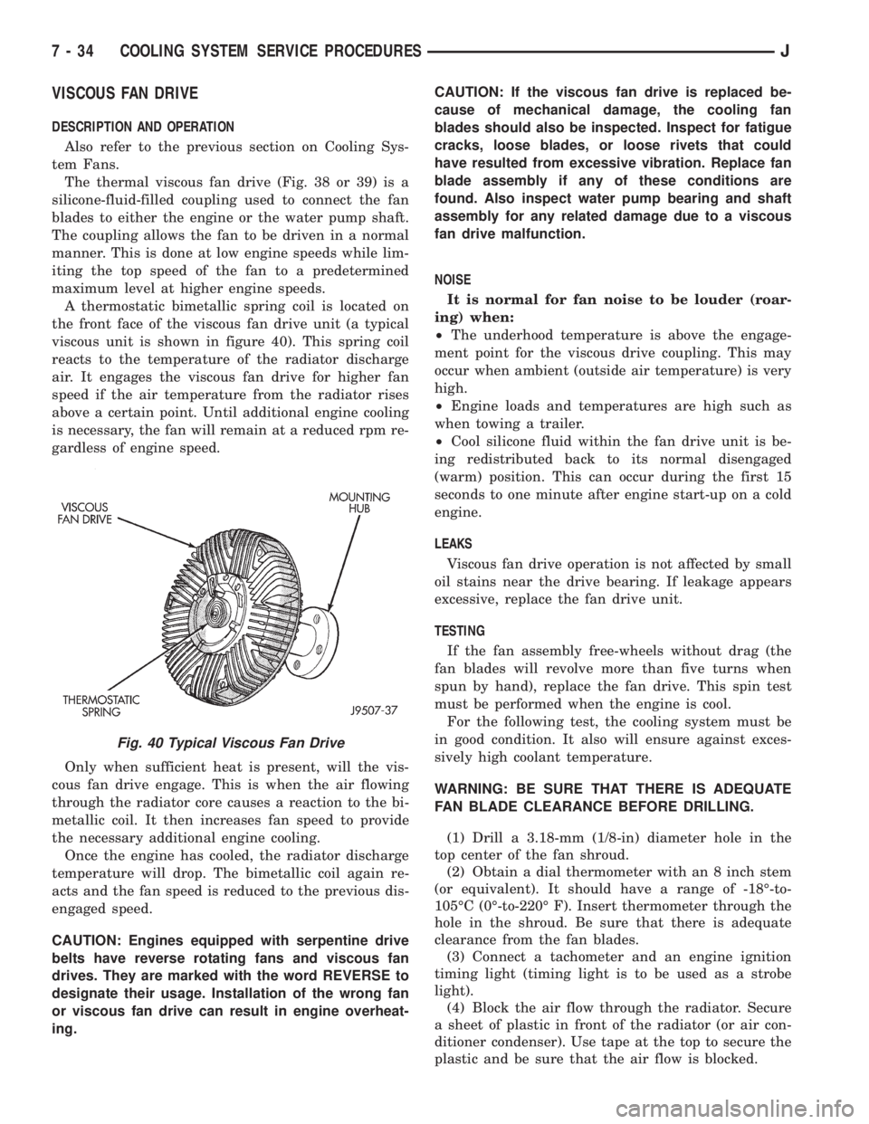
The thermal viscous fan drive (Fig. 38 or 39) is a
silicone-fluid-filled coupling used to connect the fan
blades to either the engine or the water pump shaft.
The coupling allows the fan to be driven in a normal
manner. This is done at low engine speeds while lim-
iting the top speed of the fan to a predetermined
maximum level at higher engine speeds.
A thermostatic bimetallic spring coil is located on
the front face of the viscous fan drive unit (a typical
viscous unit is shown in figure 40). This spring coil
reacts to the temperature of the radiator discharge
air. It engages the viscous fan drive for higher fan
speed if the air temperature from the radiator rises
above a certain point. Until additional engine cooling
is necessary, the fan will remain at a reduced rpm re-
gardless of engine speed.
Only when sufficient heat is present, will the vis-
cous fan drive engage. This is when the air flowing
through the radiator core causes a reaction to the bi-
metallic coil. It then increases fan speed to provide
the necessary additional engine cooling.
Once the engine has cooled, the radiator discharge
temperature will drop. The bimetallic coil again re-
acts and the fan speed is reduced to the previous dis-
engaged speed.
CAUTION: Engines equipped with serpentine drive
belts have reverse rotating fans and viscous fan
drives. They are marked with the word REVERSE to
designate their usage. Installation of the wrong fan
or viscous fan drive can result in engine overheat-
ing.CAUTION: If the viscous fan drive is replaced be-
cause of mechanical damage, the cooling fan
blades should also be inspected. Inspect for fatigue
cracks, loose blades, or loose rivets that could
have resulted from excessive vibration. Replace fan
blade assembly if any of these conditions are
found. Also inspect water pump bearing and shaft
assembly for any related damage due to a viscous
fan drive malfunction.
NOISE
It is normal for fan noise to be louder (roar-
ing) when:
²The underhood temperature is above the engage-
ment point for the viscous drive coupling. This may
occur when ambient (outside air temperature) is very
high.
²Engine loads and temperatures are high such as
when towing a trailer.
²Cool silicone fluid within the fan drive unit is be-
ing redistributed back to its normal disengaged
(warm) position. This can occur during the first 15
seconds to one minute after engine start-up on a cold
engine.
LEAKS
Viscous fan drive operation is not affected by small
oil stains near the drive bearing. If leakage appears
excessive, replace the fan drive unit.
TESTING
If the fan assembly free-wheels without drag (the
fan blades will revolve more than five turns when
spun by hand), replace the fan drive. This spin test
must be performed when the engine is cool.
For the following test, the cooling system must be
in good condition. It also will ensure against exces-
sively high coolant temperature.
WARNING: BE SURE THAT THERE IS ADEQUATE
FAN BLADE CLEARANCE BEFORE DRILLING.
(1) Drill a 3.18-mm (1/8-in) diameter hole in the
top center of the fan shroud.
(2) Obtain a dial thermometer with an 8 inch stem
(or equivalent). It should have a range of -18É-to-
105ÉC (0É-to-220É F). Insert thermometer through the
hole in the shroud. Be sure that there is adequate
clearance from the fan blades.
(3) Connect a tachometer and an engine ignition
timing light (timing light is to be used as a strobe
light).
(4) Block the air flow through the radiator. Secure
a sheet of plastic in front of the radiator (or air con-
ditioner condenser). Use tape at the top to secure the
plastic and be sure that the air flow is blocked.
Fig. 40 Typical Viscous Fan Drive
7 - 34 COOLING SYSTEM SERVICE PROCEDURESJ
Page 274 of 2158

(5) Be sure that the air conditioner (if equipped) is
turned off.
WARNING: USE EXTREME CAUTION WHEN THE
ENGINE IS OPERATING. DO NOT STAND IN A DI-
RECT LINE WITH THE FAN. DO NOT PUT YOUR
HANDS NEAR THE PULLEYS, BELTS OR FAN. DO
NOT WEAR LOOSE CLOTHING.
(6) Start the engine and operate at 2400 rpm.
Within ten minutes the air temperature (indicated on
the dial thermometer) should be up to 88É C (190É F).
Fan driveengagementshould have started to occur
at between 74É to 82É C (165É to 180É F). Engage-
ment is distinguishable by a definiteincreasein fan
flow noise (roaring). The timing light also will indi-
cate an increase in the speed of the fan.
(7) When the air temperature reaches 88É C (190É
F), remove the plastic sheet. Fan drivedisengage-
mentshould have started to occur at between 57É to
79É C (135É to 175É F). A definitedecreaseof fan
flow noise (roaring) should be noticed. If not, replace
the defective viscous fan drive unit.
VISCOUS FAN DRIVE REMOVAL/INSTALLATION
Refer to the previous section on Cooling System
Fan for removal and installation procedures of the
viscous drive unit.
Viscous Fan Drive Fluid Pump Out Require-
ment:After installing anewviscous fan drive, bring
the engine speed up to approximately 2000 rpm and
hold for approximately two minutes. This will ensure
proper fluid distribution within the drive.
AUXILIARY ELECTRIC COOLING FANÐXJ MODELS
WITH 4.0L 6-CYLINDER ENGINE
OPERATION
XJ models equipped with a 4.0L 6-cylinder engine
may also have an auxiliary electrical cooling fan.
This is with models that have air conditioning and/or
heavy duty cooling. The fan is controlled by the cool-
ing fan relay, which is located in the power distribu-
tion center (PDC). For the location of relay within
the PDC (Fig. 41), refer to the label on PDC cover.
When coolant temperature is above 88ÉC (190ÉF),
the powertrain control module (PCM) provides a
ground path for the fan relay. This ground is pro-
vided through pin/connector #31 of the PCM 60-way
connector. Battery voltage is then applied to the fan
through the relay. When coolant temperature is be-
low 88ÉC (190ÉF), the PCM opens the ground path to
the relay. This will prevent the cooling fan from be-
ing energized.
Whenever the air conditioning is operated, the
PCM engages the auxiliary cooling fan. It provides aground path to the cooling fan relay. This ground is
provided through pin/connector #31 of the PCM 60-
way connector.
DIAGNOSIS AND RELAY TESTING
The powertrain control module (PCM) will enter a
diagnostic trouble code (DTC) number 35 in memory
if it detects a problem in the auxiliary cooling fan re-
lay or circuit. This will be read as a flashing signal
at the instrument panel mounted Malfunction Indica-
tor Lamp (displayed on the instrument panel as the
CHECK ENGINE lampÐfigure 42). Refer to On-
Board Diagnostics in Group 14, Fuel Systems for in-
formation on accessing a DTC.
The DTC can also be accessed through the DRB
scan tool. Refer to the appropriate Powertrain Diag-
Fig. 41 PDCÐXJ Models
Fig. 42 Check Engine LampÐXJ ModelsÐTypical
JCOOLING SYSTEM SERVICE PROCEDURES 7 - 35
Page 1309 of 2158
at the engine cylinder head. Also tap the top of the
retainer to seat the valve locks.
(8) Install the engine cylinder head.
VALVE TIMING
Disconnect the spark plug wires and remove the
spark plugs.
Remove the engine cylinder head cover.
Remove the capscrews, bridge and pivot assembly,
and rocker arms from above the No.1 cylinder.
Alternately loosen each capscrew, one turn at a
time, to avoid damaging the bridge.
Rotate the crankshaft until the No.4 piston is at
top dead center (TDC) on the compression stroke.
Rotate the crankshaft counterclockwise (viewed
from the front of the engine) 90É.
Install a dial indicator on the end of the No.1 cyl-
inder intake valve push rod. Use rubber tubing to se-
cure the indicator stem on the push rod.
Set the dial indicator pointer at zero.
Rotate the crankshaft clockwise (viewed from the
front of the engine) until the dial indicator pointer
indicates 0.305 mm (0.012 inch) travel distance (lift).
The timing notch index on the vibration damper
should be aligned with the TDC mark on the timing
degree scale.
If the timing notch is more than 13 mm (1/2 inch)
away from the TDC mark in either direction, the
valve timing is incorrect.
If the valve timing is incorrect, the cause may be a
broken camshaft pin. It is not necessary to replace
the camshaft because of pin failure. A spring pin is
available for service replacement.
VIBRATION DAMPER
REMOVAL
(1) Disconnect negative cable from battery.
(2) Remove the serpentine drive belt and fan
shroud.
(3) Remove the vibration damper retaining bolt
and washer.
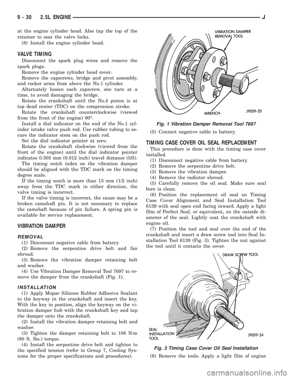
(4) Use Vibration Damper Removal Tool 7697 to re-
move the damper from the crankshaft (Fig. 1).
INSTALLATION
(1) Apply Mopar Silicone Rubber Adhesive Sealant
to the keyway in the crankshaft and insert the key.
With the key in position, align the keyway on the vi-
bration damper hub with the crankshaft key and tap
the damper onto the crankshaft.
(2) Install the vibration damper retaining bolt and
washer.
(3) Tighten the damper retaining bolt to 108 Nzm
(80 ft. lbs.) torque.
(4) Install the serpentine drive belt and tighten to
the specified tension (refer to Group 7, Cooling Sys-
tems for the proper specifications and procedures).(5) Connect negative cable to battery.
TIMING CASE COVER OIL SEAL REPLACEMENT
This procedure is done with the timing case cover
installed.
(1) Disconnect negative cable from battery.
(2) Remove the serpentine drive belt.
(3) Remove the vibration damper.
(4) Remove the radiator shroud.
(5) Carefully remove the oil seal. Make sure seal
bore is clean.
(6) Position the replacement oil seal on Timing
Case Cover Alignment and Seal Installation Tool
6139 with seal open end facing inward. Apply a light
film of Perfect Seal, or equivalent, on the outside di-
ameter of the seal. Lightly coat the crankshaft with
engine oil.
(7) Position the tool and seal over the end of the
crankshaft and insert a draw screw tool into Seal In-
stallation Tool 6139 (Fig. 3). Tighten the nut against
the tool until it contacts the cover.
(8) Remove the tools. Apply a light film of engine
Fig. 1 Vibration Damper Removal Tool 7697
Fig. 3 Timing Case Cover Oil Seal Installation
9 - 30 2.5L ENGINEJ
Page 1310 of 2158
oil on the vibration damper hub contact surface of
the seal.
(9) Apply Mopar Silicone Rubber Adhesive Sealant
to the keyway in the crankshaft and insert the key.
With the key inserted in the keyway in the crank-
shaft, install the vibration damper, washer and bolt.
Lubricate and tighten the bolt to 108 Nzm (80 ft. lbs.)
torque.
(10) Install the serpentine belt and tighten to the
specified tension (refer to Group 7, Cooling Systems
for the proper specifications and procedures).
(11) Install the radiator shroud.
(12) Connect negative cable to battery.
TIMING CASE COVER
REMOVAL
(1) Disconnect negative cable from battery.
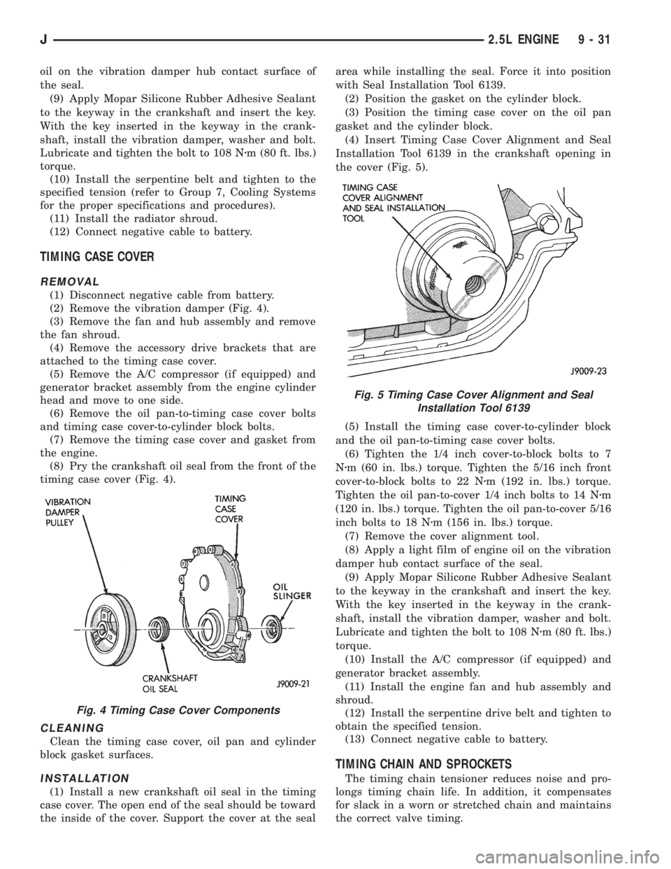
(2) Remove the vibration damper (Fig. 4).
(3) Remove the fan and hub assembly and remove
the fan shroud.
(4) Remove the accessory drive brackets that are
attached to the timing case cover.
(5) Remove the A/C compressor (if equipped) and
generator bracket assembly from the engine cylinder
head and move to one side.
(6) Remove the oil pan-to-timing case cover bolts
and timing case cover-to-cylinder block bolts.
(7) Remove the timing case cover and gasket from
the engine.
(8) Pry the crankshaft oil seal from the front of the
timing case cover (Fig. 4).
CLEANING
Clean the timing case cover, oil pan and cylinder
block gasket surfaces.
INSTALLATION
(1) Install a new crankshaft oil seal in the timing
case cover. The open end of the seal should be toward
the inside of the cover. Support the cover at the sealarea while installing the seal. Force it into position
with Seal Installation Tool 6139.
(2) Position the gasket on the cylinder block.
(3) Position the timing case cover on the oil pan
gasket and the cylinder block.
(4) Insert Timing Case Cover Alignment and Seal
Installation Tool 6139 in the crankshaft opening in
the cover (Fig. 5).
(5) Install the timing case cover-to-cylinder block
and the oil pan-to-timing case cover bolts.
(6) Tighten the 1/4 inch cover-to-block bolts to 7
Nzm (60 in. lbs.) torque. Tighten the 5/16 inch front
cover-to-block bolts to 22 Nzm (192 in. lbs.) torque.
Tighten the oil pan-to-cover 1/4 inch bolts to 14 Nzm
(120 in. lbs.) torque. Tighten the oil pan-to-cover 5/16
inch bolts to 18 Nzm (156 in. lbs.) torque.
(7) Remove the cover alignment tool.
(8) Apply a light film of engine oil on the vibration
damper hub contact surface of the seal.
(9) Apply Mopar Silicone Rubber Adhesive Sealant
to the keyway in the crankshaft and insert the key.
With the key inserted in the keyway in the crank-
shaft, install the vibration damper, washer and bolt.
Lubricate and tighten the bolt to 108 Nzm (80 ft. lbs.)
torque.
(10) Install the A/C compressor (if equipped) and
generator bracket assembly.
(11) Install the engine fan and hub assembly and
shroud.
(12) Install the serpentine drive belt and tighten to
obtain the specified tension.
(13) Connect negative cable to battery.
TIMING CHAIN AND SPROCKETS
The timing chain tensioner reduces noise and pro-
longs timing chain life. In addition, it compensates
for slack in a worn or stretched chain and maintains
the correct valve timing.
Fig. 4 Timing Case Cover Components
Fig. 5 Timing Case Cover Alignment and Seal
Installation Tool 6139
J2.5L ENGINE 9 - 31
Page 1311 of 2158
REMOVAL
(1) Disconnect negative cable from battery.
(2) Remove the fan and shroud.
(3) Remove the serpentine drive belt.
(4) Remove the crankshaft vibration damper.
(5) Remove the timing case cover.
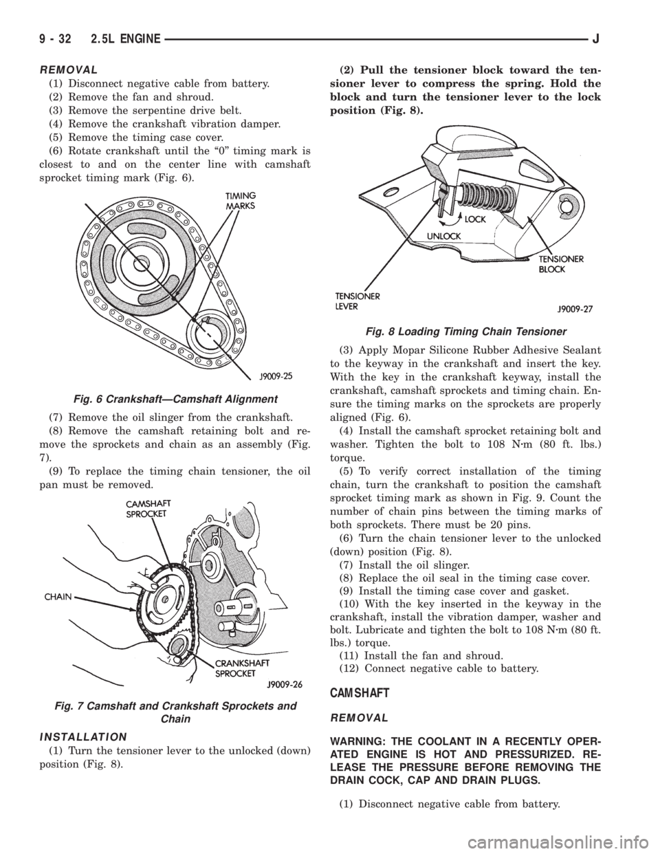
(6) Rotate crankshaft until the ``0'' timing mark is
closest to and on the center line with camshaft
sprocket timing mark (Fig. 6).
(7) Remove the oil slinger from the crankshaft.
(8) Remove the camshaft retaining bolt and re-
move the sprockets and chain as an assembly (Fig.
7).
(9) To replace the timing chain tensioner, the oil
pan must be removed.
INSTALLATION
(1) Turn the tensioner lever to the unlocked (down)
position (Fig. 8).(2) Pull the tensioner block toward the ten-
sioner lever to compress the spring. Hold the
block and turn the tensioner lever to the lock
position (Fig. 8).
(3) Apply Mopar Silicone Rubber Adhesive Sealant
to the keyway in the crankshaft and insert the key.
With the key in the crankshaft keyway, install the
crankshaft, camshaft sprockets and timing chain. En-
sure the timing marks on the sprockets are properly
aligned (Fig. 6).
(4) Install the camshaft sprocket retaining bolt and
washer. Tighten the bolt to 108 Nzm (80 ft. lbs.)
torque.
(5) To verify correct installation of the timing
chain, turn the crankshaft to position the camshaft
sprocket timing mark as shown in Fig. 9. Count the
number of chain pins between the timing marks of
both sprockets. There must be 20 pins.
(6) Turn the chain tensioner lever to the unlocked
(down) position (Fig. 8).
(7) Install the oil slinger.
(8) Replace the oil seal in the timing case cover.
(9) Install the timing case cover and gasket.
(10) With the key inserted in the keyway in the
crankshaft, install the vibration damper, washer and
bolt. Lubricate and tighten the bolt to 108 Nzm (80 ft.
lbs.) torque.
(11) Install the fan and shroud.
(12) Connect negative cable to battery.
CAMSHAFT
REMOVAL
WARNING: THE COOLANT IN A RECENTLY OPER-
ATED ENGINE IS HOT AND PRESSURIZED. RE-
LEASE THE PRESSURE BEFORE REMOVING THE
DRAIN COCK, CAP AND DRAIN PLUGS.
(1) Disconnect negative cable from battery.
Fig. 6 CrankshaftÐCamshaft Alignment
Fig. 7 Camshaft and Crankshaft Sprockets and
Chain
Fig. 8 Loading Timing Chain Tensioner
9 - 32 2.5L ENGINEJ
Page 1313 of 2158
tor in the Component Removal/Installation section of
Group 8D, Ignition Systems.
(14) Install the distributor and ignition wires. Re-
fer to Distributor in the Component Removal/Instal-
lation section of Group 8D, Ignition Systems.
(15) Install the radiator or radiator and condenser,
if equipped with A/C.
(16) Fill the cooling system.
(17) Connect negative cable to battery.
CAMSHAFT PIN REPLACEMENT
REMOVAL
WARNING: DO NOT LOOSEN THE RADIATOR
DRAIN COCK WITH THE SYSTEM HOT AND PRES-
SURIZED BECAUSE SERIOUS BURNS FROM COOL-
ANT CAN OCCUR.
(1) Disconnect negative cable from battery.
(2) Drain the radiator. DO NOT waste reusable
coolant. Drain the coolant into a clean container.
(3) Remove the fan and shroud.
(4) Disconnect the radiator overflow tube, radiator
hoses, automatic transmission fluid cooler pipes (if
equipped).
(5) Remove the radiator.
(6) If equipped with air conditioning:
CAUTION: DO NOT loosen or disconnect any air
conditioner system fittings. Move the condenser
and receiver/drier aside as a complete assembly.
(a) Remove the A/C compressor serpentine drive
belt idler pulley.
(b) Disconnect and remove the generator.
(c) Remove the A/C condenser attaching bolts
and move the condenser and receiver/drier assem-
bly up and out of the way.
(7) Remove the serpentine drive belt.
(8) Remove the crankshaft vibration damper.
(9) Remove the timing case cover. Clean the gasket
material from the cover.
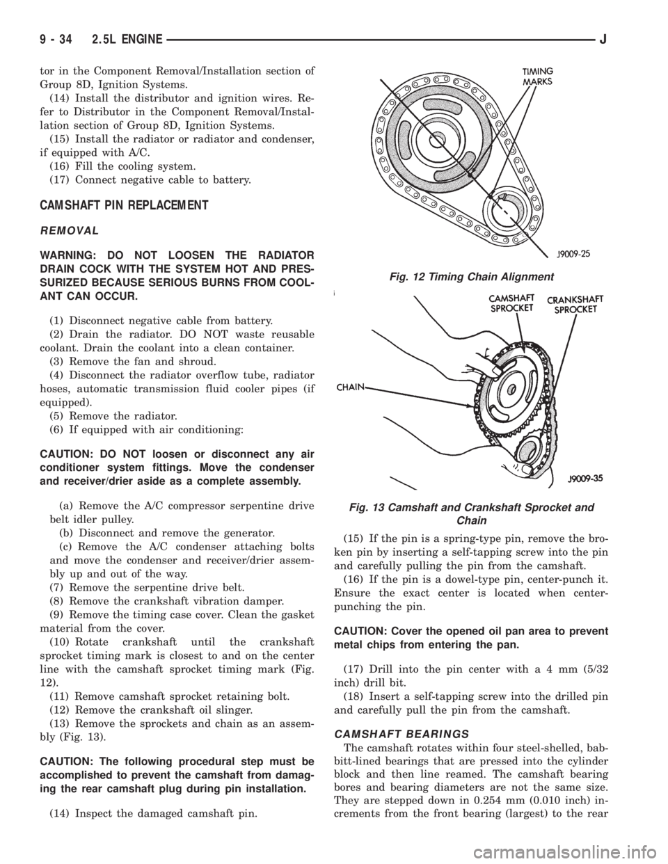
(10) Rotate crankshaft until the crankshaft
sprocket timing mark is closest to and on the center
line with the camshaft sprocket timing mark (Fig.
12).
(11) Remove camshaft sprocket retaining bolt.
(12) Remove the crankshaft oil slinger.
(13) Remove the sprockets and chain as an assem-
bly (Fig. 13).
CAUTION: The following procedural step must be
accomplished to prevent the camshaft from damag-
ing the rear camshaft plug during pin installation.
(14) Inspect the damaged camshaft pin.(15) If the pin is a spring-type pin, remove the bro-
ken pin by inserting a self-tapping screw into the pin
and carefully pulling the pin from the camshaft.
(16) If the pin is a dowel-type pin, center-punch it.
Ensure the exact center is located when center-
punching the pin.
CAUTION: Cover the opened oil pan area to prevent
metal chips from entering the pan.
(17) Drill into the pin center witha4mm(5/32
inch) drill bit.
(18) Insert a self-tapping screw into the drilled pin
and carefully pull the pin from the camshaft.
CAMSHAFT BEARINGS
The camshaft rotates within four steel-shelled, bab-
bitt-lined bearings that are pressed into the cylinder
block and then line reamed. The camshaft bearing
bores and bearing diameters are not the same size.
They are stepped down in 0.254 mm (0.010 inch) in-
crements from the front bearing (largest) to the rear
Fig. 12 Timing Chain Alignment
Fig. 13 Camshaft and Crankshaft Sprocket and
Chain
9 - 34 2.5L ENGINEJ
Page 1314 of 2158
bearing (smallest). This permits easier removal and
installation of the camshaft. The camshaft bearings
are pressure lubricated.
It is not advisable to attempt to replace cam-
shaft bearings unless special removal and in-
stallation tools are available.
Camshaft end play is maintained by the load
placed on the camshaft by the oil pump and distrib-
utor drive gear. The helical cut of the gear holds the
camshaft sprocket thrust face against the cylinder
block face.
INSTALLATION
(1) Clean the camshaft pin hole.
(2) Compress the center of the replacement spring
pin with vise grips.
(3) Carefully drive the pin into the camshaft pin
hole until it is seated.
(4) Install the camshaft sprocket, crankshaft
sprocket and timing chain with the timing marks
aligned (Fig. 12).
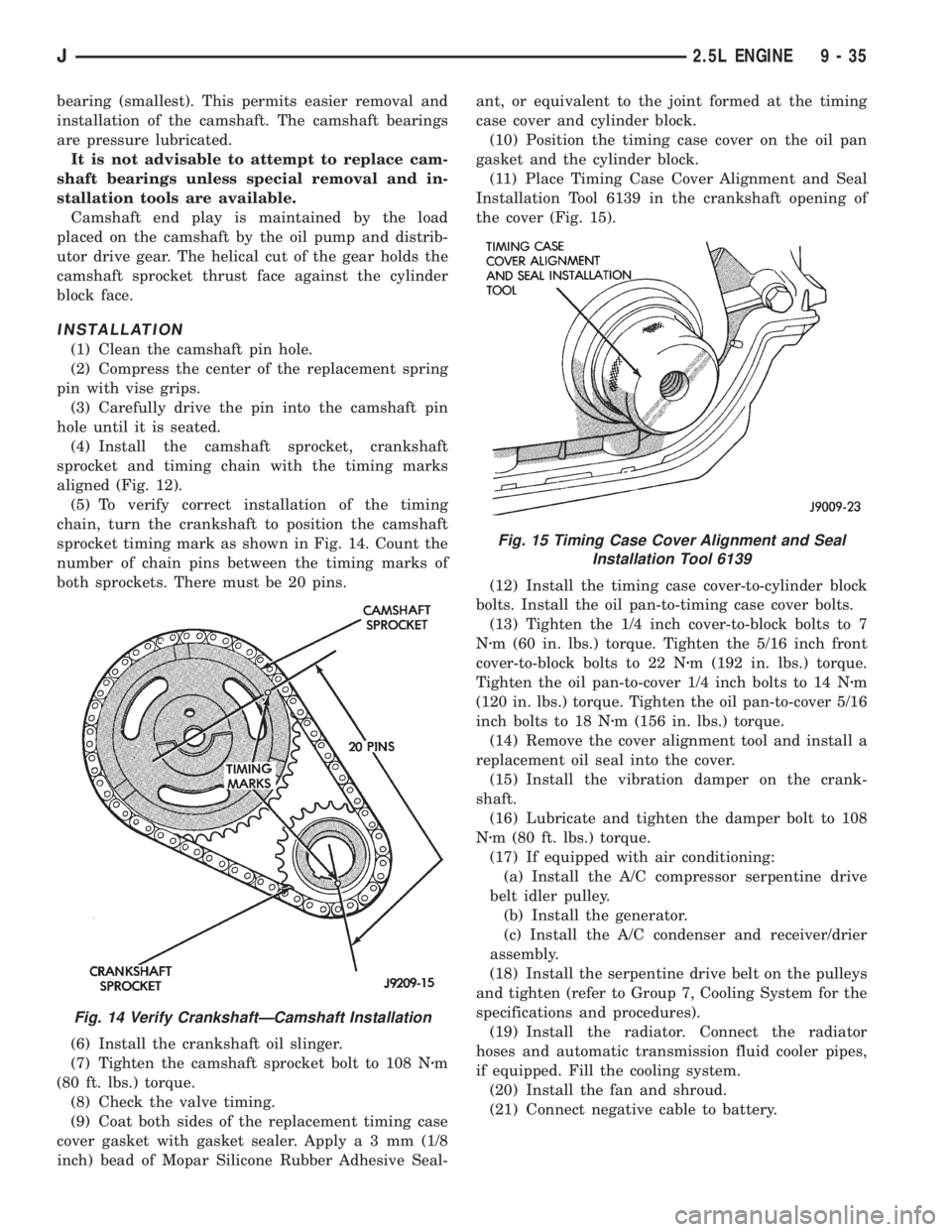
(5) To verify correct installation of the timing
chain, turn the crankshaft to position the camshaft
sprocket timing mark as shown in Fig. 14. Count the
number of chain pins between the timing marks of
both sprockets. There must be 20 pins.
(6) Install the crankshaft oil slinger.
(7) Tighten the camshaft sprocket bolt to 108 Nzm
(80 ft. lbs.) torque.
(8) Check the valve timing.
(9) Coat both sides of the replacement timing case
cover gasket with gasket sealer. Applya3mm(1/8
inch) bead of Mopar Silicone Rubber Adhesive Seal-ant, or equivalent to the joint formed at the timing
case cover and cylinder block.
(10) Position the timing case cover on the oil pan
gasket and the cylinder block.
(11) Place Timing Case Cover Alignment and Seal
Installation Tool 6139 in the crankshaft opening of
the cover (Fig. 15).
(12) Install the timing case cover-to-cylinder block
bolts. Install the oil pan-to-timing case cover bolts.
(13) Tighten the 1/4 inch cover-to-block bolts to 7
Nzm (60 in. lbs.) torque. Tighten the 5/16 inch front
cover-to-block bolts to 22 Nzm (192 in. lbs.) torque.
Tighten the oil pan-to-cover 1/4 inch bolts to 14 Nzm
(120 in. lbs.) torque. Tighten the oil pan-to-cover 5/16
inch bolts to 18 Nzm (156 in. lbs.) torque.
(14) Remove the cover alignment tool and install a
replacement oil seal into the cover.
(15) Install the vibration damper on the crank-
shaft.
(16) Lubricate and tighten the damper bolt to 108
Nzm (80 ft. lbs.) torque.
(17) If equipped with air conditioning:
(a) Install the A/C compressor serpentine drive
belt idler pulley.
(b) Install the generator.
(c) Install the A/C condenser and receiver/drier
assembly.
(18) Install the serpentine drive belt on the pulleys
and tighten (refer to Group 7, Cooling System for the
specifications and procedures).
(19) Install the radiator. Connect the radiator
hoses and automatic transmission fluid cooler pipes,
if equipped. Fill the cooling system.
(20) Install the fan and shroud.
(21) Connect negative cable to battery.
Fig. 14 Verify CrankshaftÐCamshaft Installation
Fig. 15 Timing Case Cover Alignment and Seal
Installation Tool 6139
J2.5L ENGINE 9 - 35