1995 JEEP YJ torque
[x] Cancel search: torquePage 181 of 2158

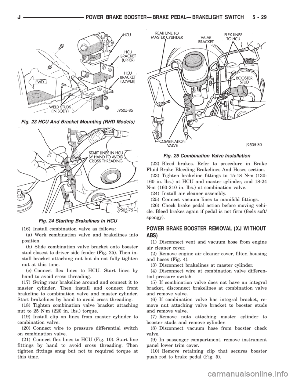
(16) Install combination valve as follows:
(a) Work combination valve and brakelines into
position.
(b) Slide combination valve bracket onto booster
stud closest to driver side fender (Fig. 25). Then in-
stall bracket attaching nut but do not fully tighten
nut at this time.
(c) Connect flex lines to HCU. Start lines by
hand to avoid cross threading.
(17) Swing rear brakeline around and connect it to
master cylinder. Then install and connect front
brakeline to combination valve and master cylinder.
Start brakelines by hand to avoid cross threading.
(18) Tighten combination valve bracket attaching
nut to 25 Nzm (220 in. lbs.) torque.
(19) Install clip on lines from master cylinder to
combination valve.
(20) Connect wire to pressure differential switch
on combination valve.
(21) Connect flex lines to HCU (Fig. 10). Start line
fittings by hand to avoid cross threading. Then
tighten fittings snug but not to required torque at
this time.(22) Bleed brakes. Refer to procedure in Brake
Fluid-Brake Bleeding-Brakelines And Hoses section.
(23) Tighten brakeline fittings to 15-18 Nzm (130-
160 in. lbs.) at HCU and master cylinder, and 18-24
Nzm (160-210 in. lbs.) at combination valve.
(24) Install air cleaner assembly.
(25) Connect vacuum lines to manifold fittings.
(26) Check brake pedal action before moving vehi-
cle. Bleed brakes again if pedal is not firm (feels soft/
spongy).POWER BRAKE BOOSTER REMOVAL (XJ WITHOUT
ABS)
(1) Disconnect vent and vacuum hose from engine
air cleaner cover.
(2) Remove engine air cleaner cover, filter, housing
and hoses (Fig. 4).
(3) Disconnect brakelines at master cylinder.
(4) Disconnect wire at combination valve differen-
tial pressure switch.
(5) If combination valve does not have an integral
bracket, disconnect brakelines at combination valve
and remove valve.
(6) If combination valve has integral bracket, re-
move nut attaching valve bracket to booster studs
and remove valve.
(7) Remove nuts attaching master cylinder to
booster studs and remove cylinder.
(8) Disconnect vacuum hose from booster check
valve.
(9) In passenger compartment, remove instrument
panel lower trim cover.
(10) Remove retaining clip that secures booster
push rod to brake pedal (Fig. 5).
Fig. 23 HCU And Bracket Mounting (RHD Models)
Fig. 24 Starting Brakelines In HCU
Fig. 25 Combination Valve Installation
JPOWER BRAKE BOOSTERÐBRAKE PEDALÐBRAKELIGHT SWITCH 5 - 29
Page 182 of 2158

(11) Remove nuts attaching booster to passenger
compartment side of dash panel.
(12) In engine compartment, slide booster studs
out of dash panel, tilt booster upward, and remove
booster from engine compartment.
(13) Remove dash seal from booster.
(14) If booster is only being removed for access to
other components, cover booster front opening with
clean shop towel.
POWER BRAKE BOOSTER INSTALLATION (XJ
WITHOUT ABS)
(1) If original booster is being installed, test check
valve with vacuum tool before booster installation.
Replace check valve if it will not hold vacuum.
(2) Install dash seal on booster.
(3) Align and position booster on dash panel (Fig.
17).
(4) In passenger compartment, install nuts that at-
tach booster to dash panel. Tighten nuts just enough
to hold booster in place.
(5) Slide booster push rod onto brake pedal. Then
secure push rod to pedal pin with retaining clip.
(6) Tighten booster attaching nuts to 41 Nzm (30 ft.
lbs.) on XJ and 34 Nzm (25 ft. lbs.) on YJ.
(7) Install instrument panel lower trim cover.
(8) If original master cylinder is being installed,
check condition of seal at rear of master cylinder
(Fig. 18). Clean and reposition seal if dislodged. Re-
place seal if cut, or torn.
(9) Clean cylinder mounting surface of brake
booster. Use shop towel wetted with brake cleaner for
this purpose. Dirt, grease, or similar materials will
prevent proper cylinder seating and could result in
vacuum leak.
(10) Align and install master cylinder on booster
studs. Tighten cylinder attaching nuts to 13-25 Nzm
(115-220 in. lbs.) torque.
(11) Connect vacuum hose to booster check valve.
(12) Connect and secure brakelines to combination
valve and master cylinder. Start all brakeline fittings
by hand to avoid cross threading.
(13) If combination valve has integral bracket, po-
sition bracket on booster studs. Then install and
tighten bracket attaching nuts to 13-25 Nzm (115-220
in. lbs.) torque.
(14) Connect wire to combination valve switch.
(15) Top off master cylinder fluid level.
(16) Bleed brakes. Refer to procedures in section
on brake bleeding.
(17) Install engine air cleaner and hoses.
(18) Verify proper brake operation before moving
vehicle.
POWER BRAKE BOOSTER REMOVAL (YJ)
(1) Disconnect brakelines at master cylinder. Then
loosen lines at combination valve and move lines
away from cylinder.
(2) Remove nuts master cylinder to booster studs.
(3) If combination valve has integral bracket, slide
bracket off studs and move valve aside.
(4) Remove master cylinder. Slide cylinder off
studs and remove it from engine compartment.
(5) Working under instrument panel, remove re-
tainer clip that secures booster push rod to brake
pedal.
(6) Disconnect vacuum hose at booster check valve.
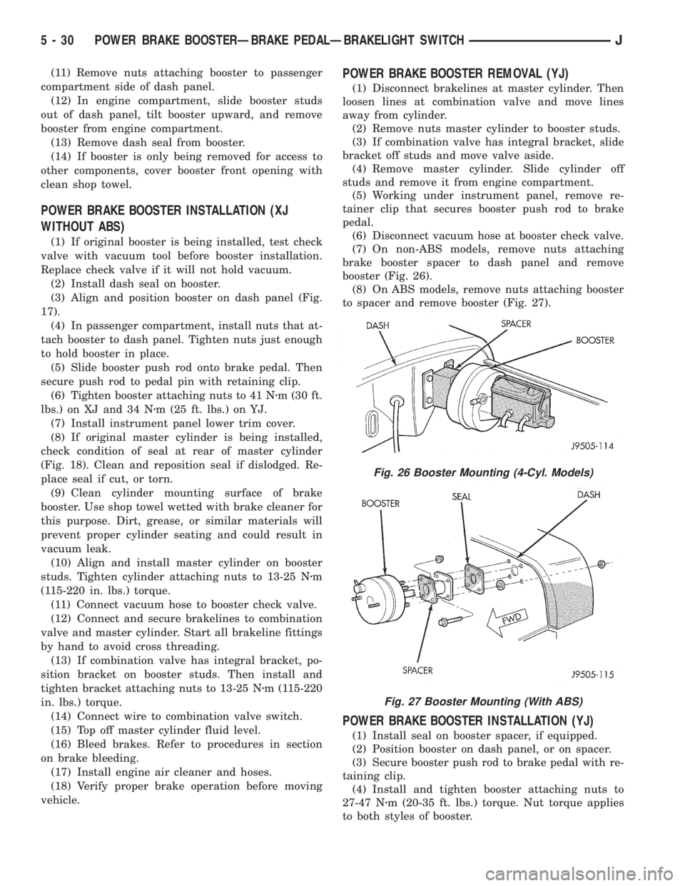
(7) On non-ABS models, remove nuts attaching
brake booster spacer to dash panel and remove
booster (Fig. 26).
(8) On ABS models, remove nuts attaching booster
to spacer and remove booster (Fig. 27).
POWER BRAKE BOOSTER INSTALLATION (YJ)
(1) Install seal on booster spacer, if equipped.
(2) Position booster on dash panel, or on spacer.
(3) Secure booster push rod to brake pedal with re-
taining clip.
(4) Install and tighten booster attaching nuts to
27-47 Nzm (20-35 ft. lbs.) torque. Nut torque applies
to both styles of booster.
Fig. 26 Booster Mounting (4-Cyl. Models)
Fig. 27 Booster Mounting (With ABS)
5 - 30 POWER BRAKE BOOSTERÐBRAKE PEDALÐBRAKELIGHT SWITCHJ
Page 190 of 2158

air gap should be 0.40 to 1.3 mm (0.0157 to 0.051
in.). If gap is incorrect, the sensor is either loose, or
damaged.
A rear sensor air gap adjustment is only needed
when reinstalling an original sensor. Replacement
sensors have an air gap spacer attached to the sensor
pickup face. The spacer establishes correct air gap
when pressed against the tone ring during installa-
tion. As the tone ring rotates, it peels the spacer off
the sensor to create the required air gap. Rear sensor
air gap is 0.92-1.45 mm (0.036-0.057 in.).
Sensor air gap measurement, or adjustment proce-
dures are provided in this section. Refer to the front,
or rear sensor removal and installation procedures as
required.
FRONT WHEEL SENSOR REMOVAL
(1) Raise vehicle and turn wheel outward for easier
access to sensor.
(2) Remove sensor wire from mounting brackets.
(3) Clean sensor and surrounding area with shop
towel before removal.
(4) Remove bolt attaching sensor to steering
knuckle and remove sensor.
(5) remove sensor wire from brackets on body and
steering knuckle.
(6) Unseat sensor wire grommet in wheel house
panel.
(7) In engine compartment, disconnect sensor wire
connector at harness plug. Then remove sensor and
wire.
FRONT WHEEL SENSOR INSTALLATION
(1) Iforiginalsensor will be installed, wipe all
traces of old spacer material off sensor pickup face.
Use a dry shop towel for this purpose.
(2) Apply Mopar Lock N' Seal or Loctite 242 to bolt
that secures sensor in steering knuckle. Use new
sensor bolt if original bolt is worn or damaged.
(3) Position sensor on steering knuckle. Seat sen-
sor locating tab in hole in knuckle and install sensor
attaching bolt finger tight.
(4) Tighten sensor attaching bolt to 14 Nzm (11 ft.
lbs.) torque.
(5) If original sensor has been installed, check sen-
sor air gap. Air gap should be 0.40 to 1.3 mm (0.0157
to 0.051 in.). If gap is incorrect, sensor is either loose,
or damaged.
(6) Secure sensor wire to steering knuckle and
body brackets.
(7) Route sensor wire forward and behind shock
absorber. Then attach sensor wire to spring seat
bracket with grommets on sensor wire.
(8) Route sensor wire to outer sill bracket. Remove
all twists or kinks from wire.
(9) Attach sensor wire to sill bracket with grom-
met. Be sure wire is free of twists and kinks.(10) Verify sensor wire routing. Wire should loop
forward and above sill bracket. Loose end of wire
should be below sill bracket and towards brake hose.
(11) Seat sensor wire grommet in body panel and
clip wire to brake line at grommet location.
(12) Connect sensor wire to harness in engine com-
partment.
REAR WHEEL SENSOR REMOVAL
(1) On XJ models, raise and fold rear seat forward
for access to rear sensor connectors (Fig. 9).
(2) Disconnect sensors at rear harness connectors.
(3) Push sensor grommets and sensor wires
through floorpan.
(4) Raise vehicle.
(5) Disconnect sensor wires at rear axle connectors.
(6) Remove wheel and tire assembly.
(7) Remove brake drum.
(8) Remove clips securing sensor wires to brake-
lines, rear axle and, brake hose.
(9) Unseat sensor wire support plate grommet.
(10) Remove bolt attaching sensor to bracket and
remove sensor.
REAR WHEEL SENSOR INSTALLATION AND
ADJUSTMENT
(1) Iforiginal sensoris being installed, remove
any remaining pieces of cardboard spacer from sen-
sor pickup face. Use dry shop towel only to remove
old spacer material.
(2) Insert sensor wire through support plate hole.
Then seat sensor grommet in support plate.
(3) Apply Mopar Lock N' Seal or Loctite 242 to
Fig. 9 Acceleration Switch And Rear Sensor
Connections (XJ)
5 - 38 ABS OPERATION AND SERVICEJ
Page 191 of 2158

original sensor bolt. Use new bolt if original is worn
or damaged.
(4) Install sensor bolt finger tight only at this time.
(5) Iforiginalrear sensor was installed, adjust
sensor air gap to 0.92-1.45 mm (0.036-0.057 in.). Use
feeler gauge to measure air gap (Fig. 10). Tighten
sensor bolt to 11 Nzm (11 ft. lbs.) torque.
(6) Ifnewsensor was installed, push cardboard
spacer on sensor face against tone ring (Fig. 11).
Then tighten sensor bolt to 8 Nzm (6 ft. lbs.) torque.
Correct air gap will be established as tone ring ro-
tates and peels spacer off sensor face.
(7) On YJ, connect rear sensor wires to connectors
at axle. On XJ, route sensor wires to rear seat area.
(8) Feed sensor wires through floorpan access hole
and seat sensor grommets in floorpan.
(9) Verify that rear sensor wires are secured to
rear brake hose and axle with clips. Verify that wire
is clear of rotating components.
(10) Install brake drum and wheel.
(11) Lower vehicle.
(12) On XJ, connect sensor wire to harness connec-
tor. Then reposition carpet and fold rear seat down.
ACCELERATION SWITCH REMOVAL
(1) On XJ models, tilt rear seat assembly forward
for access to sensor (Fig. 12).(2) On YJ models, move driver seat forward or
rearward for access to sensor and mounting bracket
(Fig. 12).
(3) Disconnect switch harness.
(4) On XJ models, remove screws attaching switch
to bracket. Then remove switch.
(5) On YJ models, remove screws attaching switch
bracket to floorpan. Then remove switch from
bracket.
ACCELERATION SWITCH INSTALLATION
(1) Note position of locating arrow on switch.
Switch must be positioned so arrow faces forward.
Fig. 10 Setting Air Gap On Original Rear Sensor
Fig. 11 Location Of Spacer On New Rear Sensor
Fig. 12 Acceleration Switch Mounting (XJ/YJ)
JABS OPERATION AND SERVICE 5 - 39
Page 192 of 2158

CAUTION: The mercury switch (inside the accelera-
tion switch), will not function properly if the switch
is mispositioned. Verify that the switch locating ar-
row is pointing to the front of the vehicle.
(2) Position switch in mounting bracket.
(3) Install and tighten switch attaching screws to
2-4 Nzm (17-32 in. lbs.) torque.
(4) Connect harness to switch. Be sure harness
connecter is firmly seated.
(5) Move seat back to normal position.
ECU REMOVAL (XJ MODELS)
On left hand drive models, the ECU is located to
the right of the steering column near the heater duct
(Fig. 13). On right hand drive models, the ECU is lo-
cated near the right side cowl panel adjacent to the
dash (Fig. 14).
(1) Turn ignition key to Off position.
(2) Remove lower finish panel from instrument
panel for added working clearance if necessary.
(3) Remove ECU mounting bracket attaching bolts/
nuts.
(4) Release strap that secures ECU harness con-
nector to pin terminals (Fig. 15). Use tool such as
small flat blade screwdriver to lift and release strap.(5) Disconnect harness connector from ECU. Tilt
connector upward to disengage it from ECU pin ter-
minals. Then slide it out of retaining tangs in ECU.
(6) Remove ECU and mounting bracket as assem-
bly.
ECU INSTALLATION (XJ MODELS)
(1) If ECU is being replaced, install it on mounting
bracket and tighten fasteners to 10-14 Nzm (85-125
in. lbs.) torque
Fig. 13 Antilock ECU Mounting (Left Hand Drive XJ)
Fig. 14 Antilock ECU Mounting (Right Hand Drive XJ)
Fig. 15 ECU Harness Connector Attachment (XJ)
5 - 40 ABS OPERATION AND SERVICEJ
Page 193 of 2158

(2) Align and attach harness connector to ECU.
Slide connector into engagement with tangs on ECU.
Then tilt connector downward and into engagement
with ECU pin terminals. Exercise care as pin termi-
nals can be damaged if connector is forced into place.
(3) Connect harness to security alarm module, if
equipped.
(4) Position ECU bracket under instrument panel.
(5) Install and tighten ECU mounting bracket
bolts/nuts to 8-14 Nzm (75- 125 in. lbs.) torque.
(6) Install trim panel on instrument panel, if re-
moved.
ECU REMOVAL/INSTALLATION (YJ MODELS)
The antilock ECU is attached to the dash panel in-
side the passenger compartment. It is positioned just
above the heater/air conditioning plenum housing, in
line with the glove box (Fig. 16).
The ECU is attached to the dash panel by bolts
and nuts that are accessible from the engine com-
partment. The fasteners are located just to the right
of the battery.
On models with air conditioning, it will be neces-
sary to remove the air conditioning fascia panel and
ducts for access to the ECU and harness connecter.
HCU REMOVAL (XJ)
A new design HCU is used in 1995 models. The
new HCU has built-in accumulators that store the
extra fluid released for antilock mode operation. As a
result, the master cylinder and HCU are no longer
interconnected by hoses.The 1995 and prior hy-
draulic control units are NOT interchangeable.
(1) Disconnect vent hoses at air cleaner cover.
(2) Loosen clamp securing air cleaner hose to in-
take manifold. Use screwdriver to tap clamp loose.
(3) Remove air cleaner cover and hose. Then re-
move air filter from air cleaner shell (Fig. 17).
(4) Remove two bolts and one nut that secure air
cleaner housing to body panel (Fig. 17).
(5) Remove air cleaner housing from engine com-
partment.
Fig. 16 ECU Location (YJ)
Fig. 17 Air Cleaner Components
JABS OPERATION AND SERVICE 5 - 41
Page 195 of 2158

HCU INSTALLATION (XJ)
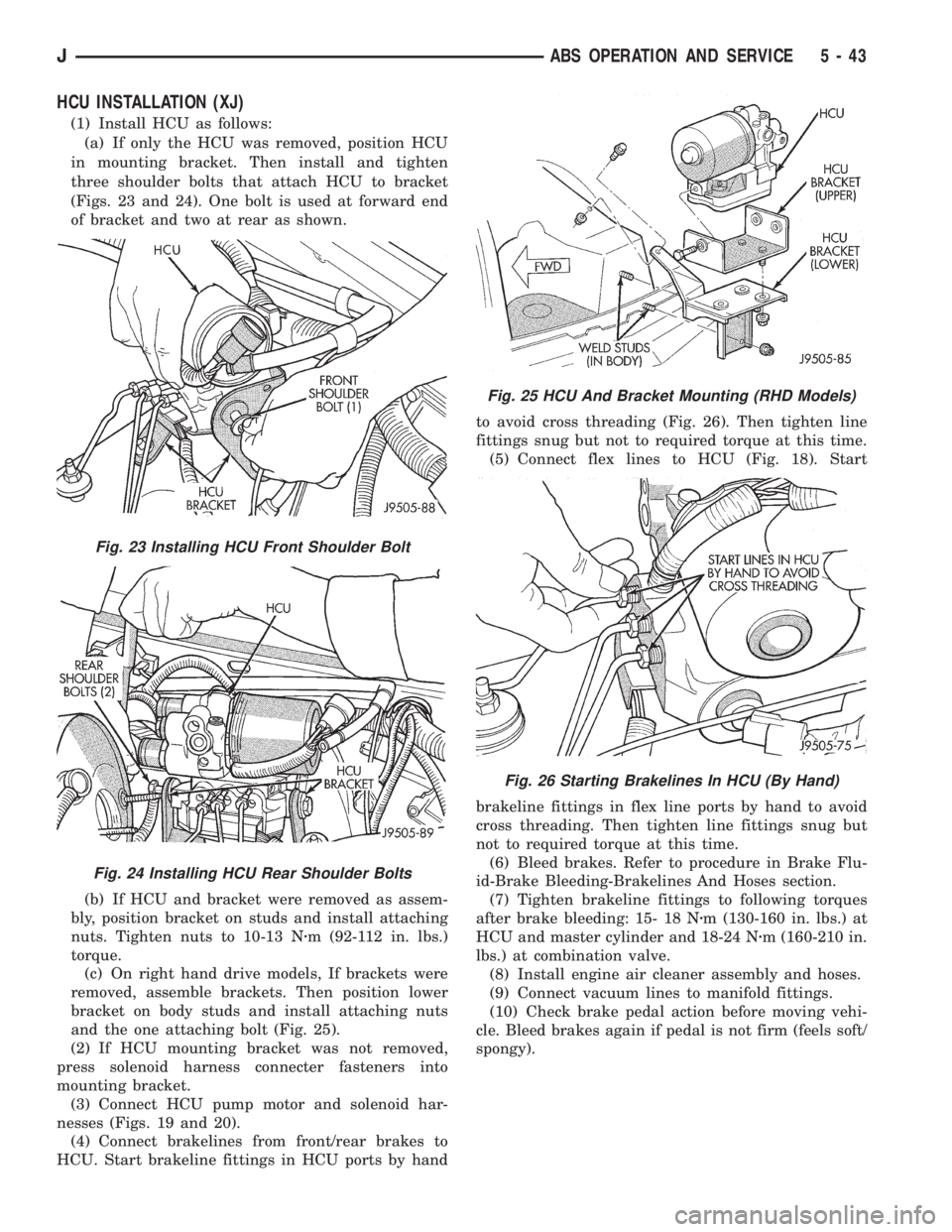
(1) Install HCU as follows:
(a) If only the HCU was removed, position HCU
in mounting bracket. Then install and tighten
three shoulder bolts that attach HCU to bracket
(Figs. 23 and 24). One bolt is used at forward end
of bracket and two at rear as shown.
(b) If HCU and bracket were removed as assem-
bly, position bracket on studs and install attaching
nuts. Tighten nuts to 10-13 Nzm (92-112 in. lbs.)
torque.
(c) On right hand drive models, If brackets were
removed, assemble brackets. Then position lower
bracket on body studs and install attaching nuts
and the one attaching bolt (Fig. 25).
(2) If HCU mounting bracket was not removed,
press solenoid harness connecter fasteners into
mounting bracket.
(3) Connect HCU pump motor and solenoid har-
nesses (Figs. 19 and 20).
(4) Connect brakelines from front/rear brakes to
HCU. Start brakeline fittings in HCU ports by handto avoid cross threading (Fig. 26). Then tighten line
fittings snug but not to required torque at this time.
(5) Connect flex lines to HCU (Fig. 18). Start
brakeline fittings in flex line ports by hand to avoid
cross threading. Then tighten line fittings snug but
not to required torque at this time.
(6) Bleed brakes. Refer to procedure in Brake Flu-
id-Brake Bleeding-Brakelines And Hoses section.
(7) Tighten brakeline fittings to following torques
after brake bleeding: 15- 18 Nzm (130-160 in. lbs.) at
HCU and master cylinder and 18-24 Nzm (160-210 in.
lbs.) at combination valve.
(8) Install engine air cleaner assembly and hoses.
(9) Connect vacuum lines to manifold fittings.
(10) Check brake pedal action before moving vehi-
cle. Bleed brakes again if pedal is not firm (feels soft/
spongy).
Fig. 23 Installing HCU Front Shoulder Bolt
Fig. 24 Installing HCU Rear Shoulder Bolts
Fig. 25 HCU And Bracket Mounting (RHD Models)
Fig. 26 Starting Brakelines In HCU (By Hand)
JABS OPERATION AND SERVICE 5 - 43
Page 196 of 2158

HCU REMOVAL (YJ)
(1) Place shop towels under master cylinder and
HCU brakelines.
(2) Disconnect flex lines at upper part of HCU.
(3) Disconnect solenoid and pump harness wires at
HCU harness connecters.
(4) Disconnect lines to front/rear brakes at lower
part of HCU.
(5) Remove shoulder bolts attaching HCU to
mounting bracket and remove HCU.
HCU INSTALLATION (YJ)
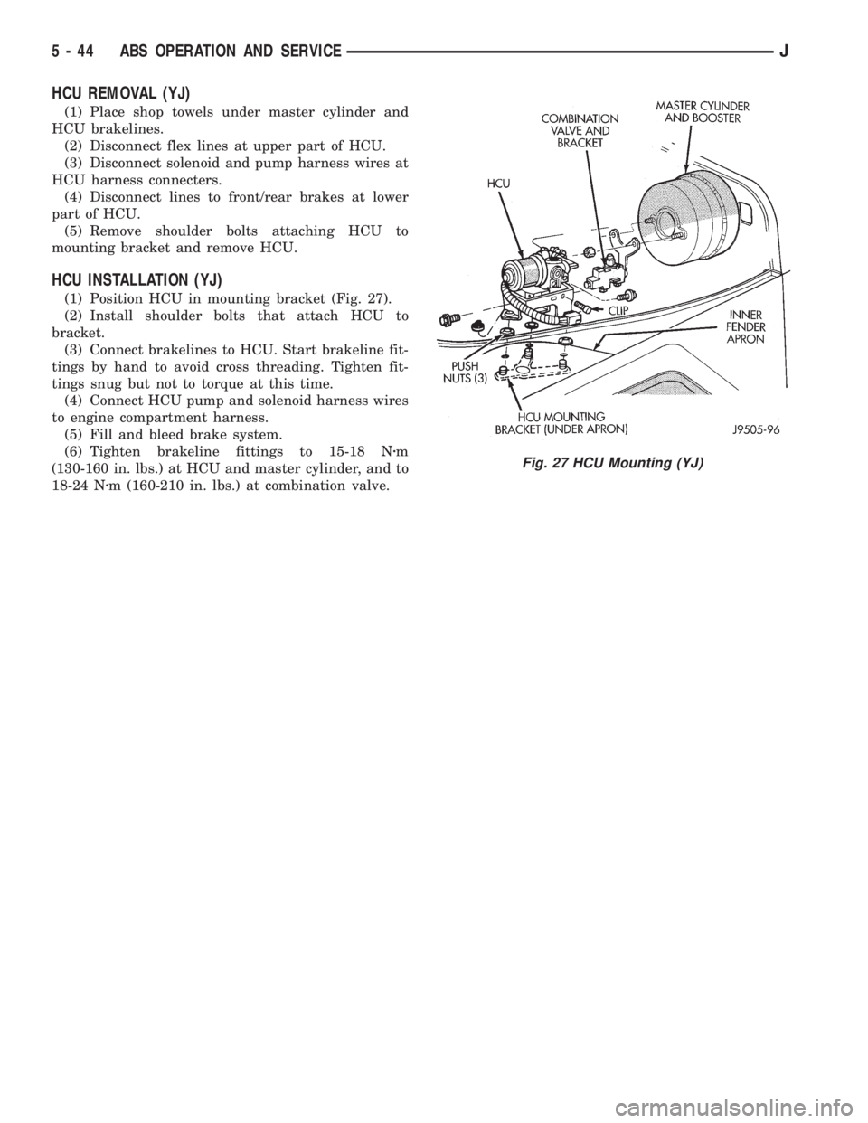
(1) Position HCU in mounting bracket (Fig. 27).
(2) Install shoulder bolts that attach HCU to
bracket.
(3) Connect brakelines to HCU. Start brakeline fit-
tings by hand to avoid cross threading. Tighten fit-
tings snug but not to torque at this time.
(4) Connect HCU pump and solenoid harness wires
to engine compartment harness.
(5) Fill and bleed brake system.
(6) Tighten brakeline fittings to 15-18 Nzm
(130-160 in. lbs.) at HCU and master cylinder, and to
18-24 Nzm (160-210 in. lbs.) at combination valve.
Fig. 27 HCU Mounting (YJ)
5 - 44 ABS OPERATION AND SERVICEJ