1995 JEEP YJ torque
[x] Cancel search: torquePage 147 of 2158
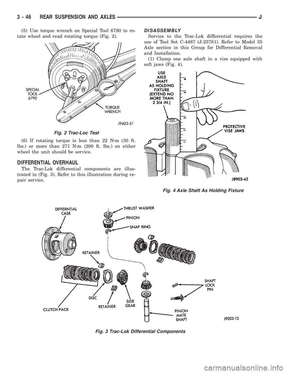
(5) Use torque wrench on Special Tool 6790 to ro-
tate wheel and read rotating torque (Fig. 2).
(6) If rotating torque is less than 22 Nzm (30 ft.
lbs.) or more than 271 Nzm (200 ft. lbs.) on either
wheel the unit should be service.
DIFFERENTIAL OVERHAUL
The Trac-Lok differential components are illus-
trated in (Fig. 3). Refer to this illustration during re-
pair service.
DISASSEMBLY
Service to the Trac-Lok differential requires the
use of Tool Set C-4487 (J-23781). Refer to Model 35
Axle section in this Group for Differential Removal
and Installation.
(1) Clamp one axle shaft in a vise equipped with
soft jaws (Fig. 4).
Fig. 3 Trac-Lok Differential Components
Fig. 2 Trac-Loc Test
Fig. 4 Axle Shaft As Holding Fixture
3 - 46 REAR SUSPENSION AND AXLESJ
Page 151 of 2158
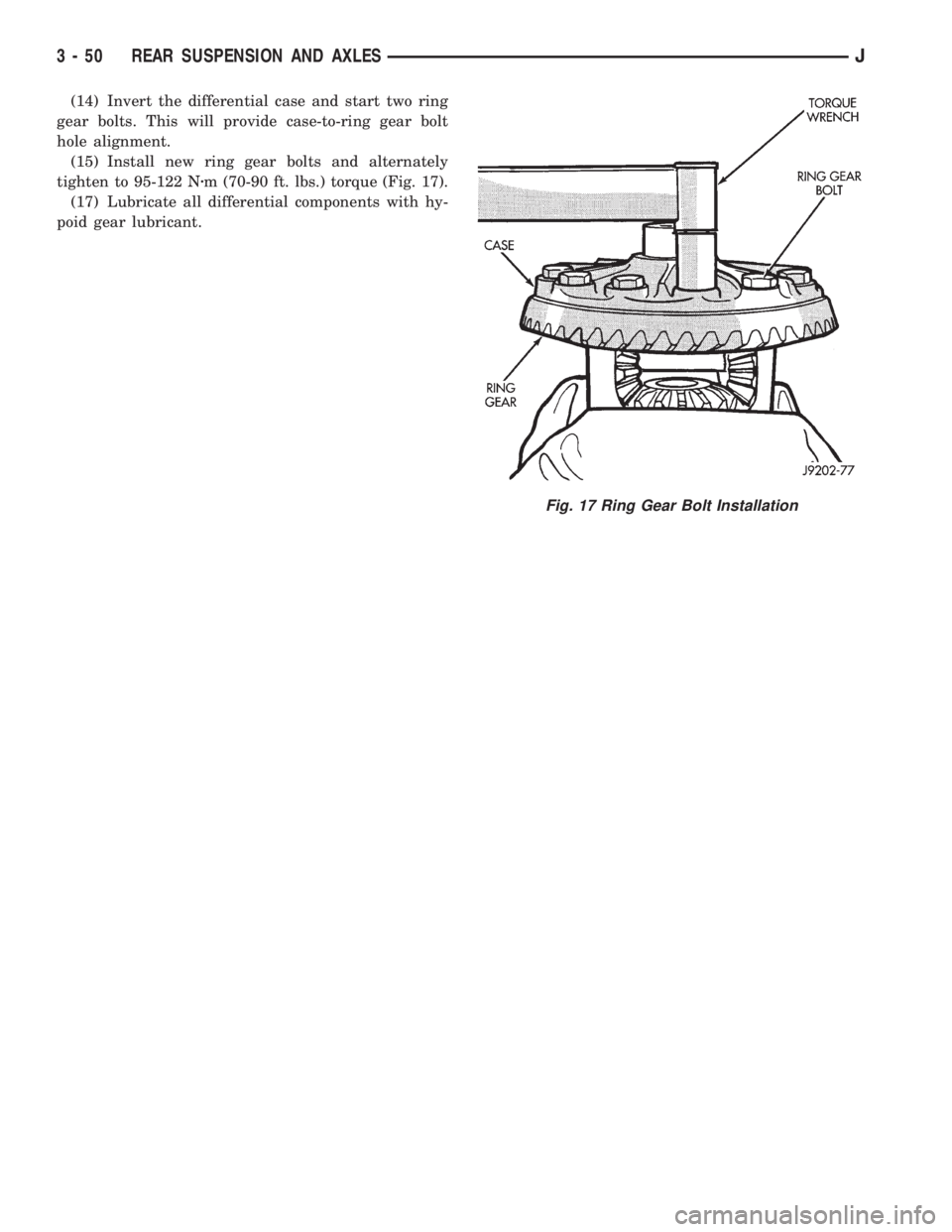
(14) Invert the differential case and start two ring
gear bolts. This will provide case-to-ring gear bolt
hole alignment.
(15) Install new ring gear bolts and alternately
tighten to 95-122 Nzm (70-90 ft. lbs.) torque (Fig. 17).
(17) Lubricate all differential components with hy-
poid gear lubricant.
Fig. 17 Ring Gear Bolt Installation
3 - 50 REAR SUSPENSION AND AXLESJ
Page 152 of 2158

AXLE SPECIFICATIONS
MODEL 35 AXLE
Axle Type...............................Semi-Floating Hypoid
Lubricant................SAE Thermally Stable 80W-90
Lubricant Trailer Tow.............Synthetic 75W-140
Lube Capacity..............................1.66 L (3.50 pts.)
Axle Ratio................................3.07, 3.55, 3.73, 4.10
Differential
Bearing Preload ............................0.1 mm (0.004 in.)
Side Gear Clearance ............0-0.15 mm (0-0.006 in.)
Ring Gear
Diameter .......................................19.2 cm (7.562 in.)
Backlash.........................0-0.15 mm (0.005-0.008 in.)
Pinion Std. Depth...................96.8 mm (3.813 in.)
Pinion Bearing Preload
Original Bearing ....................1-2Nzm (10-20 in. lbs.)
New Bearing .......................1.5-4Nzm (15-35 in. lbs.)
8 1/4 AXLE
Axle Type................................Semi-floating, hypoid
Lubricant...............................................SAE 75W-90
Lube Capacity................................2.08 L (4.4 pts.)
Axle Ratios.........................................3.07 3.55 4.10
Differential
Side Gear Clearance ..................0.12 mm (0.005 in.)
Case Flange Runout ..................0.07 mm (0.003 in.)
Bearing Preload ...........................95 Nzm (70 ft. lbs.)
Ring Gear
Diameter .......................................20.95 cm (8.25 in.)
Backlash....................0.12-0.20 mm (0.005-0.008 in.)
Runout .......................................0.127 mm (0.005 in.)
Pinion Bearing
Preload ....................................1-2 Nzm (10-20 in.lbs.)
TORQUE SPECIFICATIONS
XJ REAR SUSPENSION COMPONENTS
DESCRIPTION ................................................TORQUE
Shock Absorber
Upper Bolt ...................................23 Nzm (17 ft. lbs.)
Lower Nut ....................................62 Nzm (46 ft. lbs.)
Stabilizer Bar
Clamp Bolt ...................................54 Nzm (40 ft. lbs.)
Link Upper Bolt ............................12 Nzm (9 ft. lbs.)
Link Lower Nut ..........................74 Nzm (55 ft. lbs.)
Spring
U-Bolt Nut ...................................70 Nzm (52 ft. lbs.)
Front Pivot Bolt ......................148 Nzm (109 ft. lbs.)
Upper Shackle Bolt .................148 Nzm (109 ft. lbs.)
Lower Shackle Bolt ...................108 Nzm (80 ft. lbs.)
YJ REAR SUSPENSION COMPONENTS
DESCRIPTION ................................................TORQUE
Shock Absorber
Upper Nut ....................................61 Nzm (45 ft. lbs.)
Lower Nut ....................................61 Nzm (45 ft. lbs.)
Track Bar
Frame Bracket Nut.................142 Nzm (105 ft. lbs.)
Axle Bracket Nut ....................142 Nzm (105 ft. lbs.)Spring
U-Bolt Nut .................................122 Nzm (90 ft. lbs.)
Rear Shackle Bolts..................136 Nzm (100 ft. lbs.)
Front Pivot Bolt ......................142 Nzm (105 ft. lbs.)
MODEL 35 AXLE
DESCRIPTION ................................................TORQUE
Fill Hole Plug...........................34 Nzm (25 ft. lbs.)
Diff. Cover Bolt........................41 Nzm (30 ft. lbs.)
Bearing Cap Bolt.....................77 Nzm (57 ft. lbs.)
Pinion Nut...............292-427 Nzm (215-315 ft. lbs.)
Ring Gear Bolt.............95-122 Nzm (70-90 ft. lbs.)
RWAL/ABS Sensor Bolt.........24 Nzm (18. ft. lbs.)
8 1/4 AXLE
DESCRIPTION ................................................TORQUE
Diff. Cover Bolt........................47 Nzm (35 ft. lbs.)
Bearing Cap Bolt.....................95 Nzm (70 ft. lbs.)
Pinion Nut.............................285 Nzm (210 ft. lbs.)
Ring Gear Bolt.........................95 Nzm (70 ft. lbs.)
RWAL/ABS Sensor Bolt.........24 Nzm (18. ft. lbs.)
JREAR SUSPENSION AND AXLES 3 - 51
Page 158 of 2158

pedal. The proper course of action is to bleed the sys-
tem, or replace thin drums and suspect quality brake
lines and hoses.
HARD PEDAL OR HIGH PEDAL EFFORT
A hard pedal or high pedal effort may be due to lin-
ing that is water soaked, contaminated, glazed, or
badly worn. The power booster or check valve could
also be faulty. Test the booster and valve as described
in this section.
BRAKE DRAG
Brake drag occurs when the lining is in constant
contact with the rotor or drum. Drag can occur at one
wheel, all wheels, fronts only, or rears only. It is a
product of incomplete brakeshoe release. Drag can be
minor or severe enough to overheat the linings, ro-
tors and drums. A drag condition also worsens as
temperature of the brake parts increases.
Brake drag also has a direct effect on fuel economy.
If undetected, minor brake drag can be misdiagnosed
as an engine or transmission/torque converter prob-
lem.
Minor drag will usually cause slight surface char-
ring of the lining. It can also generate hard spots in
rotors and drums from the overheat/cool down pro-
cess. In most cases, the rotors, drums, wheels and
tires are quite warm to the touch after the vehicle is
stopped.
Severe drag can char the brake lining all the way
through. It can also distort and score rotors and
drums to the point of replacement. The wheels, tires
and brake components will be extremely hot. In se-
vere cases, the lining may generate smoke as it chars
from overheating.
An additional cause of drag involves the use of in-
correct length caliper mounting bolts. Bolts that are
too long can cause a partial apply condition. The cor-
rect caliper bolts have a shank length of 67 mm
(2.637 in.), plus or minus 0.6 mm (0.0236 in.). Refer
to the Disc Brake service section for more detail on
caliper bolt dimensions and identification.
Some common causes of brake drag are:
²loose or damaged wheel bearing
²seized or sticking caliper or wheel cylinder piston
²caliper binding on bolts or slide surfaces
²wrong length caliper mounting bolts (too long)
²loose caliper mounting bracket
²distorted rotor, brake drum, or shoes
²brakeshoes binding on worn/damaged support
plates
²severely rusted/corroded components
²misassembled components.
If brake drag occurs at all wheels, the problem may
be related to a blocked master cylinder compensatorport or faulty power booster (binds-does not release).
The condition will worsen as brake temperature in-
creases.
The brakelight switch can also be a cause of drag.
An improperly mounted or adjusted brakelight
switch can prevent full brake pedal return. The re-
sult will be the same as if the master cylinder com-
pensator ports are blocked. The brakes would be
partially applied causing drag.
BRAKE FADE
Brake fade is a product of overheating caused by
brake drag. However, overheating and subsequent
fade can also be caused by riding the brake pedal,
making repeated high deceleration stops in a short
time span, or constant braking on steep roads. Refer
to the Brake Drag information in this section for
causes.
PEDAL PULSATION (NON-ABS BRAKES ONLY)
Pedal pulsation is caused by parts that are loose,
or beyond tolerance limits. This type of pulsation is
constant and will occur every time the brakes are ap-
plied.
Disc brake rotors with excessive lateral runout or
thickness variation, or out of round brake drums are
the primary causes of pulsation.
On vehicles with ABS brakes, remember that pedal
pulsation is normal during antilock mode brake
stops. If pulsation occurs during light to moderate
brake stops, a standard brake part is either loose, or
worn beyond tolerance.
BRAKE PULL
A front pull condition could be the result of:
²contaminated lining in one caliper
²seized caliper piston
²binding caliper
²wrong caliper mounting bolts (too long)
²loose caliper
²loose or corroded mounting bolts
²improper brakeshoes
²damaged rotor
²incorrect wheel bearing adjustment (at one wheel)
A worn, damaged wheel bearing or suspension com-
ponent are further causes of pull. A damaged front
tire (bruised, ply separation) can also cause pull.
Wrong caliper bolts (too long) will cause a partial ap-
ply condition and pull if only one caliper is involved.
A common and frequently misdiagnosed pull condi-
tion is where direction of pull changes after a few
stops. The cause is a combination of brake drag fol-
lowed by fade at the dragging brake unit.
As the dragging brake overheats, efficiency is so re-
duced that fade occurs. If the opposite brake unit is
still functioning normally, its braking effect is magni-
5 - 6 SERVICE BRAKE DIAGNOSISJ
Page 168 of 2158

(2) Disconnect brake lines at master cylinder and
combination valve.
(3) Remove nuts attaching master cylinder to
booster studs.
(4) Remove master cylinder.
(5) Remove cylinder cover and drain fluid.
(6) If two-piece master cylinder reservoir requires
service, refer to reservoir replacement procedure in
this section.
MASTER CYLINDER INSTALLATION (NON-ABS)
(1) Bleed master cylinder on bench before installa-
tion. Refer to procedure in this section.
(2) If new two-piece master cylinder is being in-
stalled, remove plastic protective sleeve from primary
piston shank. Also check condition of seal at rear of
cylinder body. Reposition seal if dislodged. Replace
seal if cut, or torn.
(3) Clean cylinder mounting surface of brake booster.
Use shop towel wetted with brake cleaner for this pur-
pose. Dirt, grease, or similar materials will prevent
proper cylinder seating and could result in vacuum leak.
(4) Slide master cylinder onto brake booster studs.
(5) Install nuts attaching master cylinder to booster
studs. Tighten nuts to 25 Nzm (220 in. lbs.) torque.
(6) Connect brakelines to master cylinder and com-
bination valve (Figs. 1 and 2).
(7) Fill and bleed brake system.
COMBINATION VALVE REPLACEMENT (NON-ABS)
The combination valve is not a repairable compo-
nent. The valve is serviced as an assembly whenever
diagnosis indicates replacement is necessary.
(1) Remove air cleaner cover and hose for access to
valve, if necessary.
(2) Disconnect differential pressure switch wire at
combination valve. Do not pull switch wire to discon-
nect. Unsnap connecter lock tabs to remove.
(3) Disconnect brakelines at combination valve and
remove valve.
(4) Connect brakelines to replacement valve. Start
line fittings by hand to avoid cross threading.
Tighten fittings snug but not to required torque at
this time.
(5) Connect wire to pressure differential switch.
(6) Bleed brakes.
(7) Tighten brakeline fittings to 18-24 Nzm
(160-210 in. lbs.) torque after bleeding.
MASTER CYLINDER OVERHAUL (4-CYLINDER
MODELS)
CYLINDER DISASSEMBLY
(1) Examine cylinder cover seal. Discard seal if
torn or distorted.
(2) Clamp cylinder in vise (Fig. 3).(3) Remove piston retaining snap ring. Press and
hold primary piston inward with wood dowel or sim-
ilar tool. Then remove snap ring (Fig. 4).
(4) Remove and discard primary piston (Fig. 5).
Piston is serviced only as assembly.
(5) Remove secondary piston (Fig. 6). Apply air
pressure through rear outlet port to ease piston out
of bore. Cover small ports at bottom of rear reservoir
with towel to prevent air leakage.
(6) Discard secondary piston. Do not disassemble
piston as components are only serviced as assembly.
MASTER CYLINDER CLEANING AND
INSPECTION
Clean the cylinder with Mopar brake cleaning sol-
vent or clean brake fluid. Remove cleaning residue
with compressed air.
Inspect the cylinder bore. A light discoloration of
Fig. 3 Mounting Cylinder In Vise
Fig. 4 Removing/Installing Piston Snap Ring
5 - 16 MASTER CYLINDERÐCOMBINATION VALVEJ
Page 172 of 2158
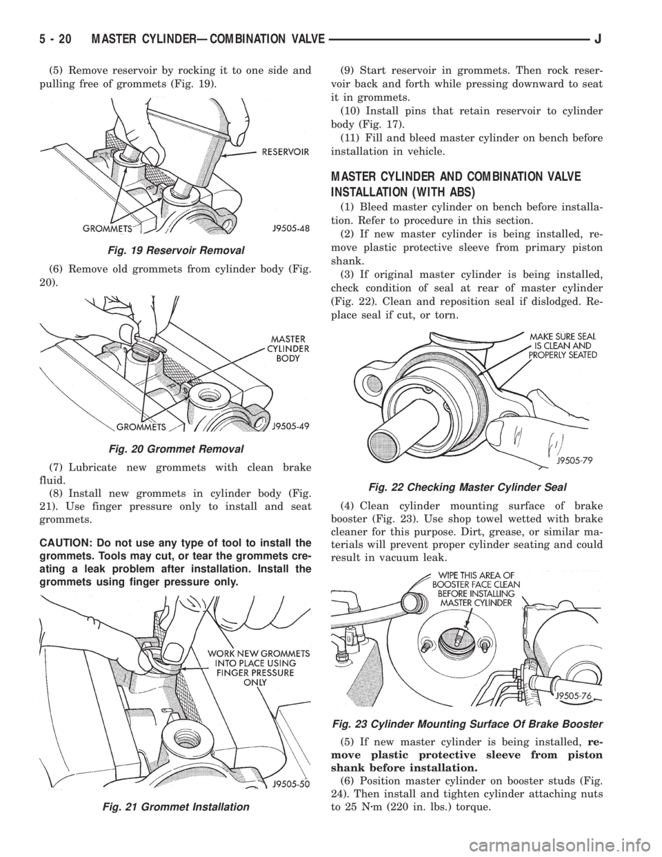
(5) Remove reservoir by rocking it to one side and
pulling free of grommets (Fig. 19).
(6) Remove old grommets from cylinder body (Fig.
20).
(7) Lubricate new grommets with clean brake
fluid.
(8) Install new grommets in cylinder body (Fig.
21). Use finger pressure only to install and seat
grommets.
CAUTION: Do not use any type of tool to install the
grommets. Tools may cut, or tear the grommets cre-
ating a leak problem after installation. Install the
grommets using finger pressure only.(9) Start reservoir in grommets. Then rock reser-
voir back and forth while pressing downward to seat
it in grommets.
(10) Install pins that retain reservoir to cylinder
body (Fig. 17).
(11) Fill and bleed master cylinder on bench before
installation in vehicle.
MASTER CYLINDER AND COMBINATION VALVE
INSTALLATION (WITH ABS)
(1) Bleed master cylinder on bench before installa-
tion. Refer to procedure in this section.
(2) If new master cylinder is being installed, re-
move plastic protective sleeve from primary piston
shank.
(3) If original master cylinder is being installed,
check condition of seal at rear of master cylinder
(Fig. 22). Clean and reposition seal if dislodged. Re-
place seal if cut, or torn.
(4) Clean cylinder mounting surface of brake
booster (Fig. 23). Use shop towel wetted with brake
cleaner for this purpose. Dirt, grease, or similar ma-
terials will prevent proper cylinder seating and could
result in vacuum leak.
(5) If new master cylinder is being installed,re-
move plastic protective sleeve from piston
shank before installation.
(6) Position master cylinder on booster studs (Fig.
24). Then install and tighten cylinder attaching nuts
to 25 Nzm (220 in. lbs.) torque.
Fig. 19 Reservoir Removal
Fig. 20 Grommet Removal
Fig. 21 Grommet Installation
Fig. 22 Checking Master Cylinder Seal
Fig. 23 Cylinder Mounting Surface Of Brake Booster
5 - 20 MASTER CYLINDERÐCOMBINATION VALVEJ
Page 173 of 2158
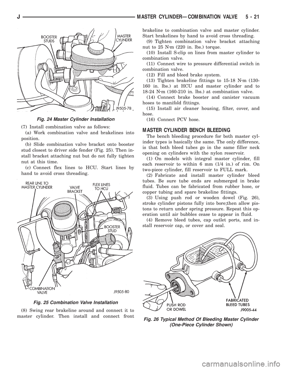
(7) Install combination valve as follows:
(a) Work combination valve and brakelines into
position.
(b) Slide combination valve bracket onto booster
stud closest to driver side fender (Fig. 25). Then in-
stall bracket attaching nut but do not fully tighten
nut at this time.
(c) Connect flex lines to HCU. Start lines by
hand to avoid cross threading.
(8) Swing rear brakeline around and connect it to
master cylinder. Then install and connect frontbrakeline to combination valve and master cylinder.
Start brakelines by hand to avoid cross threading.
(9) Tighten combination valve bracket attaching
nut to 25 Nzm (220 in. lbs.) torque.
(10) Install S-clip on lines from master cylinder to
combination valve.
(11) Connect wire to pressure differential switch in
combination valve.
(12) Fill and bleed brake system.
(13) Tighten brakeline fittings to 15-18 Nzm (130-
160 in. lbs.) at HCU and master cylinder and to
18-24 Nzm (160-210 in. lbs.) at combination valve.
(14) Connect brake booster and canister vacuum
hoses to manifold fittings.
(15) Install air cleaner housing, filter, cover, and
hose.
(16) Connect PCV hose.MASTER CYLINDER BENCH BLEEDING
The bench bleeding procedure for both master cyl-
inder types is basically the same. The only difference,
is that both bleed tubes go in the same filler neck
opening on cylinders with the nylon reservoir.
(1) On models with integral master cylinder, fill
each reservoir to within 6 mm (1/4 in.) of rim. On
two-piece cylinder, fill reservoir to FULL mark.
(2) Fabricate and install master cylinder bleed
tubes. Be sure tube ends are submerged in brake
fluid. Tubes can be fabricated from rubber hose, or
copper tubing and spare brakeline fittings.
(3) Using push rod or wooden dowel (Fig. 26),
stroke cylinder pistons fully into bore;then allow pis-
tons to return under spring pressure. Repeat this op-
eration until air bubbles cease to appear in fluid.
(4) Remove bleed tubes, cap outlet ports, and in-
stall reservoir cap, or cover and seal.
Fig. 24 Master Cylinder Installation
Fig. 25 Combination Valve Installation
Fig. 26 Typical Method Of Bleeding Master Cylinder
(One-Piece Cylinder Shown)
JMASTER CYLINDERÐCOMBINATION VALVE 5 - 21
Page 180 of 2158
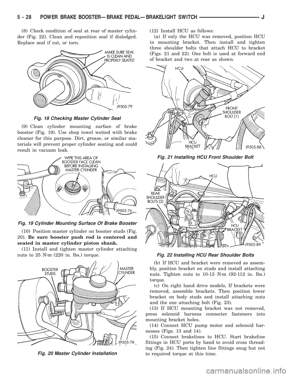
(8) Check condition of seal at rear of master cylin-
der (Fig. 22). Clean and reposition seal if dislodged.
Replace seal if cut, or torn.
(9) Clean cylinder mounting surface of brake
booster (Fig. 19). Use shop towel wetted with brake
cleaner for this purpose. Dirt, grease, or similar ma-
terials will prevent proper cylinder seating and could
result in vacuum leak.
(10) Position master cylinder on booster studs (Fig.
20).Be sure booster push rod is centered and
seated in master cylinder piston shank.
(11) Install and tighten master cylinder attaching
nuts to 25 Nzm (220 in. lbs.) torque.(12) Install HCU as follows:
(a) If only the HCU was removed, position HCU
in mounting bracket. Then install and tighten
three shoulder bolts that attach HCU to bracket
(Figs. 21 and 22). One bolt is used at forward end
of bracket and two at rear as shown.
(b) If HCU and bracket were removed as assem-
bly, position bracket on studs and install attaching
nuts. Tighten nuts to 10-13 Nzm (92-112 in. lbs.)
torque.
(c) On right hand drive models, If brackets were
removed, assemble brackets. Then position lower
bracket on body studs and install attaching nuts
and the one attaching bolt (Fig. 23).
(13) If HCU mounting bracket was not removed,
press solenoid harness connecter fasteners into
mounting bracket holes.
(14) Connect HCU pump motor and solenoid har-
nesses (Figs. 13 and 14).
(15) Connect brakelines to HCU. Start brakeline
fittings in HCU ports by hand to avoid cross thread-
ing (Fig. 24). Then tighten line fittings snug but not
to required torque at this time.
Fig. 18 Checking Master Cylinder Seal
Fig. 19 Cylinder Mounting Surface Of Brake Booster
Fig. 20 Master Cylinder Installation
Fig. 21 Installing HCU Front Shoulder Bolt
Fig. 22 Installing HCU Rear Shoulder Bolts
5 - 28 POWER BRAKE BOOSTERÐBRAKE PEDALÐBRAKELIGHT SWITCHJ