1995 JEEP YJ torque
[x] Cancel search: torquePage 233 of 2158

(4) Position clutch disc on flywheel. Be sure side of
disc marked flywheel side is positioned against fly-
wheel (Fig. 2). If disc is not marked, be sure flat side
of disc hub is toward flywheel.
(5) Inspect condition of pressure plate surface of
clutch cover (Fig. 2). Replace cover if this surface is
worn, heat checked, cracked, or scored.
(6) Insert clutch alignment tool in clutch disc (Fig.
3).
(7) Insert alignment tool in pilot bearing and posi-
tion disc on flywheel. Be sure disc hub is positioned
correctly. Side of hub marked Flywheel Side should
face flywheel (Fig. 2). If disc is not marked, place flat
side of disc against flywheel.
(8) Position clutch cover over disc and on flywheel
(Fig. 3).
(9) Install clutch cover bolts finger tight.(10) Tighten cover bolts evenly and in rotation a
few threads at a time.Cover bolts must be tight-
ened evenly and to specified torque to avoid
distorting cover. Tightening torques are 31 Nzm
(23 ft. lbs.) on 2.5L engines and 54 Nzm (40 ft.
lbs.) on 4.0L engines.
(11) Apply light coat of Mopar high temperature
bearing grease to pilot bearing hub and splines of
transmission input shaft.Do not overlubricate
shaft splines. This will result in grease contam-
ination of disc.
(12) Install transmission (Figs. 4 and 5). Refer to
procedures in Group 21.
RELEASE BEARING REPLACEMENT
(1) Remove transmission as described in Group 21.
Fig. 2 Clutch Disc And Pressure Plate InspectionFig. 3 Typical Method Of Aligning Clutch Disc
Fig. 4 Manual Transmission Mounting (4.0L)
JCLUTCH SERVICE 6 - 11
Page 235 of 2158
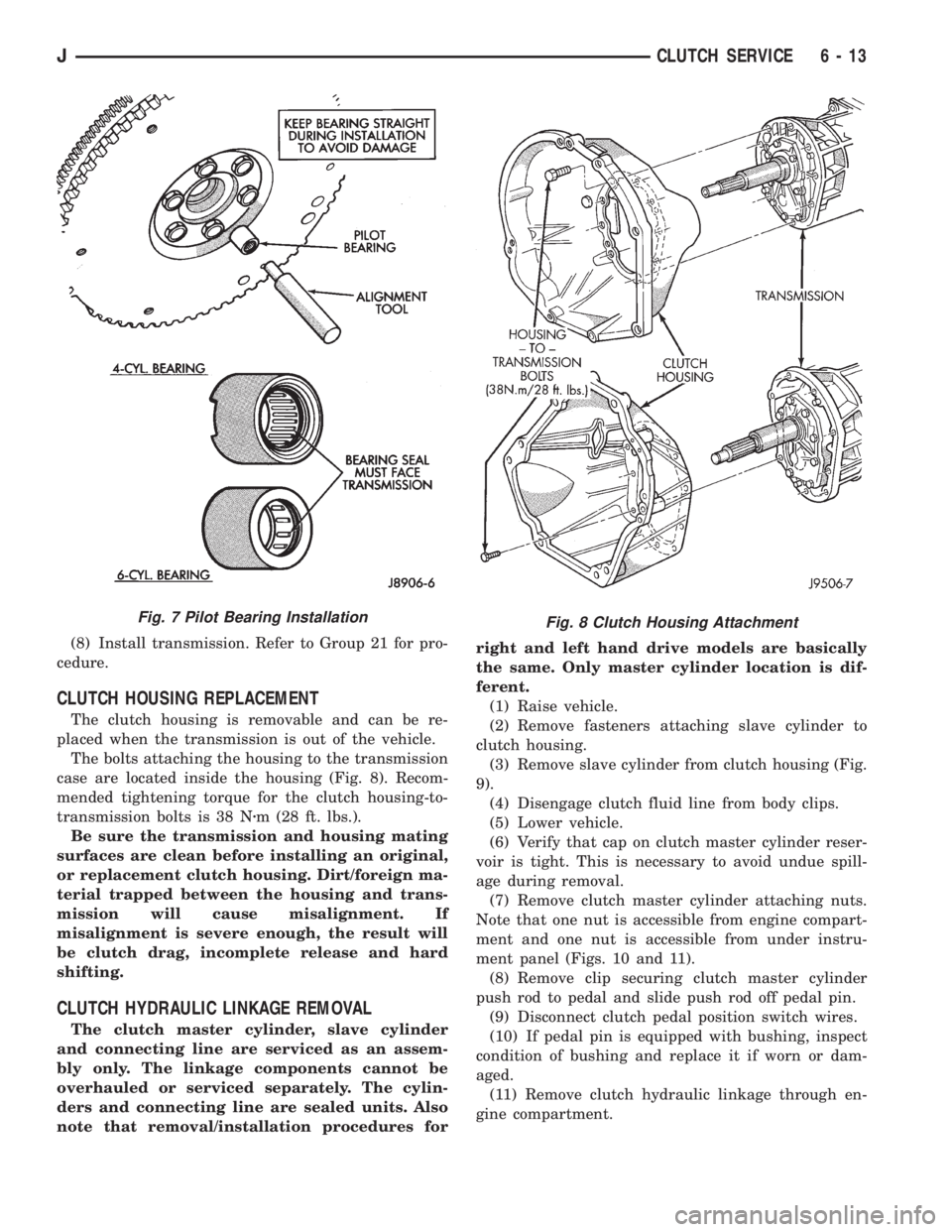
(8) Install transmission. Refer to Group 21 for pro-
cedure.
CLUTCH HOUSING REPLACEMENT
The clutch housing is removable and can be re-
placed when the transmission is out of the vehicle.
The bolts attaching the housing to the transmission
case are located inside the housing (Fig. 8). Recom-
mended tightening torque for the clutch housing-to-
transmission bolts is 38 Nzm (28 ft. lbs.).
Be sure the transmission and housing mating
surfaces are clean before installing an original,
or replacement clutch housing. Dirt/foreign ma-
terial trapped between the housing and trans-
mission will cause misalignment. If
misalignment is severe enough, the result will
be clutch drag, incomplete release and hard
shifting.
CLUTCH HYDRAULIC LINKAGE REMOVAL
The clutch master cylinder, slave cylinder
and connecting line are serviced as an assem-
bly only. The linkage components cannot be
overhauled or serviced separately. The cylin-
ders and connecting line are sealed units. Also
note that removal/installation procedures forright and left hand drive models are basically
the same. Only master cylinder location is dif-
ferent.
(1) Raise vehicle.
(2) Remove fasteners attaching slave cylinder to
clutch housing.
(3) Remove slave cylinder from clutch housing (Fig.
9).
(4) Disengage clutch fluid line from body clips.
(5) Lower vehicle.
(6) Verify that cap on clutch master cylinder reser-
voir is tight. This is necessary to avoid undue spill-
age during removal.
(7) Remove clutch master cylinder attaching nuts.
Note that one nut is accessible from engine compart-
ment and one nut is accessible from under instru-
ment panel (Figs. 10 and 11).
(8) Remove clip securing clutch master cylinder
push rod to pedal and slide push rod off pedal pin.
(9) Disconnect clutch pedal position switch wires.
(10) If pedal pin is equipped with bushing, inspect
condition of bushing and replace it if worn or dam-
aged.
(11) Remove clutch hydraulic linkage through en-
gine compartment.
Fig. 8 Clutch Housing AttachmentFig. 7 Pilot Bearing Installation
JCLUTCH SERVICE 6 - 13
Page 236 of 2158
CLUTCH HYDRAULIC LINKAGE INSTALLATION
(1) Be sure reservoir cover on clutch master cylin-
der is tight to avoid spills.
(2) Position clutch linkage components in vehicle.
Work connecting line and slave cylinder downward
past engine and adjacent to clutch housing.
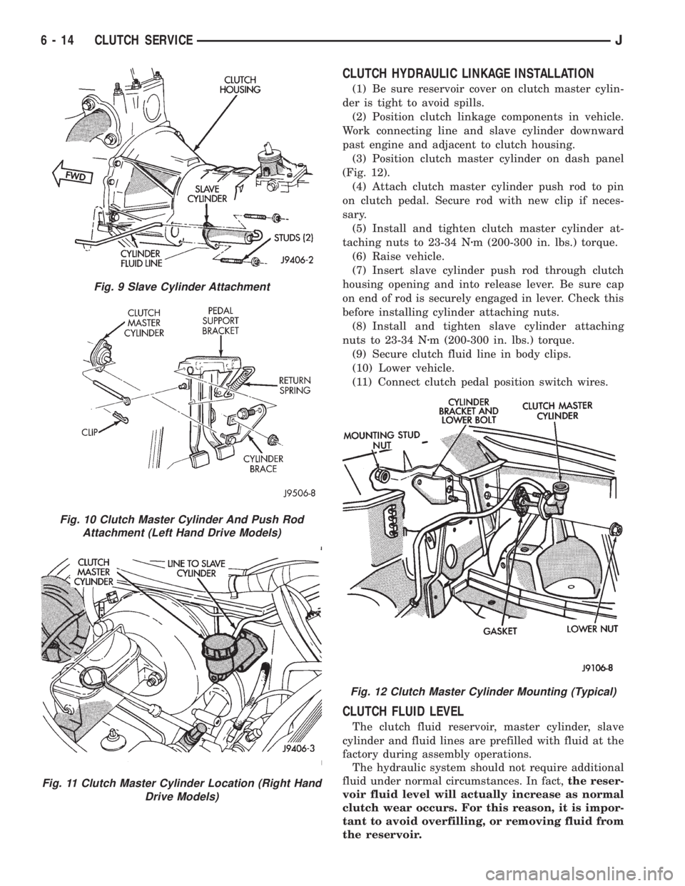
(3) Position clutch master cylinder on dash panel
(Fig. 12).
(4) Attach clutch master cylinder push rod to pin
on clutch pedal. Secure rod with new clip if neces-
sary.
(5) Install and tighten clutch master cylinder at-
taching nuts to 23-34 Nzm (200-300 in. lbs.) torque.
(6) Raise vehicle.
(7) Insert slave cylinder push rod through clutch
housing opening and into release lever. Be sure cap
on end of rod is securely engaged in lever. Check this
before installing cylinder attaching nuts.
(8) Install and tighten slave cylinder attaching
nuts to 23-34 Nzm (200-300 in. lbs.) torque.
(9) Secure clutch fluid line in body clips.
(10) Lower vehicle.
(11) Connect clutch pedal position switch wires.
CLUTCH FLUID LEVEL
The clutch fluid reservoir, master cylinder, slave
cylinder and fluid lines are prefilled with fluid at the
factory during assembly operations.
The hydraulic system should not require additional
fluid under normal circumstances. In fact,the reser-
voir fluid level will actually increase as normal
clutch wear occurs. For this reason, it is impor-
tant to avoid overfilling, or removing fluid from
the reservoir.
Fig. 9 Slave Cylinder Attachment
Fig. 10 Clutch Master Cylinder And Push Rod
Attachment (Left Hand Drive Models)
Fig. 11 Clutch Master Cylinder Location (Right Hand
Drive Models)
Fig. 12 Clutch Master Cylinder Mounting (Typical)
6 - 14 CLUTCH SERVICEJ
Page 238 of 2158
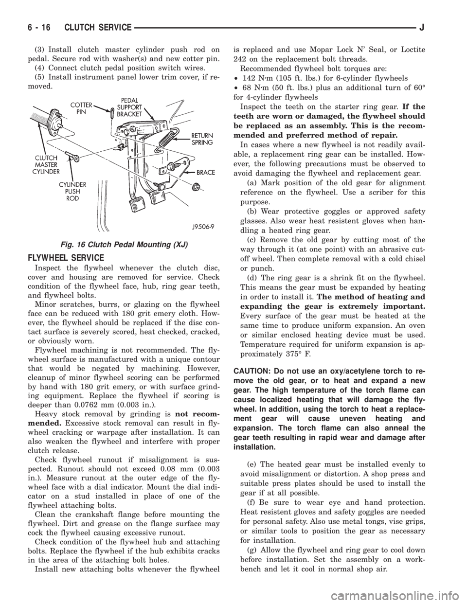
(3) Install clutch master cylinder push rod on
pedal. Secure rod with washer(s) and new cotter pin.
(4) Connect clutch pedal position switch wires.
(5) Install instrument panel lower trim cover, if re-
moved.
FLYWHEEL SERVICE
Inspect the flywheel whenever the clutch disc,
cover and housing are removed for service. Check
condition of the flywheel face, hub, ring gear teeth,
and flywheel bolts.
Minor scratches, burrs, or glazing on the flywheel
face can be reduced with 180 grit emery cloth. How-
ever, the flywheel should be replaced if the disc con-
tact surface is severely scored, heat checked, cracked,
or obviously worn.
Flywheel machining is not recommended. The fly-
wheel surface is manufactured with a unique contour
that would be negated by machining. However,
cleanup of minor flywheel scoring can be performed
by hand with 180 grit emery, or with surface grind-
ing equipment. Replace the flywheel if scoring is
deeper than 0.0762 mm (0.003 in.).
Heavy stock removal by grinding isnot recom-
mended.Excessive stock removal can result in fly-
wheel cracking or warpage after installation. It can
also weaken the flywheel and interfere with proper
clutch release.
Check flywheel runout if misalignment is sus-
pected. Runout should not exceed 0.08 mm (0.003
in.). Measure runout at the outer edge of the fly-
wheel face with a dial indicator. Mount the dial indi-
cator on a stud installed in place of one of the
flywheel attaching bolts.
Clean the crankshaft flange before mounting the
flywheel. Dirt and grease on the flange surface may
cock the flywheel causing excessive runout.
Check condition of the flywheel hub and attaching
bolts. Replace the flywheel if the hub exhibits cracks
in the area of the attaching bolt holes.
Install new attaching bolts whenever the flywheelis replaced and use Mopar Lock N' Seal, or Loctite
242 on the replacement bolt threads.
Recommended flywheel bolt torques are:
²142 Nzm (105 ft. lbs.) for 6-cylinder flywheels
²68 Nzm (50 ft. lbs.) plus an additional turn of 60É
for 4-cylinder flywheels
Inspect the teeth on the starter ring gear.If the
teeth are worn or damaged, the flywheel should
be replaced as an assembly. This is the recom-
mended and preferred method of repair.
In cases where a new flywheel is not readily avail-
able, a replacement ring gear can be installed. How-
ever, the following precautions must be observed to
avoid damaging the flywheel and replacement gear.
(a) Mark position of the old gear for alignment
reference on the flywheel. Use a scriber for this
purpose.
(b) Wear protective goggles or approved safety
glasses. Also wear heat resistent gloves when han-
dling a heated ring gear.
(c) Remove the old gear by cutting most of the
way through it (at one point) with an abrasive cut-
off wheel. Then complete removal with a cold chisel
or punch.
(d) The ring gear is a shrink fit on the flywheel.
This means the gear must be expanded by heating
in order to install it.The method of heating and
expanding the gear is extremely important.
Every surface of the gear must be heated at the
same time to produce uniform expansion. An oven
or similar enclosed heating device must be used.
Temperature required for uniform expansion is ap-
proximately 375É F.
CAUTION: Do not use an oxy/acetylene torch to re-
move the old gear, or to heat and expand a new
gear. The high temperature of the torch flame can
cause localized heating that will damage the fly-
wheel. In addition, using the torch to heat a replace-
ment gear will cause uneven heating and
expansion. The torch flame can also anneal the
gear teeth resulting in rapid wear and damage after
installation.
(e) The heated gear must be installed evenly to
avoid misalignment or distortion. A shop press and
suitable press plates should be used to install the
gear if at all possible.
(f) Be sure to wear eye and hand protection.
Heat resistent gloves and safety goggles are needed
for personal safety. Also use metal tongs, vise grips,
or similar tools to position the gear as necessary
for installation.
(g) Allow the flywheel and ring gear to cool down
before installation. Set the assembly on a work-
bench and let it cool in normal shop air.
Fig. 16 Clutch Pedal Mounting (XJ)
6 - 16 CLUTCH SERVICEJ
Page 239 of 2158
CAUTION: Do not use water, or compressed air to
cool the flywheel. The rapid cooling produced by
water or compressed air can distort, or crack the
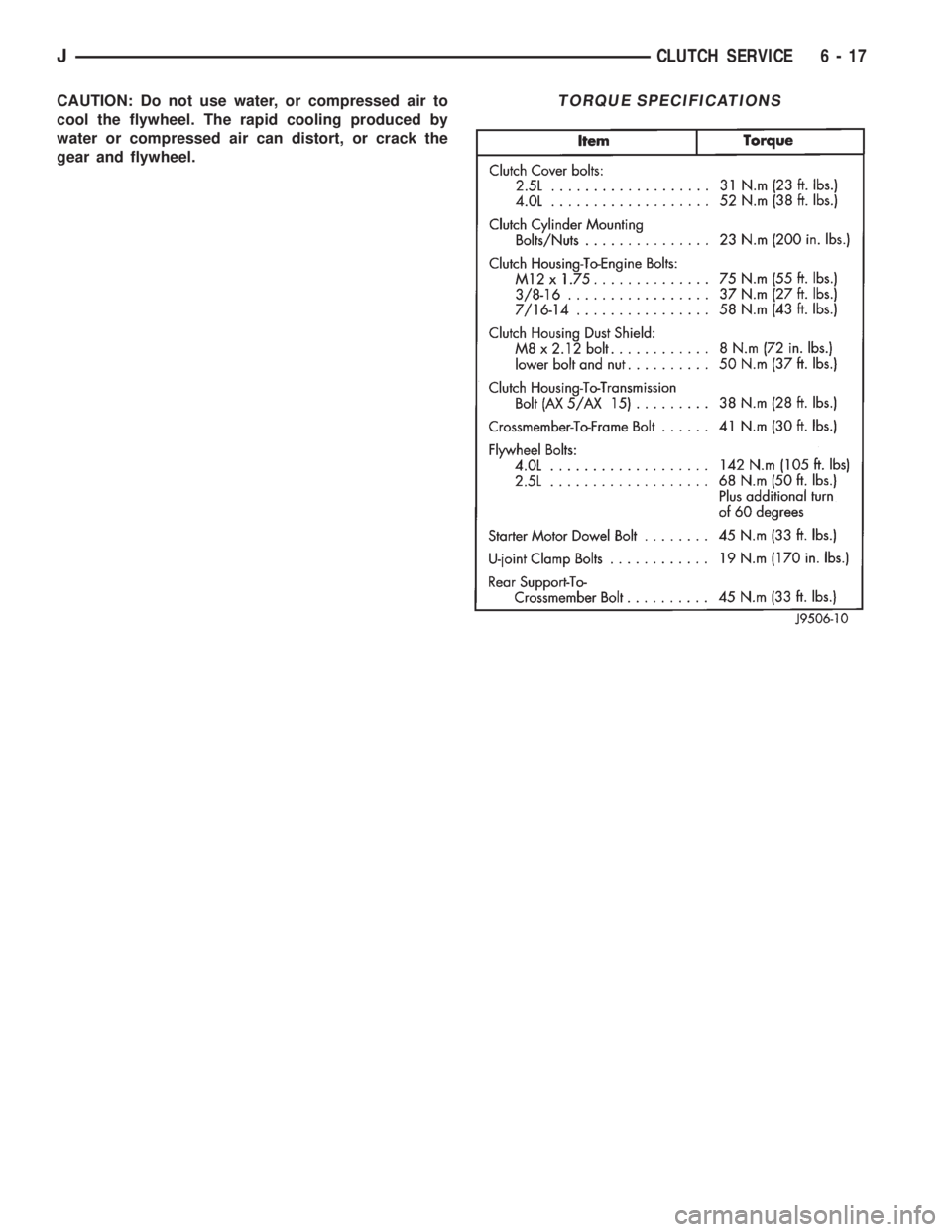
gear and flywheel.TORQUE SPECIFICATIONS
JCLUTCH SERVICE 6 - 17
Page 256 of 2158
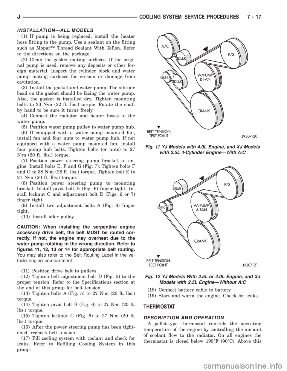
INSTALLATIONÐALL MODELS
(1) If pump is being replaced, install the heater
hose fitting to the pump. Use a sealant on the fitting
such as MoparŸ Thread Sealant With Teflon. Refer
to the directions on the package.
(2) Clean the gasket mating surfaces. If the origi-
nal pump is used, remove any deposits or other for-
eign material. Inspect the cylinder block and water
pump mating surfaces for erosion or damage from
cavitation.
(3) Install the gasket and water pump. The silicone
bead on the gasket should be facing the water pump.
Also, the gasket is installed dry. Tighten mounting
bolts to 30 Nzm (22 ft. lbs.) torque. Rotate the shaft
by hand to be sure it turns freely.
(4) Connect the radiator and heater hoses to the
water pump.
(5) Position water pump pulley to water pump hub.
(6) If equipped with a water pump mounted fan,
install fan and four nuts to water pump hub. If not
equipped with a water pump mounted fan, install
four pump hub bolts. Tighten bolts (or nuts) to 27
Nzm (20 ft. lbs.) torque.
(7) Position power steering pump bracket to en-
gine. Install bolts E, F and G (Fig. 7). Tighten bolts F
andGto38Nzm (28 ft. lbs.) torque. Tighten bolt E to
27 Nzm (20 ft. lbs.) torque.
(8) Position power steering pump to mounting
bracket. Install pivot bolt B (Fig. 6) finger tight. In-
stall locknut C and adjustment bolt D (Figs. 6 or 7)
finger tight.
(9) Install two adjustment bolts A (Fig. 6) finger
tight.
(10) Install idler pulley.
CAUTION: When installing the serpentine engine
accessory drive belt, the belt MUST be routed cor-
rectly. If not, the engine may overheat due to the
water pump rotating in the wrong direction. Refer to
figures 11, 12, 13 or 14 for appropriate belt routing.
You may also refer to the Belt Routing Label in the ve-
hicle engine compartment.
(11) Position drive belt to pulleys.
(12) Tighten belt adjustment bolt D (Fig. 5) to the
proper tension. Refer to the Specifications section at
the end of this group for belt tension.
(13) Tighten bolts A (Fig. 5) to 27 Nzm (20 ft. lbs.)
torque.
(14) Tighten pivot bolt B (Fig. 6) to 27 Nzm (20 ft.
lbs.) torque.
(15) Tighten locknut C (Fig. 6) to 27 Nzm (20 ft.
lbs.) torque.
(16) After the power steering pump has been tight-
ened, recheck belt tension.
(17) Fill cooling system with coolant and check for
leaks. Refer to Refilling Cooling System in this
group.(18) Connect battery cable to battery.
(19) Start and warm the engine. Check for leaks.
THERMOSTAT
DESCRIPTION AND OPERATION
A pellet-type thermostat controls the operating
temperature of the engine by controlling the amount
of coolant flow to the radiator. On all engines the
thermostat is closed below 195ÉF (90ÉC). Above this
Fig. 11 YJ Models with 4.0L Engine, and XJ Models
with 2.5L 4-Cylinder EngineÐWith A/C
Fig. 12 YJ Models With 2.5L or 4.0L Engine, and XJ
Models with 2.5L EngineÐWithout A/C
JCOOLING SYSTEM SERVICE PROCEDURES 7 - 17
Page 258 of 2158

INSTALLATION
(1) Install the replacement thermostat so that the
pellet, which is encircled by a coil spring, faces the
engine. All thermostats are marked on the outer
flange to indicate the proper installed position.
(a) Observe the recess groove in the engine cylin-
der head (Fig. 18).
(b) Position thermostat into this groove with ar-
row and air bleed hole on outer flange pointing up.
(2) Install replacement gasket and thermostat
housing.
CAUTION: Tightening the thermostat housing un-
evenly or with the thermostat out of its recess may
result in a cracked housing.(3) Tighten the housing bolts to 20 Nzm (15 ft. lbs.)
torque.
(4) Install hoses to thermostat housing.
(5) Install electrical connector to coolant tempera-
ture sensor.
(6) Be sure that the radiator draincock is tightly
closed. Fill the cooling system to the correct level
with the required coolant mixture. Refer to Refilling
Cooling System in this group.
(7) Start and warm the engine. Check for leaks.
Fig. 15 Hose Clamp ToolÐTypical
Fig. 16 Clamp Number/Letter Location
Fig. 17 Thermostat Removal/Installation
Fig. 18 Thermostat Recess
JCOOLING SYSTEM SERVICE PROCEDURES 7 - 19
Page 266 of 2158

WARNING: CONSTANT TENSION HOSE CLAMPS
ARE USED ON MOST COOLING SYSTEM HOSES.
WHEN REMOVING OR INSTALLING, USE ONLY
TOOLS DESIGNED FOR SERVICING THIS TYPE OF
CLAMP, SUCH AS SPECIAL CLAMP TOOL (NUMBER
6094) (FIG. 27). SNAP-ON CLAMP TOOL (NUMBER
HPC-20) MAY BE USED FOR LARGER CLAMPS. AL-
WAYS WEAR SAFETY GLASSES WHEN SERVICING
CONSTANT TENSION CLAMPS.
CAUTION: A number or letter is stamped into the
tongue of constant tension clamps (Fig. 28). If re-
placement is necessary, use only an original equip-
ment clamp with matching number or letter.XJ MODELS WITH 2.5L 4-CYLINDER ENGINE
REMOVAL
(1) Disconnect negative battery cable at battery.
(2) Observe the previousWARNINGS.Remove ra-
diator cap.
(3) Position drain pan under draincock. Open radi-
ator draincock. Drain radiator.
(4) Remove radiator upper and lower hose clamps
(Figs. 27 and 28). Remove hoses.
(5) Remove E-clip from alignment dowel at radia-
tor lower mounting bracket (Fig. 29).
(6) Disconnect coolant reserve/overflow tank hose
from radiator.
(7) Remove four radiator fan shroud mounting
bolts (Fig. 29). Push shroud back against front of en-
gine.
(8) If equipped, disconnect and plug automatic
transmission fluid cooler lines. Refer to Group 21,
Transmission for procedures.
(9) Remove two radiator top mounting bolts (Fig.
29).
(10) (a) If equipped with air conditioning, remove
the radiator grille mounting screws and remove grill.
Refer to Group 23, Body for procedures.
(b) If equipped, remove the air conditioning con-
denser-to-radiator mounting bolt. Use an open end
wrench to remove bottom bolts (Fig. 30).
(11) Lift radiator straight up and out of vehicle.
Take care not to damage radiator fins. When remov-
ing radiator, note position of the rubber seals located
on the top, bottom and sides of radiator (Fig. 29). To
prevent possible overheating, these seals must be in-
stalled to their original positions.
INSTALLATION
(1) Install radiator behind air conditioning con-
denser with bottom alignment dowel inserted into ra-
diator lower mounting bracket (Fig. 29).
(2) Install E-clip to radiator alignment dowel (Fig.
29).
(3) Tighten the four condenser-to-radiator mount-
ing bolts to 6.2 Nzm (55 in. lbs.) torque.
(4) If removed, install radiator grille.
(5) Tighten radiator top mounting bolts to 6 Nzm
(55 in. lbs.) torque.
(6) If equipped, connect automatic transmission
fluid cooler lines to radiator. Refer to Group 21,
Transmission for procedures.
(7) Install the radiator fan shroud.
(8) Connect the coolant reserve/overflow tank hose.
(9) Connect radiator hoses and install hose clamps.
(10) Connect negative battery cable.
(11) Close the draincock.
(12) Fill cooling system with correct coolant.
(13) Install radiator cap.
(14) Check and adjust automatic transmission
fluid level (if equipped).
Fig. 27 Hose Clamp ToolÐTypical
Fig. 28 Clamp Number/Letter Location
JCOOLING SYSTEM SERVICE PROCEDURES 7 - 27