Page 351 of 2158
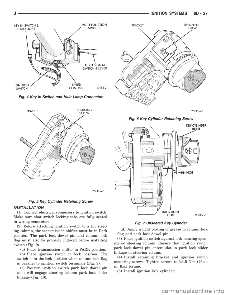
INSTALLATION
(1) Connect electrical connectors to ignition switch.
Make sure that switch locking tabs are fully seated
in wiring connectors.
(2) Before attaching ignition switch to a tilt steer-
ing column, the transmission shifter must be in Park
position. The park lock dowel pin and column lock
flag must also be properly indexed before installing
switch (Fig. 9).
(a) Place transmission shifter in PARK position.
(b) Place ignition switch in lock position. The
switch is in the lock position when column lock flag
is parallel to ignition switch terminals (Fig. 9).
(c) Position ignition switch park lock dowel pin
so it will engage steering column park lock slider
linkage (Fig. 10).(d) Apply a light coating of grease to column lock
flag and park lock dowel pin.
(3) Place ignition switch against lock housing open-
ing on steering column. Ensure that ignition switch
park lock dowel pin enters slot in park lock slider
linkage in steering column.
(4) Install retaining bracket and ignition switch
mounting screws. Tighten screws to 36.5 Nzm (2664
in. lbs.) torque.
(5) Install ignition lock cylinder:
Fig. 4 Key-In-Switch and Halo Lamp Connector
Fig. 5 Key Cylinder Retaining Screw
Fig. 6 Key Cylinder Retaining Screw
Fig. 7 Unseated Key Cylinder
JIGNITION SYSTEMS 8D - 27
Page 352 of 2158
(a) With lock cylinder and ignition switch in
Lock position, insert lock cylinder into ignition
switch until it bottoms.(b) Insert ignition key into lock cylinder. While
gently pushing lock cylinder in toward ignition
switch, rotate ignition key to end of travel.
(6) Install retaining screw into bracket and lock
cylinder. Tighten screw to 36.5 Nzm (2664 in. lbs.)
torque.
(7) Install steering column covers. Tighten screws
to2Nzm (17 in. lbs.) torque.
(8) If vehicle is equipped with a tilt steering col-
umn, install tilt lever.
(9) Connect negative cable to battery.
(10) Check for proper operation of halo light, shift
lock (if applicable), and column lock. Also check for
proper operation of ignition switch accessory, lock,
off, run, and start positions.
Fig. 10 Ignition Switch Mounting PadFig. 8 Key Cylinder Removal
Fig. 9 Ignition Switch View From Column
8D - 28 IGNITION SYSTEMSJ
Page 355 of 2158
nition switch. Install screws finger tight. Remove the
dimmer switch actuator rod securing-tape from steer-
ing column.
(8) Adjust dimmer switch as follows: Depress the
switch slightly and insert a 3/32-inch drill bit into
the adjustment hole (Fig. 11). This is done to prevent
horizontal switch movement.
(9) Move switch toward steering wheel to remove
any lash from switch actuator rod. Tighten dimmer
and ignition switch fasteners to 4 Nzm (35 in. lbs.)
torque.(10) Install the windshield wiper intermittent con-
trol module and its bracket (if equipped).
(11) Install the negative battery cable.
Test dimmer switch. Test ignition switch operation
in all switch positions. If equipped with a tilt steer-
ing column, test operation of dimmer switch and ig-
nition switch in all tilt positions.
Fig. 14 Detent PositionsÐNon-Tilt Steering Column
Fig. 15 Detent PositionsÐTilt Steering Column
JIGNITION SYSTEMS 8D - 31
Page 356 of 2158
SPECIFICATIONS
GENERAL INFORMATION
The following specifications are published from the
latest information available at the time of publica-
tion.If anything differs between the specifica-
tions found on the Vehicle Emission Control
Information (VECI) label and the following
specifications, use specifications on VECI label.
The VECI label is located in the engine compart-
ment.
SPARK PLUGS
ENGINE FIRING ORDERÐ2.5L 4-CYLINDER
ENGINE
ENGINE FIRING ORDERÐ4.0L 6-CYLINDER
ENGINE
TORQUE
8D - 32 IGNITION SYSTEMSJ
Page 440 of 2158
SERVICE PROCEDURES - XJ
WINDSHIELD WIPER MOTOR REMOVE/INSTALL
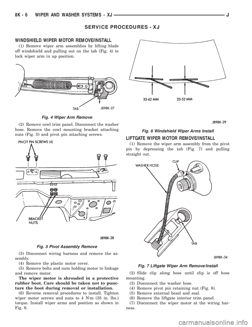
(1) Remove wiper arm assemblies by lifting blade
off windshield and pulling out on the tab (Fig. 4) to
lock wiper arm in up position.
(2) Remove cowl trim panel. Disconnect the washer
hose. Remove the cowl mounting bracket attaching
nuts (Fig. 5) and pivot pin attaching screws.
(3) Disconnect wiring harness and remove the as-
sembly.
(4) Remove the plastic motor cover.
(5) Remove bolts and nuts holding motor to linkage
and remove motor.
The wiper motor is shrouded in a protective
rubber boot. Care should be taken not to punc-
ture the boot during removal or installation.
(6) Reverse removal procedures to install. Tighten
wiper motor screws and nuts to 4 Nzm (35 in. lbs.)
torque. Install wiper arms and position as shown in
Fig. 6.
LIFTGATE WIPER MOTOR REMOVE/INSTALL
(1) Remove the wiper arm assembly from the pivot
pin by depressing the tab (Fig. 7) and pulling
straight out.
(2) Slide clip along hose until clip is off hose
mounting.
(3) Disconnect the washer hose.
(4) Remove pivot pin retaining nut (Fig. 8).
(5) Remove external bezel and seal.
(6) Remove the liftgate interior trim panel.
(7) Disconnect the wiper motor at the wiring har-
ness.
Fig. 4 Wiper Arm Remove
Fig. 5 Pivot Assembly Remove
Fig. 6 Windshield Wiper Arms Install
Fig. 7 Liftgate Wiper Arm Remove/Install
8K - 6 WIPER AND WASHER SYSTEMS - XJJ
Page 458 of 2158
(36) Install a new switch and switch cover.
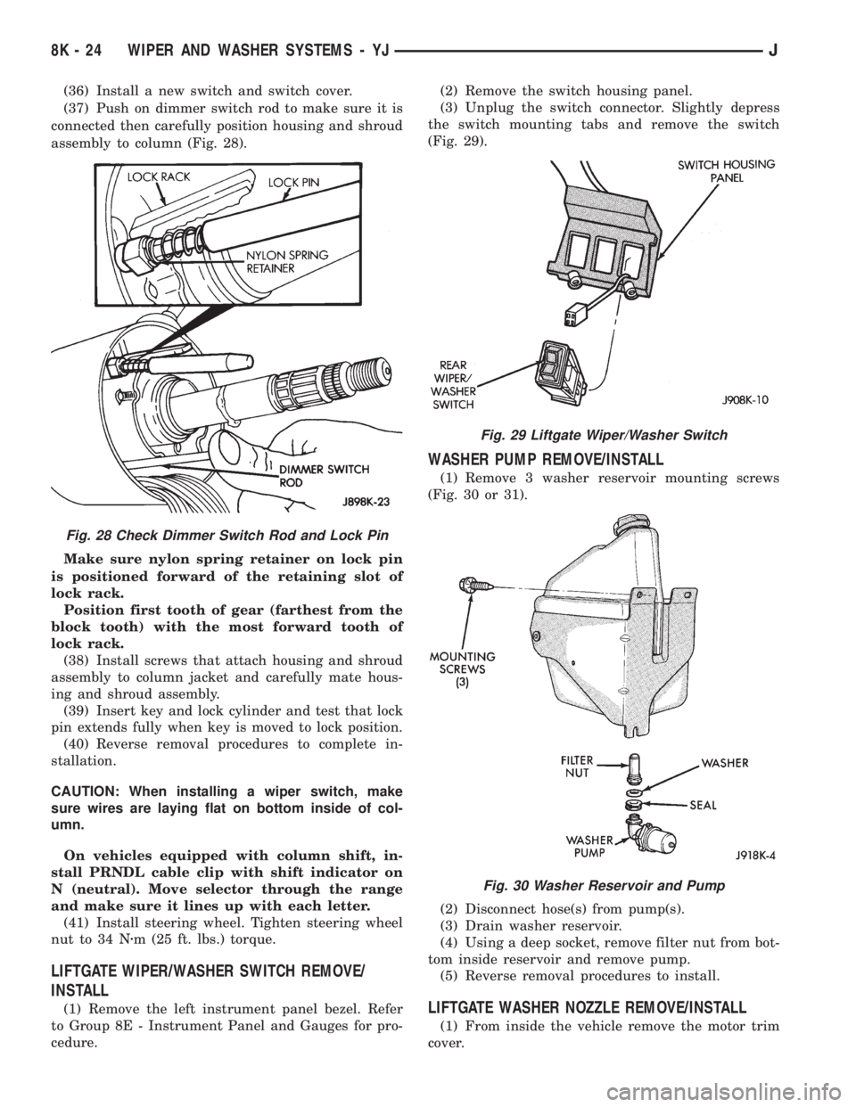
(37) Push on dimmer switch rod to make sure it is
connected then carefully position housing and shroud
assembly to column (Fig. 28).
Make sure nylon spring retainer on lock pin
is positioned forward of the retaining slot of
lock rack.
Position first tooth of gear (farthest from the
block tooth) with the most forward tooth of
lock rack.
(38) Install screws that attach housing and shroud
assembly to column jacket and carefully mate hous-
ing and shroud assembly.
(39) Insert key and lock cylinder and test that lock
pin extends fully when key is moved to lock position.
(40) Reverse removal procedures to complete in-
stallation.
CAUTION: When installing a wiper switch, make
sure wires are laying flat on bottom inside of col-
umn.
On vehicles equipped with column shift, in-
stall PRNDL cable clip with shift indicator on
N (neutral). Move selector through the range
and make sure it lines up with each letter.
(41) Install steering wheel. Tighten steering wheel
nut to 34 Nzm (25 ft. lbs.) torque.
LIFTGATE WIPER/WASHER SWITCH REMOVE/
INSTALL
(1) Remove the left instrument panel bezel. Refer
to Group 8E - Instrument Panel and Gauges for pro-
cedure.(2) Remove the switch housing panel.
(3) Unplug the switch connector. Slightly depress
the switch mounting tabs and remove the switch
(Fig. 29).
WASHER PUMP REMOVE/INSTALL
(1) Remove 3 washer reservoir mounting screws
(Fig. 30 or 31).
(2) Disconnect hose(s) from pump(s).
(3) Drain washer reservoir.
(4) Using a deep socket, remove filter nut from bot-
tom inside reservoir and remove pump.
(5) Reverse removal procedures to install.
LIFTGATE WASHER NOZZLE REMOVE/INSTALL
(1) From inside the vehicle remove the motor trim
cover.
Fig. 28 Check Dimmer Switch Rod and Lock Pin
Fig. 29 Liftgate Wiper/Washer Switch
Fig. 30 Washer Reservoir and Pump
8K - 24 WIPER AND WASHER SYSTEMS - YJJ
Page 471 of 2158
INSTALLATION
(1) Squeeze the tabs on the side of the fog lamp
switch and insert the switch in the instrument panel
cavity.
(2) Connect the wire harness connector to the
switch.
(3) Install the fog lamp switch cover.
(4) Position the bezel on the instrument panel and
install the attaching screws. Tighten the screws se-
curely.
MULTI-FUNCTION SWITCH SERVICE
PROCEDURESÐXJ
REMOVAL
(1) Disconnect battery negative cable.
(2) Remove lower instrument panel screws along
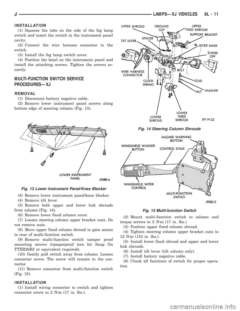
bottom edge of steering column (Fig. 13).
(3) Remove lower instrument panel/knee blocker.
(4) Remove tilt lever.
(5) Remove both upper and lower lock shrouds
from column (Fig. 14).
(6) Remove lower fixed column cover.
(7) Loosen steering column upper bracket nuts. Do
not remove nuts.
(8) Move upper fixed column shroud to gain access
to rear of multi-function switch.
(9) Remove multi-function switch tamper proof
mounting screws (tamperproof torx bit Snap On
TTXR20B2 or equivalent required).
(10) Gently pull switch away from column. Loosen
connector screw. The screw will remain in the con-
nector.
(11) Remove connector from multi-function switch
(Fig. 15).
INSTALLATION
(1) Install wiring connector to switch and tighten
connector screw to 2 Nzm (17 in. lbs.).(2) Mount multi-function switch to column and
torque screws to 2 Nzm (17 in. lbs.).
(3) Position upper fixed column shroud.
(4) Tighten steering column upper bracket nuts to
12 Nzm (110 in. lbs.).
(5) Install lower fixed shroud and upper and lower
lock shrouds.
(6) Install tilt lever (tilt column only).
(7) Install battery negative cable.
(8) Check all functions of switch for proper opera-
tion.
Fig. 13 Lower Instrument Panel/Knee Blocker
Fig. 14 Steering Column Shrouds
Fig. 15 Multi-function Switch
JLAMPSÐXJ VEHICLES 8L - 11
Page 487 of 2158
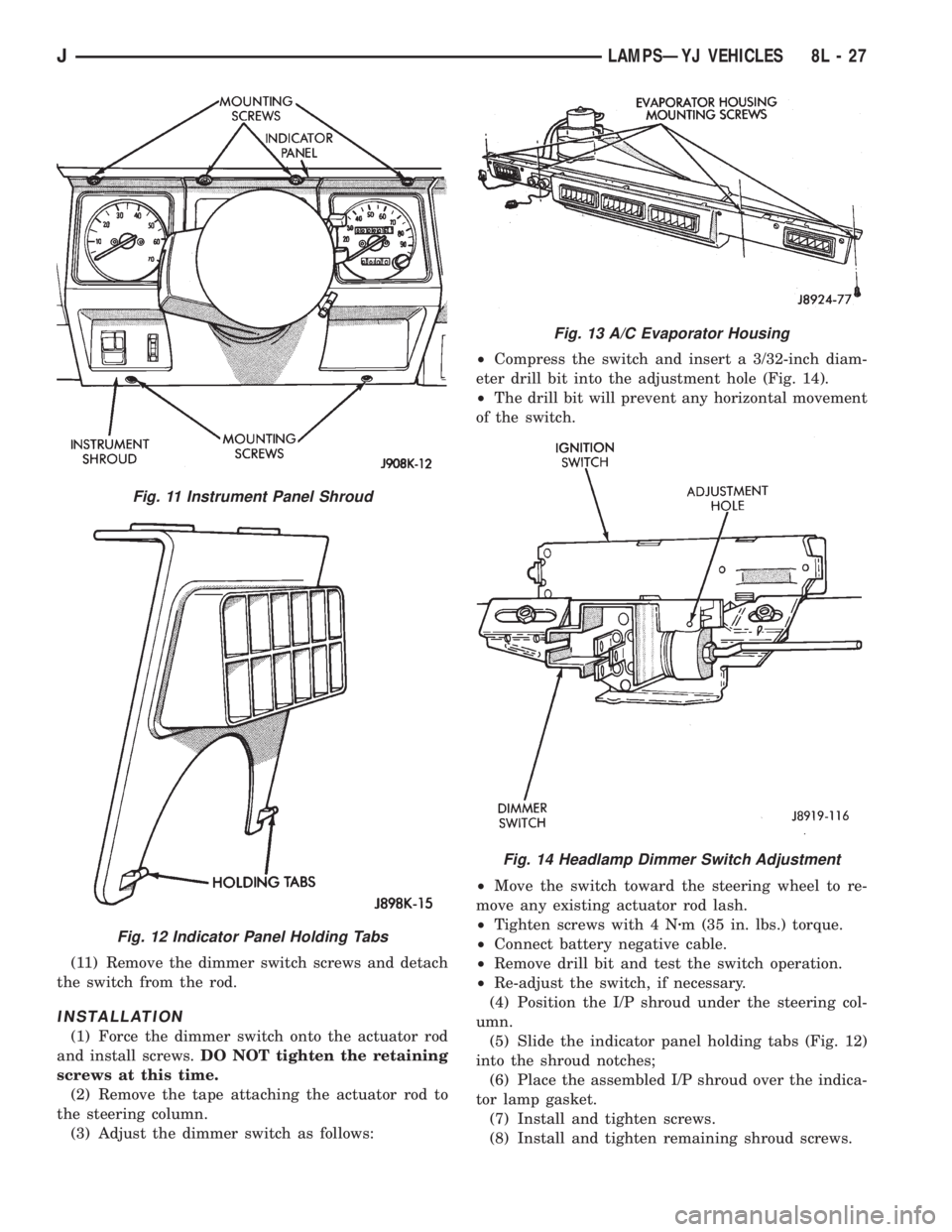
(11) Remove the dimmer switch screws and detach
the switch from the rod.
INSTALLATION
(1) Force the dimmer switch onto the actuator rod
and install screws.DO NOT tighten the retaining
screws at this time.
(2) Remove the tape attaching the actuator rod to
the steering column.
(3) Adjust the dimmer switch as follows:²Compress the switch and insert a 3/32-inch diam-
eter drill bit into the adjustment hole (Fig. 14).
²The drill bit will prevent any horizontal movement
of the switch.
²Move the switch toward the steering wheel to re-
move any existing actuator rod lash.
²Tighten screws with 4 Nzm (35 in. lbs.) torque.
²Connect battery negative cable.
²Remove drill bit and test the switch operation.
²Re-adjust the switch, if necessary.
(4) Position the I/P shroud under the steering col-
umn.
(5) Slide the indicator panel holding tabs (Fig. 12)
into the shroud notches;
(6) Place the assembled I/P shroud over the indica-
tor lamp gasket.
(7) Install and tighten screws.
(8) Install and tighten remaining shroud screws.
Fig. 11 Instrument Panel Shroud
Fig. 12 Indicator Panel Holding Tabs
Fig. 13 A/C Evaporator Housing
Fig. 14 Headlamp Dimmer Switch Adjustment
JLAMPSÐYJ VEHICLES 8L - 27