1995 JEEP YJ torque
[x] Cancel search: torquePage 495 of 2158

DEPLOYED
Following an airbag deployment, the vehicle inte-
rior will contain a powdery residue. This residue is
primarily sodium bicarbonate (baking soda), used as
an airbag cushion lubricant. However, there will also
be traces of sodium hydroxide powder, a chemical
byproduct of the generant used for airbag deploy-
ment. Since this powder can irritate the skin, eyes,
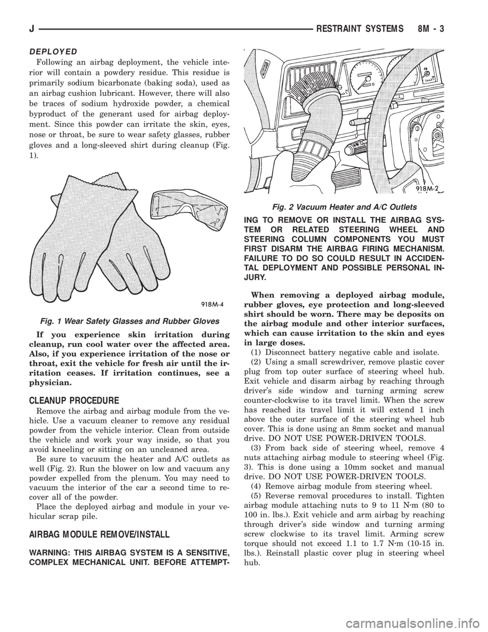
nose or throat, be sure to wear safety glasses, rubber
gloves and a long-sleeved shirt during cleanup (Fig.
1).
If you experience skin irritation during
cleanup, run cool water over the affected area.
Also, if you experience irritation of the nose or
throat, exit the vehicle for fresh air until the ir-
ritation ceases. If irritation continues, see a
physician.
CLEANUP PROCEDURE
Remove the airbag and airbag module from the ve-
hicle. Use a vacuum cleaner to remove any residual
powder from the vehicle interior. Clean from outside
the vehicle and work your way inside, so that you
avoid kneeling or sitting on an uncleaned area.
Be sure to vacuum the heater and A/C outlets as
well (Fig. 2). Run the blower on low and vacuum any
powder expelled from the plenum. You may need to
vacuum the interior of the car a second time to re-
cover all of the powder.
Place the deployed airbag and module in your ve-
hicular scrap pile.
AIRBAG MODULE REMOVE/INSTALL
WARNING: THIS AIRBAG SYSTEM IS A SENSITIVE,
COMPLEX MECHANICAL UNIT. BEFORE ATTEMPT-ING TO REMOVE OR INSTALL THE AIRBAG SYS-
TEM OR RELATED STEERING WHEEL AND
STEERING COLUMN COMPONENTS YOU MUST
FIRST DISARM THE AIRBAG FIRING MECHANISM.
FAILURE TO DO SO COULD RESULT IN ACCIDEN-
TAL DEPLOYMENT AND POSSIBLE PERSONAL IN-
JURY.
When removing a deployed airbag module,
rubber gloves, eye protection and long-sleeved
shirt should be worn. There may be deposits on
the airbag module and other interior surfaces,
which can cause irritation to the skin and eyes
in large doses.
(1) Disconnect battery negative cable and isolate.
(2) Using a small screwdriver, remove plastic cover
plug from top outer surface of steering wheel hub.
Exit vehicle and disarm airbag by reaching through
driver's side window and turning arming screw
counter-clockwise to its travel limit. When the screw
has reached its travel limit it will extend 1 inch
above the outer surface of the steering wheel hub
cover. This is done using an 8mm socket and manual
drive. DO NOT USE POWER-DRIVEN TOOLS.
(3) From back side of steering wheel, remove 4
nuts attaching airbag module to steering wheel (Fig.
3). This is done using a 10mm socket and manual
drive. DO NOT USE POWER-DRIVEN TOOLS.
(4) Remove airbag module from steering wheel.
(5) Reverse removal procedures to install. Tighten
airbag module attaching nuts to 9 to 11 Nzm (80 to
100 in. lbs.). Exit vehicle and arm airbag by reaching
through driver's side window and turning arming
screw clockwise to its travel limit. Arming screw
torque should not exceed 1.1 to 1.7 Nzm (10-15 in.
lbs.). Reinstall plastic cover plug in steering wheel
hub.
Fig. 1 Wear Safety Glasses and Rubber Gloves
Fig. 2 Vacuum Heater and A/C Outlets
JRESTRAINT SYSTEMS 8M - 3
Page 515 of 2158

SERVICE PROCEDURES
POWER SEAT SWITCH REMOVE/INSTALL
(1) Disconnect battery negative cable.
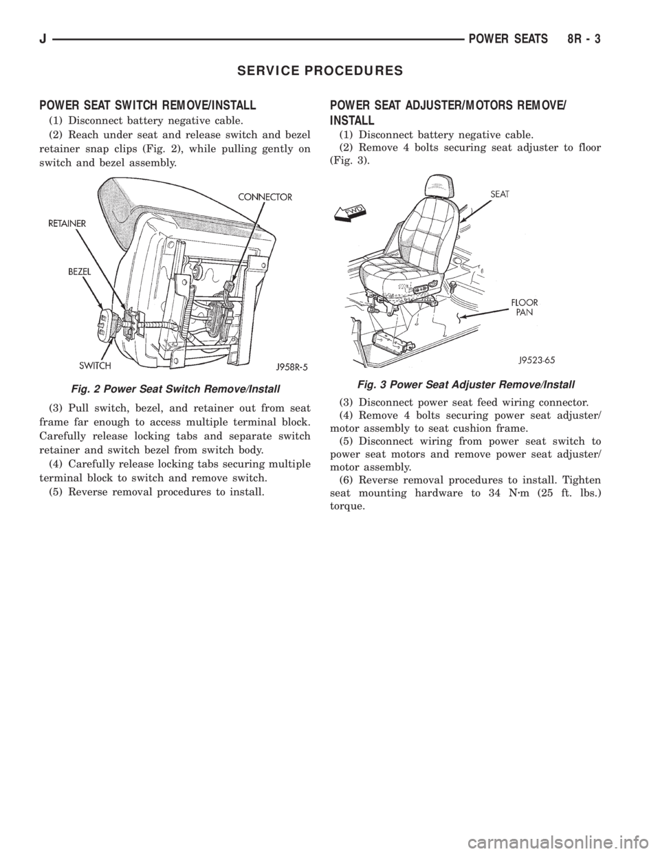
(2) Reach under seat and release switch and bezel
retainer snap clips (Fig. 2), while pulling gently on
switch and bezel assembly.
(3) Pull switch, bezel, and retainer out from seat
frame far enough to access multiple terminal block.
Carefully release locking tabs and separate switch
retainer and switch bezel from switch body.
(4) Carefully release locking tabs securing multiple
terminal block to switch and remove switch.
(5) Reverse removal procedures to install.
POWER SEAT ADJUSTER/MOTORS REMOVE/
INSTALL
(1) Disconnect battery negative cable.
(2) Remove 4 bolts securing seat adjuster to floor
(Fig. 3).
(3) Disconnect power seat feed wiring connector.
(4) Remove 4 bolts securing power seat adjuster/
motor assembly to seat cushion frame.
(5) Disconnect wiring from power seat switch to
power seat motors and remove power seat adjuster/
motor assembly.
(6) Reverse removal procedures to install. Tighten
seat mounting hardware to 34 Nzm (25 ft. lbs.)
torque.
Fig. 2 Power Seat Switch Remove/InstallFig. 3 Power Seat Adjuster Remove/Install
JPOWER SEATS 8R - 3
Page 524 of 2158

(13) Pull glass to the full up position and tape
glass to door.
(14) Disconnect wire harness connector from the
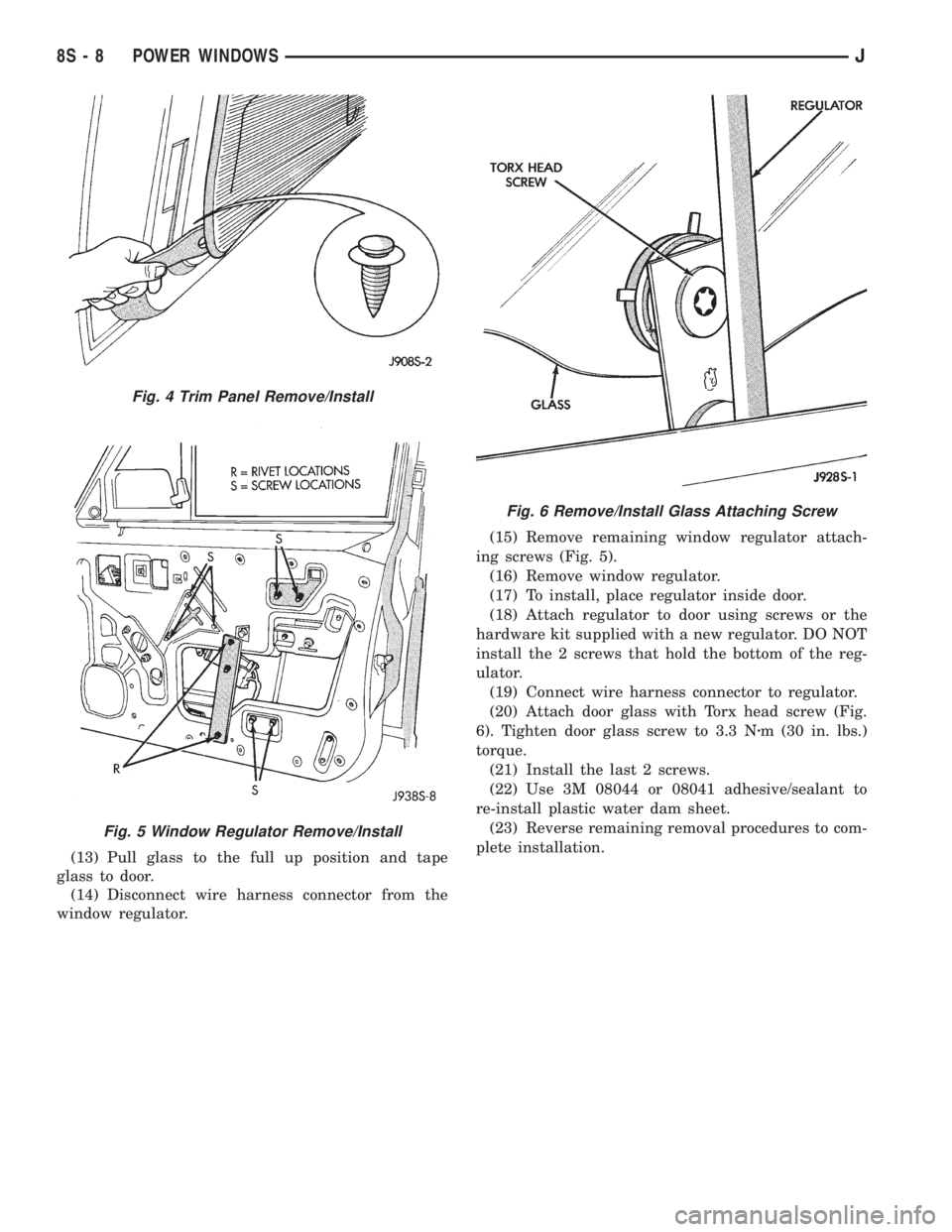
window regulator.(15) Remove remaining window regulator attach-
ing screws (Fig. 5).
(16) Remove window regulator.
(17) To install, place regulator inside door.
(18) Attach regulator to door using screws or the
hardware kit supplied with a new regulator. DO NOT
install the 2 screws that hold the bottom of the reg-
ulator.
(19) Connect wire harness connector to regulator.
(20) Attach door glass with Torx head screw (Fig.
6). Tighten door glass screw to 3.3 Nzm (30 in. lbs.)
torque.
(21) Install the last 2 screws.
(22) Use 3M 08044 or 08041 adhesive/sealant to
re-install plastic water dam sheet.
(23) Reverse remaining removal procedures to com-
plete installation.
Fig. 4 Trim Panel Remove/Install
Fig. 5 Window Regulator Remove/Install
Fig. 6 Remove/Install Glass Attaching Screw
8S - 8 POWER WINDOWSJ
Page 557 of 2158

POWER DISTRIBUTION
GENERAL INFORMATION
This section covers the Power Distribution Center
(PDC) and all circuits involved with it. For additional
information on system operation, refer to the appro-
priate section of the wiring diagrams.
DIAGRAM INDEX
Component Page
A/C Compressor Clutch Relay..............8W-11-3, 11
ABS Control Module.....................8W-11-6, 7
ABS Power Relay......................8W-11-3, 6
ABS Pump Motor Relay..................8W-11-3, 7
Automatic Shut Down Relay................8W-11-3, 9
Chime/Buzzer Module..................8W-11-10, 14
Circuit Breaker Cavity 16 (Fuse Block)..........8W-11-13
Combination Flasher......................8W-11-17
Daytime Running Lamp Module.............8W-11-5, 10
Diode D101............................8W-11-6
Engine Starter Motor Relay................8W-11-3, 4
Fuel Pump Relay.......................8W-11-3, 8
Fuse 1 (PDC)..........................8W-11-13
Fuse 3 (PDC)..........................8W-11-12
Fuse 4 (Fuse Block)......................8W-11-14
Fuse 4 (PDC)..........................8W-11-15
Fuse 5 (PDC)..........................8W-11-14
Fuse 6 (PDC)....................8W-11-4, 7, 10, 15
Fuse 7 (Fuse Block).......................8W-11-7
Fuse 7 (PDC)...........................8W-11-4
Fuse 8 (PDC)...........................8W-11-7
Fuse 9 (Fuse Block)......................8W-11-12
Fuse 9 (PDC)..........................8W-11-13
Fuse 10 (PDC)........................8W-11-6, 8
Fuse 11 (Fuse Block).....................8W-11-13
Fuse 11 (PDC).........................8W-11-10
Fuse 12 (PDC).........................8W-11-15Component Page
Fuse 13 (PDC)..........................8W-11-4
Fuse 14 (PDC)..........................8W-11-8
Fuse 15 (Fuse Block).....................8W-11-14
Fuse 15 (PDC)..........................8W-11-8
Fuse 16 (PDC).........................8W-11-12
Fuse 17 (Fuse Block).....................8W-11-10
Headlamp Delay Module.................8W-11-10, 14
Headlamp Switch........................8W-11-14
Headlamp Dimmer Switch..................8W-11-14
Horn Rear Window Relay..................8W-11-17
Horn Relay............................8W-11-17
Ignition Switch...................8W-11-4, 7, 10, 15
In-Line Circuit Breaker (Stop Lamp Relay)........8W-11-13
LCD Illumination Relay....................8W-11-17
Overhead Console.....................8W-11-10, 14
Powertrain Control Module..........8W-11-4, 5, 8, 9, 11
Power Distribution Center...................8W-11-2
Power Door Lock Relay...................8W-11-16
Power Door Unlock Relay..................8W-11-16
Radiator Fan Control Relay................8W-11-3, 11
Remote Keyless Entry Module.............8W-11-10, 12
Relay Center...........................8W-11-16
Telltale Connector (I.P. Cluster)..........8W-11-6, 10, 12
Torque Converter Clutch (TCC) Relay...........8W-11-15
Transmission Control Module...............8W-11-5, 8
J8W-11 POWER DISTRIBUTIONÐXJ VEHICLES 8W - 11 - 1
Page 589 of 2158

FUEL/IGNITION
INDEX
page page
Automatic Shut Down (ASD) Relay............. 1
Battery Feed.............................. 1
Brake Switch Input......................... 5
Camshaft Position Sensor.................... 3
CCDBus ................................ 5
Crankshaft Position Sensor................... 3
Data Link Connector........................ 5
Diagram Index Ð2.5L Engine.................. 6
Diagram Index Ð4.0L Engine.................. 6
Engine Coolant Temperature Sensor............ 3
Extended Idle Switch....................... 5
Fuel Injectors............................. 1
Fuel Pump Module......................... 2
Fuel Pump Relay.......................... 2
Heated Oxygen Sensor...................... 3Idle Air Control (IAC) Motor................... 2
Ignition Coil.............................. 2
Ignition Switch............................ 1
Intake Air Temperature Sensor................ 4
Malfunction Indicator Lamp (MIL)............... 5
Manifold Absolute Pressure Sensor............. 4
Park/Neutral Position Switch.................. 4
Power (Device) Ground...................... 5
Power Steering Pressure Switch............... 5
Tachometer Signal......................... 5
Throttle Position Sensor..................... 4
Torque Converter Clutch (TCC) Solenoid and
Relay................................. 4
Upshift Lamp............................. 5
Vehicle Speed Sensor....................... 2
IGNITION SWITCH
Circuit A1 from fuse 11 in the power distribution
center (PDC), supplies battery voltage to the ignition
switch. Depending upon position, the ignition switch
powers circuits A21, A38, A41, or A48.
START POSITION
In the START position, the ignition switch connects
circuit A1 to circuit A41. Circuit A41 connects to the
coil side of the starter motor relay.
Additionally in the START position, the case
grounded ignition switch provides ground for the
brake lamp switch and the warning lamps in the
instrument cluster.
START OR RUN POSITION
In the START or RUN position, the ignition switch
connects circuit A1 to circuit A21. Circuit A21 splices
to power fuse 17 in the fuse block and the coil side of
the Automatic Shut Down (ASD) relay and the fuel
pump relay.
RUN (ONLY) POSITION
When the ignition switch is in the RUN position, it
connects circuit A1 to circuit A38. Circuit A22 splices
to power fuses 1 and 7 in the fuse block.
²Fuse 1 powers the rear wiper system on circuit
V15.
²Fuse 7 feeds the Anti-Lock Brake System (ABS) on
circuit 236.
ACCESSORY OR RUN POSITIONS
In the ACCESSORY or RUN positions, the ignition
switch connects circuit A1 to circuit A48. Circuit A48
connects to a bus bar in the fuse block that feeds
fuses 2, 5, and 8.
AUTOMATIC SHUT DOWN (ASD) RELAY
When the ignition switch is in either the START or
RUN positions, it connects circuit A1 from fuse 6 in
the Power Distribution Center (PDC) to circuit A21.
Circuit A21 supplies battery voltage to the coil side of
the Automatic Shut Down (ASD) relay. The Power-
train Control Module (PCM) provides ground for the
relay on circuit K51. Circuit K51 connects to cavity 51
of the PCM.
When the PCM grounds the ASD relay, contacts
inside the relay close and connect circuit A18 from
fuse 14 in the PDC to circuit A142. Circuit A142
splices to the generator field terminal, fuel injectors,
and ignition coil. Circuit A142 also connects to cavity
57 of the PCM.
HELPFUL INFORMATION
²Along with supplying voltage to the coil side of the
ASD relay, circuit A21 also supplies voltage to the coil
side of the fuel pump relay.
BATTERY FEED
Circuit A14 from fuse 2 in the Power Distribution
Center (PDC) supplies battery voltage to cavity 3 of
the powertrain control module.
HELPFUL INFORMATION
Circuit A14 also supplies power to the contact sides
of the fuel pump relay and fuse F2 in the PDC. Fuse
F2 powers circuit A18 which supplies voltage to the
contact side of the automatic shut down relay.
FUEL INJECTORS
When the Automatic Shut Down (ASD) relay con-
tacts close, they connect circuits A14 and A142. Cir-
J8W-30 FUEL/IGNITIONÐXJ VEHICLES 8W - 30 - 1
Page 592 of 2158

The PCM provides a ground for the engine coolant
temperature sensor signal (circuit K2) through circuit
K4. Circuit K4 connects to cavity 4 of the PCM con-
nector.
HELPFUL INFORMATION
Circuit K4 splices to supply ground for the signals
from the following:
²Heated oxygen sensor
²Camshaft position sensor
²Crankshaft position sensor
²Intake air temperature sensor
²Throttle position sensor
²Manifold absolute pressure sensor
²Engine coolant temperature sensor
²Vehicle speed sensor
THROTTLE POSITION SENSOR
From the Powertrain Control Module (PCM), cir-
cuit K6 supplies 5 volts to the throttle position sen-
sor (TPS). Circuit K6 connects to cavity 6 of the
PCM.
Circuit K22 delivers the TPS signal to the PCM.
Circuit K22 connects to cavity 22 of the PCM.
The PCM provides a ground for the throttle posi-
tion sensor signal (circuit K22) through circuit K4.
Circuit K4 connects to cavity 4 of the PCM.
HELPFUL INFORMATION
Refer to Group 14 for throttle position sensor oper-
ation.
Circuit K6 splices to supply 5 volts to the manifold
absolute pressure sensor.
On vehicles equipped with the 4.0L engine and au-
tomatic transmission, circuit K22 splices to the
transmission control module.
Circuit K4 splices to supply ground for the signals
from the following:
²Heated oxygen sensor
²Camshaft position sensor
²Crankshaft position sensor
²Intake air temperature sensor
²Throttle position sensor
²Manifold absolute pressure sensor
²Engine coolant temperature sensor
²Vehicle speed sensor
MANIFOLD ABSOLUTE PRESSURE SENSOR
From the Powertrain Control Module (PCM), cir-
cuit K6 supplies 5 volts to the manifold absolute
pressure (MAP) sensor. Circuit K6 connects to cavity
6 of the PCM.
Circuit K1 delivers the MAP signal to the PCM.
Circuit K1 connects to cavity 1 of the PCM.
The PCM provides a ground for the MAP sensor
signal (circuit K1) through circuit K4. Circuit K4 con-
nects to cavity 4 of the PCM.
HELPFUL INFORMATION
Refer to Group 14 for MAP sensor operation.
Circuit K6 splices to supply 5 volts to the throttle
position sensor.
Circuit K4 splices to supply ground for the signals
from the following:
²Heated oxygen sensor
²Camshaft position sensor
²Crankshaft position sensor
²Intake air temperature sensor
²Throttle position sensor
²Manifold absolute pressure sensor
²Engine coolant temperature sensor
²Vehicle speed sensor
INTAKE AIR TEMPERATURE SENSOR
The intake air temperature sensor provides an in-
put to the Powertrain Control Module (PCM) on cir-
cuit K21. Circuit K21 connects to cavity 21 of the
PCM.
From circuit K21, the intake air temperature sen-
sor draws voltage from the PCM. The sensor is a
variable resistor. As intake air temperature changes,
the resistance in the sensor changes, causing a
change in current draw.
The PCM provides a ground for the intake air tem-
perature sensor signal (circuit K21) through circuit
K4. Circuit K4 connects to cavity 4 of the PCM.
HELPFUL INFORMATION
Circuit K4 splices to supply ground for the signals
from the following:
²Heated oxygen sensor
²Camshaft position sensor
²Crankshaft position sensor
²Intake air temperature sensor
²Throttle position sensor
²Manifold absolute pressure sensor
²Engine coolant temperature sensor
²Vehicle speed sensor
PARK/NEUTRAL POSITION SWITCH
When closed, the case-grounded park/neutral posi-
tion switch provides a ground path on circuit T41 for
the coil side of the starter motor relay. Circuit A41
from the ignition switch provides battery voltage to
the coil side of the relay.
Circuit T41 splices to cavity 30 of the PCM. The
park/neutral position switch provides an input to the
Powertrain Control Module (PCM).
TORQUE CONVERTER CLUTCH (TCC) SOLENOID
AND RELAY
The TCC solenoid is only used on 2.5L engines
with the three-speed automatic transmissions. The
Powertrain Control Module (PCM) operates the TCC
solenoid by energizing the TCC relay.
8W - 30 - 4 8W-30 FUEL/IGNITIONÐXJ VEHICLESJ
Page 609 of 2158

TRANSMISSION CONTROLS
UPSHIFT LAMP
On vehicles equipped with a manual transmission,
the PCM grounds the up-shift lamp on circuit K54.
Circuit K54 connects to cavity 54 of the PCM.
FOUR-WHEEL DRIVE (4WD) SWITCH
When the 4WD switch closes, circuit Z1 provides
ground for the 4WD indicator lamp in the instrument
cluster. Circuit F87 connects to the instrument clus-
ter and supplies battery voltage to the 4WD indicator
lamp. Circuit 107 connects the indicator lamp to the
4WD switch. Circuit 106 connects the lamp to the in-
strument cluster and circuit F87.
TRANSMISSION CONTROL MODULEÐ4.0L
ENGINE ONLY
Vehicles equipped with the 4.0L engine have elec-
tronically controlled solenoids in the automatic trans-
mission valve body.
The Transmission Control Module (TCM) receives
inputs from the Throttle Position Sensor (TPS) on
circuit K22 and the stop lamp switch on circuit K29.
Circuit K4 connects to the TCM to provide ground for
the TPS signal. The TCM receives the transmission
output speed sensor signal on circuit T505. Circuit
A14 from fuse 2 in the Power Distribution Center
supplies battery voltage to the TCM. Circuit Z12 pro-
vides ground for the TCM.
The TCM powers the S1 solenoid on circuit T510,
the S2 solenoid on circuit T509, and the S3 solenoid
on circuit T508. Circuit Z12 provides ground for the
S1, S2, and S3 solenoids.
TORQUE CONVERTER CLUTCH (TCC) SOLENOID
AND RELAYÐ2.5L ENGINE ONLY
The TCC solenoid is only used on 2.5L engines
with the three-speed automatic transmissions. The
Powertrain Control Module (PCM) operates the TCC
solenoid by energizing the TCC relay.
Circuit T17 from fuse 12 in the Power Distribution
Center (PDC) supplies voltage to the coil and contact
sides of the TCC relay. When the PCM provides a
ground path on circuit K54 for the coil side of the re-
lay, the relay contacts close.
When the relay contacts close, they connect circuit
T17 with circuit T22. Circuit T22 supplies battery
voltage to the case grounded TCC solenoid. Circuit
K54 connects to PCM cavity 54.
HELPFUL INFORMATION
²In the RUN or START position, the ignition switch
connects circuit A1 from fuse 6 in the PDC to circuit
A21.
DIAGRAM INDEX
Component Page
4-WD Indicator Lamp......................8W-31-4
4-WD Indicator Switch.....................8W-31-4
Back-Up Lamp Switch.....................8W-31-3
Fuse 2 (PDC)...........................8W-31-4
Fuse 6 (PDC).........................8W-31-2, 3
Fuse 11 (PDC)..........................8W-31-3
Fuse 12 (PDC)..........................8W-31-2
Ignition Switch........................8W-31-2, 3
Powertrain Control Module..................8W-31-2
Park/Neutral Position Switch.................8W-31-3
TCC Relay.............................8W-31-2
TCC Solenoid...........................8W-31-2
Transmission Control Module.................8W-31-2
J8W-31 TRANSMISSION CONTROLSÐXJ VEHICLES 8W - 31 - 1
Page 1118 of 2158

CHARGING SYSTEM
CHARGING SYSTEM
The charging system is an integral part of the bat-
tery and starting systems. Because all these systems
work in conjunction, diagnose and test them together.
Circuit A11 connects to the generator output termi-
nal and splices to fuse 2 and fuse 6 in the Power Dis-
tribution Center (PDC). Circuit A0 connects the
battery to the PDC.
Circuit Z0 provides ground for the generator. Cir-
cuit Z0 attaches to the right side rear of the engine.
When the ignition switch is in either the START or
RUN position, it connects circuit A1 from fuse 4 in
the PDC to circuit A21. Circuit A21 powers fuse 5 in
the fuse block. Circuit G50 from fuse 5 splices to
power the coil side of the Automatic Shut Down
(ASD) relay. The Powertrain Control Module (PCM)
provides ground for the relay on circuit K51. Circuit
K51 connects to cavity 51 of the PCM.
When the PCM grounds the ASD relay, contacts in-
side the relay close and connect circuit A14 from fuse
1 in the PDC to circuit A142. Circuit A142 splices to
the generator field terminal.
The PCM has an internal voltage regulator that
controls generator output. The PCM controls the gen-
erator field on circuit K20. Circuit K20 connects to
PCM cavity 20.When the engine operates and there is current in
the generator field, the generator produces a B+ volt-
age. The generator supplies B+ voltage to the battery
through the A11 and A0 circuits.
HELPFUL INFORMATION
²The ignition switch also connects circuit A1 with
circuits A41, A22, and A31.
²Circuit A21 also powers fuse 9 in the fuse block.
²Circuit G50 also powers the coil sides of the fuel
pump relay and the torque convertor clutch (TCC) re-
lay.
²The ASD relay supplies battery voltage for the fuel
injectors, ignition coil, and the heated oxygen sensor.
²Circuit K51 also provides ground for the coil side
of the fuel pump relay.
DIAGRAM INDEX
Component Page
Battery...............................8W-20-2
Fuse 2 (PDC)...........................8W-20-2
Fuse 6 (PDC)...........................8W-20-2
Generator..............................8W-20-2
Powertrain Control Module (PCM)..............8W-20-2
J8W-20 CHARGING SYSTEMÐYJ VEHICLES 8W - 20 - 1