1995 JEEP YJ body panel removal
[x] Cancel search: body panel removalPage 178 of 2158
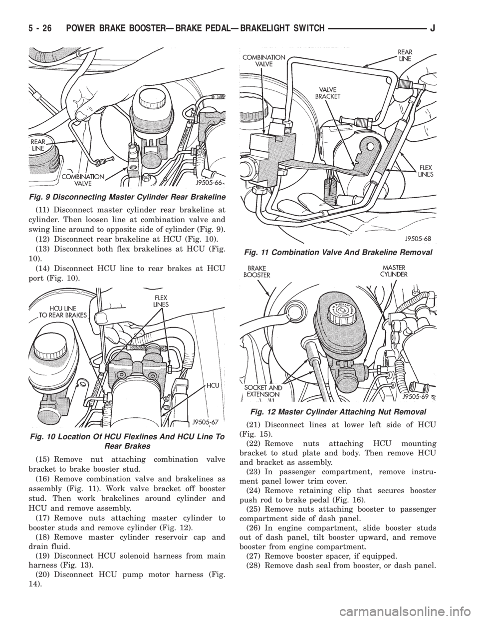
(11) Disconnect master cylinder rear brakeline at
cylinder. Then loosen line at combination valve and
swing line around to opposite side of cylinder (Fig. 9).
(12) Disconnect rear brakeline at HCU (Fig. 10).
(13) Disconnect both flex brakelines at HCU (Fig.
10).
(14) Disconnect HCU line to rear brakes at HCU
port (Fig. 10).
(15) Remove nut attaching combination valve
bracket to brake booster stud.
(16) Remove combination valve and brakelines as
assembly (Fig. 11). Work valve bracket off booster
stud. Then work brakelines around cylinder and
HCU and remove assembly.
(17) Remove nuts attaching master cylinder to
booster studs and remove cylinder (Fig. 12).
(18) Remove master cylinder reservoir cap and
drain fluid.
(19) Disconnect HCU solenoid harness from main
harness (Fig. 13).
(20) Disconnect HCU pump motor harness (Fig.
14).(21) Disconnect lines at lower left side of HCU
(Fig. 15).
(22) Remove nuts attaching HCU mounting
bracket to stud plate and body. Then remove HCU
and bracket as assembly.
(23) In passenger compartment, remove instru-
ment panel lower trim cover.
(24) Remove retaining clip that secures booster
push rod to brake pedal (Fig. 16).
(25) Remove nuts attaching booster to passenger
compartment side of dash panel.
(26) In engine compartment, slide booster studs
out of dash panel, tilt booster upward, and remove
booster from engine compartment.
(27) Remove booster spacer, if equipped.
(28) Remove dash seal from booster, or dash panel.
Fig. 9 Disconnecting Master Cylinder Rear Brakeline
Fig. 10 Location Of HCU Flexlines And HCU Line To
Rear Brakes
Fig. 11 Combination Valve And Brakeline Removal
Fig. 12 Master Cylinder Attaching Nut Removal
5 - 26 POWER BRAKE BOOSTERÐBRAKE PEDALÐBRAKELIGHT SWITCHJ
Page 190 of 2158

air gap should be 0.40 to 1.3 mm (0.0157 to 0.051
in.). If gap is incorrect, the sensor is either loose, or
damaged.
A rear sensor air gap adjustment is only needed
when reinstalling an original sensor. Replacement
sensors have an air gap spacer attached to the sensor
pickup face. The spacer establishes correct air gap
when pressed against the tone ring during installa-
tion. As the tone ring rotates, it peels the spacer off
the sensor to create the required air gap. Rear sensor
air gap is 0.92-1.45 mm (0.036-0.057 in.).
Sensor air gap measurement, or adjustment proce-
dures are provided in this section. Refer to the front,
or rear sensor removal and installation procedures as
required.
FRONT WHEEL SENSOR REMOVAL
(1) Raise vehicle and turn wheel outward for easier
access to sensor.
(2) Remove sensor wire from mounting brackets.
(3) Clean sensor and surrounding area with shop
towel before removal.
(4) Remove bolt attaching sensor to steering
knuckle and remove sensor.
(5) remove sensor wire from brackets on body and
steering knuckle.
(6) Unseat sensor wire grommet in wheel house
panel.
(7) In engine compartment, disconnect sensor wire
connector at harness plug. Then remove sensor and
wire.
FRONT WHEEL SENSOR INSTALLATION
(1) Iforiginalsensor will be installed, wipe all
traces of old spacer material off sensor pickup face.
Use a dry shop towel for this purpose.
(2) Apply Mopar Lock N' Seal or Loctite 242 to bolt
that secures sensor in steering knuckle. Use new
sensor bolt if original bolt is worn or damaged.
(3) Position sensor on steering knuckle. Seat sen-
sor locating tab in hole in knuckle and install sensor
attaching bolt finger tight.
(4) Tighten sensor attaching bolt to 14 Nzm (11 ft.
lbs.) torque.
(5) If original sensor has been installed, check sen-
sor air gap. Air gap should be 0.40 to 1.3 mm (0.0157
to 0.051 in.). If gap is incorrect, sensor is either loose,
or damaged.
(6) Secure sensor wire to steering knuckle and
body brackets.
(7) Route sensor wire forward and behind shock
absorber. Then attach sensor wire to spring seat
bracket with grommets on sensor wire.
(8) Route sensor wire to outer sill bracket. Remove
all twists or kinks from wire.
(9) Attach sensor wire to sill bracket with grom-
met. Be sure wire is free of twists and kinks.(10) Verify sensor wire routing. Wire should loop
forward and above sill bracket. Loose end of wire
should be below sill bracket and towards brake hose.
(11) Seat sensor wire grommet in body panel and
clip wire to brake line at grommet location.
(12) Connect sensor wire to harness in engine com-
partment.
REAR WHEEL SENSOR REMOVAL
(1) On XJ models, raise and fold rear seat forward
for access to rear sensor connectors (Fig. 9).
(2) Disconnect sensors at rear harness connectors.
(3) Push sensor grommets and sensor wires
through floorpan.
(4) Raise vehicle.
(5) Disconnect sensor wires at rear axle connectors.
(6) Remove wheel and tire assembly.
(7) Remove brake drum.
(8) Remove clips securing sensor wires to brake-
lines, rear axle and, brake hose.
(9) Unseat sensor wire support plate grommet.
(10) Remove bolt attaching sensor to bracket and
remove sensor.
REAR WHEEL SENSOR INSTALLATION AND
ADJUSTMENT
(1) Iforiginal sensoris being installed, remove
any remaining pieces of cardboard spacer from sen-
sor pickup face. Use dry shop towel only to remove
old spacer material.
(2) Insert sensor wire through support plate hole.
Then seat sensor grommet in support plate.
(3) Apply Mopar Lock N' Seal or Loctite 242 to
Fig. 9 Acceleration Switch And Rear Sensor
Connections (XJ)
5 - 38 ABS OPERATION AND SERVICEJ
Page 193 of 2158

(2) Align and attach harness connector to ECU.
Slide connector into engagement with tangs on ECU.
Then tilt connector downward and into engagement
with ECU pin terminals. Exercise care as pin termi-
nals can be damaged if connector is forced into place.
(3) Connect harness to security alarm module, if
equipped.
(4) Position ECU bracket under instrument panel.
(5) Install and tighten ECU mounting bracket
bolts/nuts to 8-14 Nzm (75- 125 in. lbs.) torque.
(6) Install trim panel on instrument panel, if re-
moved.
ECU REMOVAL/INSTALLATION (YJ MODELS)
The antilock ECU is attached to the dash panel in-
side the passenger compartment. It is positioned just
above the heater/air conditioning plenum housing, in
line with the glove box (Fig. 16).
The ECU is attached to the dash panel by bolts
and nuts that are accessible from the engine com-
partment. The fasteners are located just to the right
of the battery.
On models with air conditioning, it will be neces-
sary to remove the air conditioning fascia panel and
ducts for access to the ECU and harness connecter.
HCU REMOVAL (XJ)
A new design HCU is used in 1995 models. The
new HCU has built-in accumulators that store the
extra fluid released for antilock mode operation. As a
result, the master cylinder and HCU are no longer
interconnected by hoses.The 1995 and prior hy-
draulic control units are NOT interchangeable.
(1) Disconnect vent hoses at air cleaner cover.
(2) Loosen clamp securing air cleaner hose to in-
take manifold. Use screwdriver to tap clamp loose.
(3) Remove air cleaner cover and hose. Then re-
move air filter from air cleaner shell (Fig. 17).
(4) Remove two bolts and one nut that secure air
cleaner housing to body panel (Fig. 17).
(5) Remove air cleaner housing from engine com-
partment.
Fig. 16 ECU Location (YJ)
Fig. 17 Air Cleaner Components
JABS OPERATION AND SERVICE 5 - 41
Page 235 of 2158
(8) Install transmission. Refer to Group 21 for pro-
cedure.
CLUTCH HOUSING REPLACEMENT
The clutch housing is removable and can be re-
placed when the transmission is out of the vehicle.
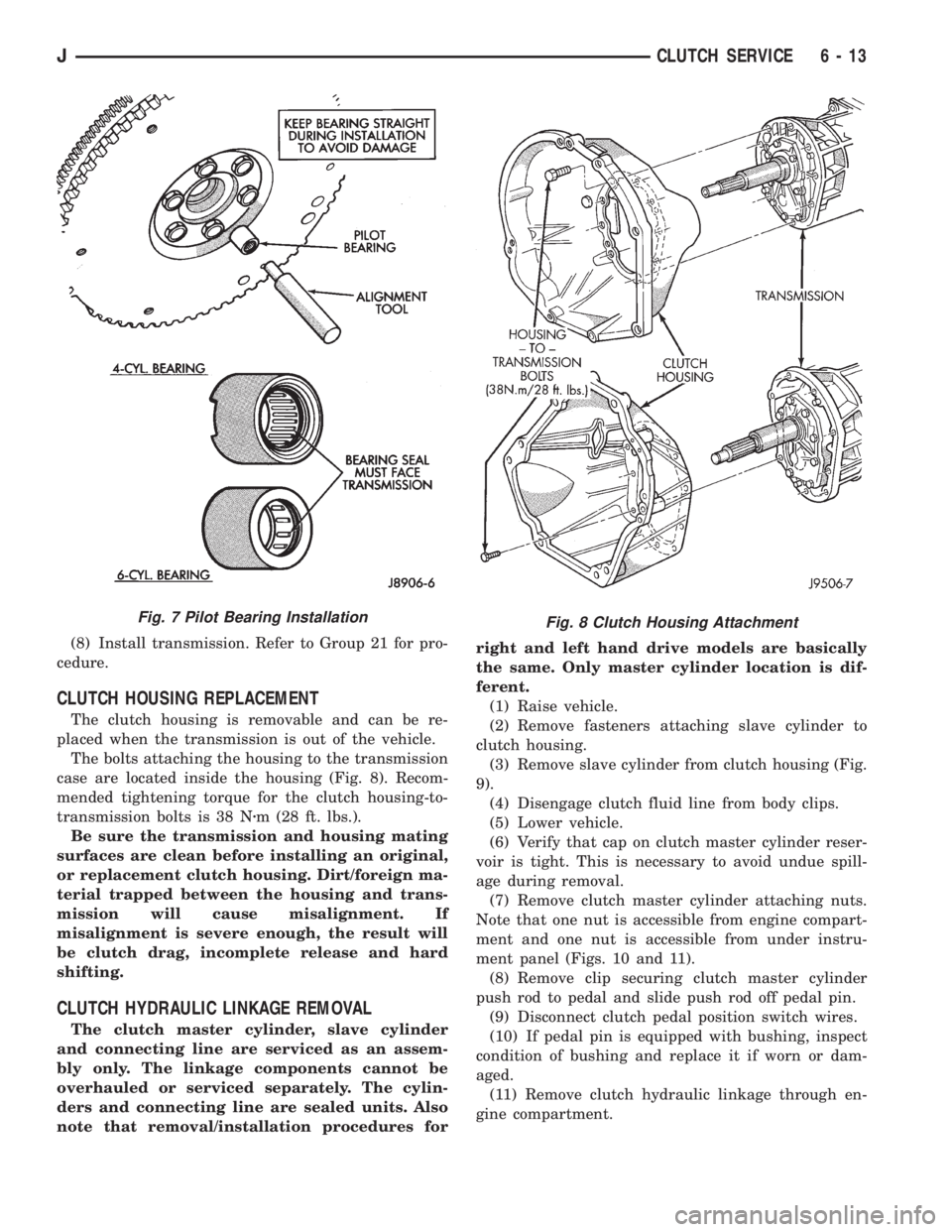
The bolts attaching the housing to the transmission
case are located inside the housing (Fig. 8). Recom-
mended tightening torque for the clutch housing-to-
transmission bolts is 38 Nzm (28 ft. lbs.).
Be sure the transmission and housing mating
surfaces are clean before installing an original,
or replacement clutch housing. Dirt/foreign ma-
terial trapped between the housing and trans-
mission will cause misalignment. If
misalignment is severe enough, the result will
be clutch drag, incomplete release and hard
shifting.
CLUTCH HYDRAULIC LINKAGE REMOVAL
The clutch master cylinder, slave cylinder
and connecting line are serviced as an assem-
bly only. The linkage components cannot be
overhauled or serviced separately. The cylin-
ders and connecting line are sealed units. Also
note that removal/installation procedures forright and left hand drive models are basically
the same. Only master cylinder location is dif-
ferent.
(1) Raise vehicle.
(2) Remove fasteners attaching slave cylinder to
clutch housing.
(3) Remove slave cylinder from clutch housing (Fig.
9).
(4) Disengage clutch fluid line from body clips.
(5) Lower vehicle.
(6) Verify that cap on clutch master cylinder reser-
voir is tight. This is necessary to avoid undue spill-
age during removal.
(7) Remove clutch master cylinder attaching nuts.
Note that one nut is accessible from engine compart-
ment and one nut is accessible from under instru-
ment panel (Figs. 10 and 11).
(8) Remove clip securing clutch master cylinder
push rod to pedal and slide push rod off pedal pin.
(9) Disconnect clutch pedal position switch wires.
(10) If pedal pin is equipped with bushing, inspect
condition of bushing and replace it if worn or dam-
aged.
(11) Remove clutch hydraulic linkage through en-
gine compartment.
Fig. 8 Clutch Housing AttachmentFig. 7 Pilot Bearing Installation
JCLUTCH SERVICE 6 - 13
Page 410 of 2158
(3) Remove screws holding speaker grille and
speaker to bar.
(4) Disconnect wires from speaker and remove
speaker.
(5) Reverse removal procedures to install.
SOUND BAR REMOVE/INSTALL - YJ
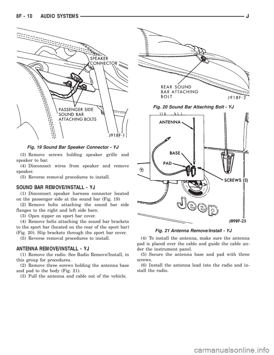
(1) Disconnect speaker harness connector located
on the passenger side at the sound bar (Fig. 19)
(2) Remove bolts attaching the sound bar side
flanges to the right and left side bars.
(3) Open zipper on sport bar cover.
(4) Remove bolts attaching the sound bar brackets
to the sport bar (located on the rear of the sport bar)
(Fig. 20). Slip brackets through the sport bar cover.
(5) Reverse removal procedures to install.
ANTENNA REMOVE/INSTALL - YJ
(1) Remove the radio. See Radio Remove/Install, in
this group for procedures.
(2) Remove three screws holding the antenna base
and pad to the body (Fig. 21).
(3) Pull the antenna and cable out of the vehicle.(4) To install the antenna, make sure the antenna
pad is placed over the cable and guide the cable un-
der the instrument panel.
(5) Secure the antenna base and pad with three
screws.
(6) Install the antenna lead into the radio and in-
stall the radio.
Fig. 19 Sound Bar Speaker Connector - YJ
Fig. 20 Sound Bar Attaching Bolt - YJ
Fig. 21 Antenna Remove/Install - YJ
8F - 10 AUDIO SYSTEMSJ
Page 472 of 2158
BACK-UP/REAR TURN SIGNAL/TAIL LAMP BULB
REPLACEMENTÐXJ
REMOVAL
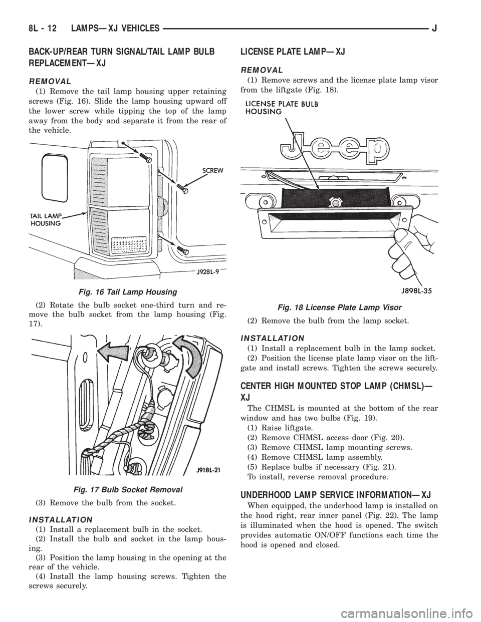
(1) Remove the tail lamp housing upper retaining
screws (Fig. 16). Slide the lamp housing upward off
the lower screw while tipping the top of the lamp
away from the body and separate it from the rear of
the vehicle.
(2) Rotate the bulb socket one-third turn and re-
move the bulb socket from the lamp housing (Fig.
17).
(3) Remove the bulb from the socket.
INSTALLATION
(1) Install a replacement bulb in the socket.
(2) Install the bulb and socket in the lamp hous-
ing.
(3) Position the lamp housing in the opening at the
rear of the vehicle.
(4) Install the lamp housing screws. Tighten the
screws securely.
LICENSE PLATE LAMPÐXJ
REMOVAL
(1) Remove screws and the license plate lamp visor
from the liftgate (Fig. 18).
(2) Remove the bulb from the lamp socket.
INSTALLATION
(1) Install a replacement bulb in the lamp socket.
(2) Position the license plate lamp visor on the lift-
gate and install screws. Tighten the screws securely.
CENTER HIGH MOUNTED STOP LAMP (CHMSL)Ð
XJ
The CHMSL is mounted at the bottom of the rear
window and has two bulbs (Fig. 19).
(1) Raise liftgate.
(2) Remove CHMSL access door (Fig. 20).
(3) Remove CHMSL lamp mounting screws.
(4) Remove CHMSL lamp assembly.
(5) Replace bulbs if necessary (Fig. 21).
To install, reverse removal procedure.
UNDERHOOD LAMP SERVICE INFORMATIONÐXJ
When equipped, the underhood lamp is installed on
the hood right, rear inner panel (Fig. 22). The lamp
is illuminated when the hood is opened. The switch
provides automatic ON/OFF functions each time the
hood is opened and closed.
Fig. 16 Tail Lamp Housing
Fig. 17 Bulb Socket Removal
Fig. 18 License Plate Lamp Visor
8L - 12 LAMPSÐXJ VEHICLESJ
Page 474 of 2158
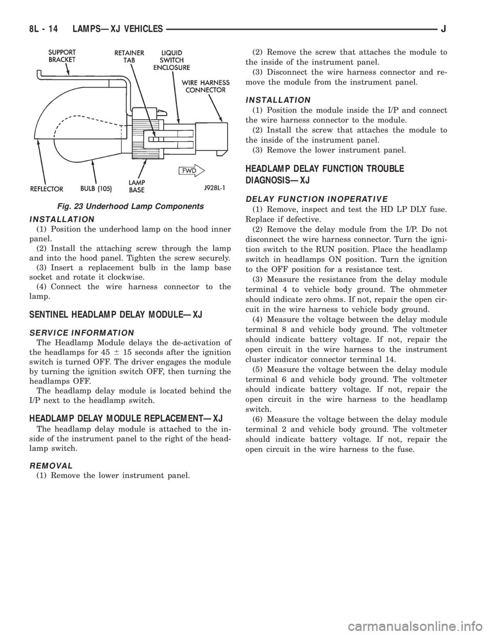
INSTALLATION
(1) Position the underhood lamp on the hood inner
panel.
(2) Install the attaching screw through the lamp
and into the hood panel. Tighten the screw securely.
(3) Insert a replacement bulb in the lamp base
socket and rotate it clockwise.
(4) Connect the wire harness connector to the
lamp.
SENTINEL HEADLAMP DELAY MODULEÐXJ
SERVICE INFORMATION
The Headlamp Module delays the de-activation of
the headlamps for 45615 seconds after the ignition
switch is turned OFF. The driver engages the module
by turning the ignition switch OFF, then turning the
headlamps OFF.
The headlamp delay module is located behind the
I/P next to the headlamp switch.
HEADLAMP DELAY MODULE REPLACEMENTÐXJ
The headlamp delay module is attached to the in-
side of the instrument panel to the right of the head-
lamp switch.
REMOVAL
(1) Remove the lower instrument panel.(2) Remove the screw that attaches the module to
the inside of the instrument panel.
(3) Disconnect the wire harness connector and re-
move the module from the instrument panel.
INSTALLATION
(1) Position the module inside the I/P and connect
the wire harness connector to the module.
(2) Install the screw that attaches the module to
the inside of the instrument panel.
(3) Remove the lower instrument panel.
HEADLAMP DELAY FUNCTION TROUBLE
DIAGNOSISÐXJ
DELAY FUNCTION INOPERATIVE
(1) Remove, inspect and test the HD LP DLY fuse.
Replace if defective.
(2) Remove the delay module from the I/P. Do not
disconnect the wire harness connector. Turn the igni-
tion switch to the RUN position. Place the headlamp
switch in headlamps ON position. Turn the ignition
to the OFF position for a resistance test.
(3) Measure the resistance from the delay module
terminal 4 to vehicle body ground. The ohmmeter
should indicate zero ohms. If not, repair the open cir-
cuit in the wire harness to vehicle body ground.
(4) Measure the voltage between the delay module
terminal 8 and vehicle body ground. The voltmeter
should indicate battery voltage. If not, repair the
open circuit in the wire harness to the instrument
cluster indicator connector terminal 14.
(5) Measure the voltage between the delay module
terminal 6 and vehicle body ground. The voltmeter
should indicate battery voltage. If not, repair the
open circuit in the wire harness to the headlamp
switch.
(6) Measure the voltage between the delay module
terminal 2 and vehicle body ground. The voltmeter
should indicate battery voltage. If not, repair the
open circuit in the wire harness to the fuse.Fig. 23 Underhood Lamp Components
8L - 14 LAMPSÐXJ VEHICLESJ
Page 491 of 2158
INTERIOR LAMPS
INDEX
page page
Dome/Courtesy Lamp Service InformationÐYJ . . . 31
Dome/Courtesy Lamp Trouble DiagnosisÐYJ.... 31Hardtop Dome/Cargo Lamp Bulb ReplacementÐYJ
Vehicles............................... 31
DOME/COURTESY LAMP SERVICE
INFORMATIONÐYJ
The dome/cargo and underpanel courtesy lamps are
controlled via ON/OFF switches. The ON/OFF
switches are in the lamp ground circuits. Voltage via
the dome/courtesy lamp fuse is applied directly to the
lamp bulbs. When either door is opened, the door pil-
lar switch contacts close and provide a direct path to
vehicle body ground.
The dome/cargo and underpanel courtesy lamps
can also be turned on via the interior lamp illumina-
tion rheostat.
DOME/COURTESY LAMP TROUBLE DIAGNOSISÐ
YJ
ALL LAMPS INOPERATIVE FROM INTERIOR
LAMP ILLUMINATION RHEOSTAT
(1) Rotate the interior lamp illumination rheostat
in an upward direction. The lamps should light. If
not OK, remove, inspect and test the dome lamp
fuse. Replace if bad.
(2) If the fuse is OK, repair the open circuit in the
wire harness to vehicle body ground.
(3) If lamp still does not light, replace the switch.
ONE LAMP INOPERATIVE
(1) Measure the resistance across the bulb holder
terminals. The ohmmeter should indicate zero ohms.
If not, replace the bulb.
(2) Measure the voltage between the voltage side
of the bulb holder and vehicle body ground. The volt-
meter should indicate battery voltage. If not, repair
the open circuit in the wire harness to the splice.
LAMPS INOPERATIVE WITH ONE OR MORE
DOORS OPENED
(1) Remove the inoperative switch from the door
pillar and connect the switch wire directly to ground.
The lamp should light.(2) If not, check for an open circuit in black
(ground) wire. Repair as necessary. If lamps still do
not light, replace the switch.
HARDTOP DOME/CARGO LAMP BULB
REPLACEMENTÐYJ VEHICLES
REMOVAL
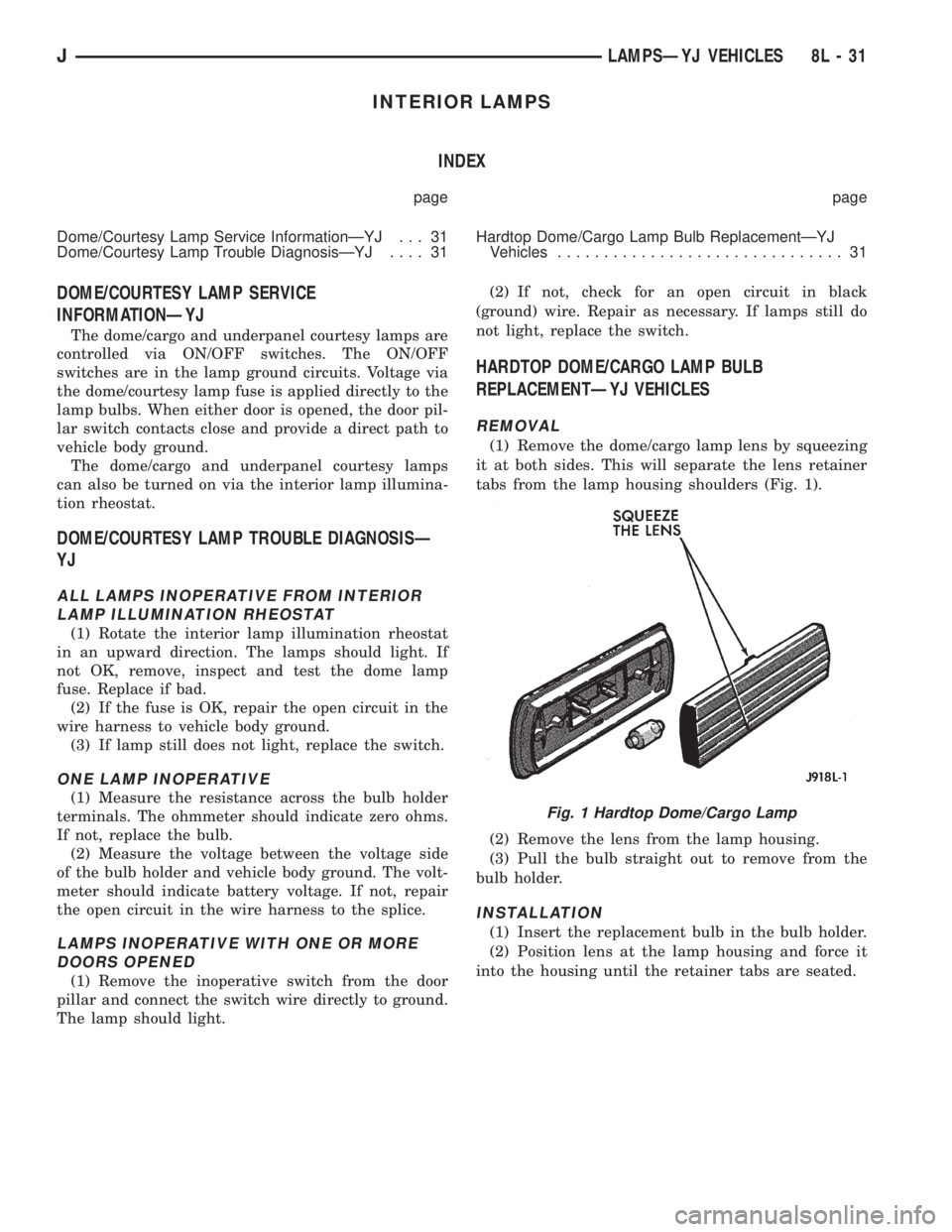
(1) Remove the dome/cargo lamp lens by squeezing
it at both sides. This will separate the lens retainer
tabs from the lamp housing shoulders (Fig. 1).
(2) Remove the lens from the lamp housing.
(3) Pull the bulb straight out to remove from the
bulb holder.
INSTALLATION
(1) Insert the replacement bulb in the bulb holder.
(2) Position lens at the lamp housing and force it
into the housing until the retainer tabs are seated.
Fig. 1 Hardtop Dome/Cargo Lamp
JLAMPSÐYJ VEHICLES 8L - 31