1995 JEEP YJ body panel removal
[x] Cancel search: body panel removalPage 2044 of 2158
(4) Apply weatherstrip adhesive to the hard top
weatherstrip seal (Fig. 4).
(5) Carefully position the weatherstrip seal on the
rear panels and the hard top.
(6) Press the seal onto the hard top flange and en-
sure that it is correctly seated on the flange.
(7) Install the seal retaining screws in the rear
panels and tighten them securely.
HARD TOPÐYJ
The hard top is constructed of compressed molded
fiberglass and painted to a special spatter paint. The
hard top can be removed for service access or for
other purposes.
REMOVAL
CAUTION: When removing the hard top, avoid dam-
aging the foam sealant between the hard top and
body panels.
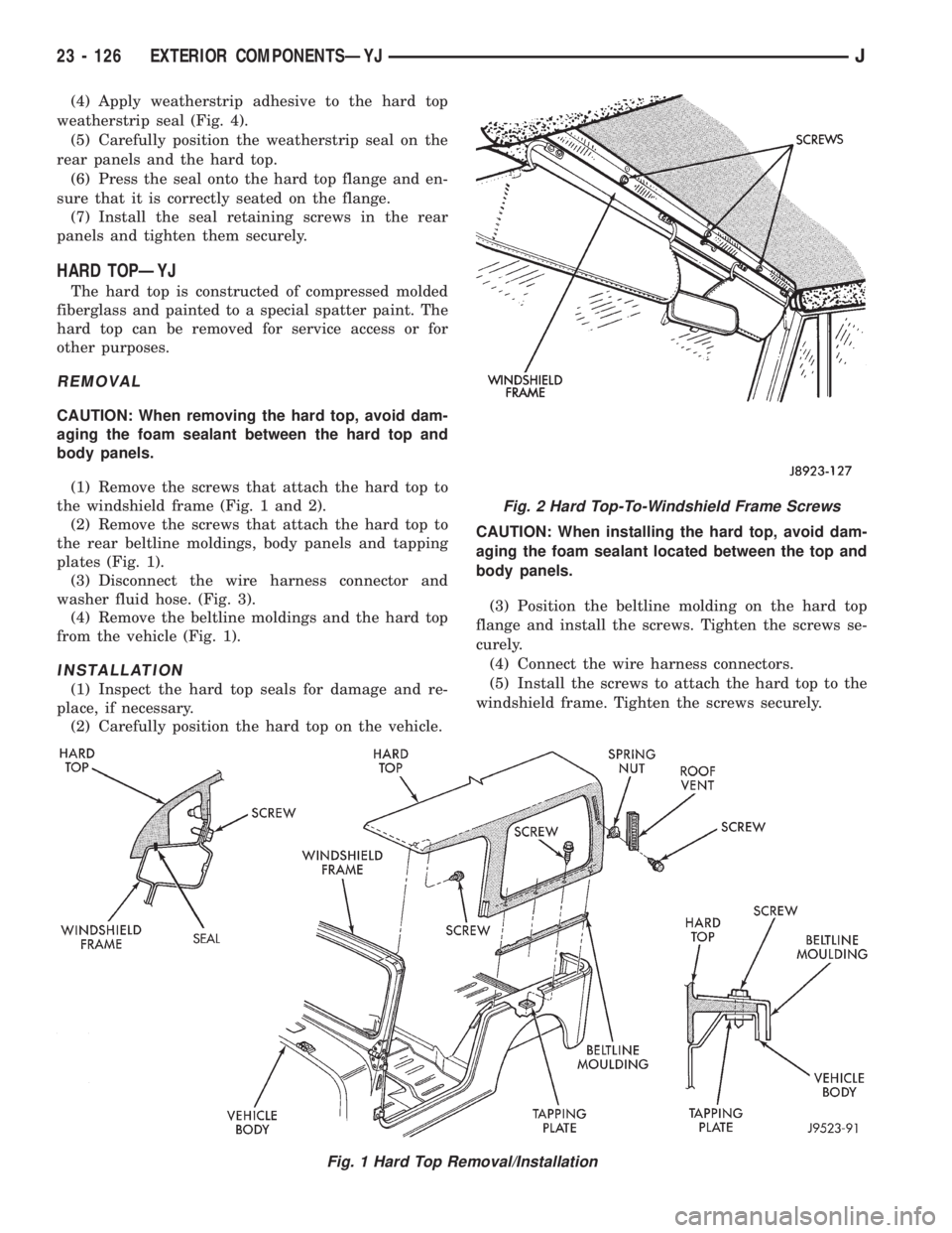
(1) Remove the screws that attach the hard top to
the windshield frame (Fig. 1 and 2).
(2) Remove the screws that attach the hard top to
the rear beltline moldings, body panels and tapping
plates (Fig. 1).
(3) Disconnect the wire harness connector and
washer fluid hose. (Fig. 3).
(4) Remove the beltline moldings and the hard top
from the vehicle (Fig. 1).
INSTALLATION
(1) Inspect the hard top seals for damage and re-
place, if necessary.
(2) Carefully position the hard top on the vehicle.CAUTION: When installing the hard top, avoid dam-
aging the foam sealant located between the top and
body panels.
(3) Position the beltline molding on the hard top
flange and install the screws. Tighten the screws se-
curely.
(4) Connect the wire harness connectors.
(5) Install the screws to attach the hard top to the
windshield frame. Tighten the screws securely.
Fig. 1 Hard Top Removal/Installation
Fig. 2 Hard Top-To-Windshield Frame Screws
23 - 126 EXTERIOR COMPONENTSÐYJJ
Page 2052 of 2158
DOORS
INDEX
page page
Beltline SealÐYJ........................ 142
Door Frame Glass Channel ReplacementÐYJ . . . 142
Door Weatherstrip Seal ReplacementÐYJ...... 142
Full-Metal Door Assist HandleÐYJ........... 136
Full-Metal Door HingesÐYJ................ 140
Full-Metal Door Key Lock CylinderÐYJ........ 139
Full-Metal Door Latch External Release
HandleÐYJ........................... 140
Full-Metal Door Latch Inside Release and Lock
HandleÐYJ........................... 137
Full-Metal Door LatchÐYJ.................. 140Full-Metal Door ServiceÐYJ................ 142
Full-Metal Door Trim PanelÐYJ.............. 137
Full-Metal Door Vent Window GlassÐYJ....... 137
Full-Metal Door WaterdamÐYJ.............. 137
Full-Metal Door Weatherstrip SealsÐYJ........ 141
Full-Metal Door Window Glass Regulator
HandleÐYJ........................... 136
Full-Metal Door Window Glass RegulatorÐYJ . . . 138
Full-Metal Door Window GlassÐYJ........... 139
Half-Metal Door Latch StrikerÐYJ............ 135
Half-Metal Soft Top DoorÐYJ............... 134
HALF-METAL SOFT TOP DOORÐYJ
REMOVAL/DISASSEMBLY
(1) Open the door.
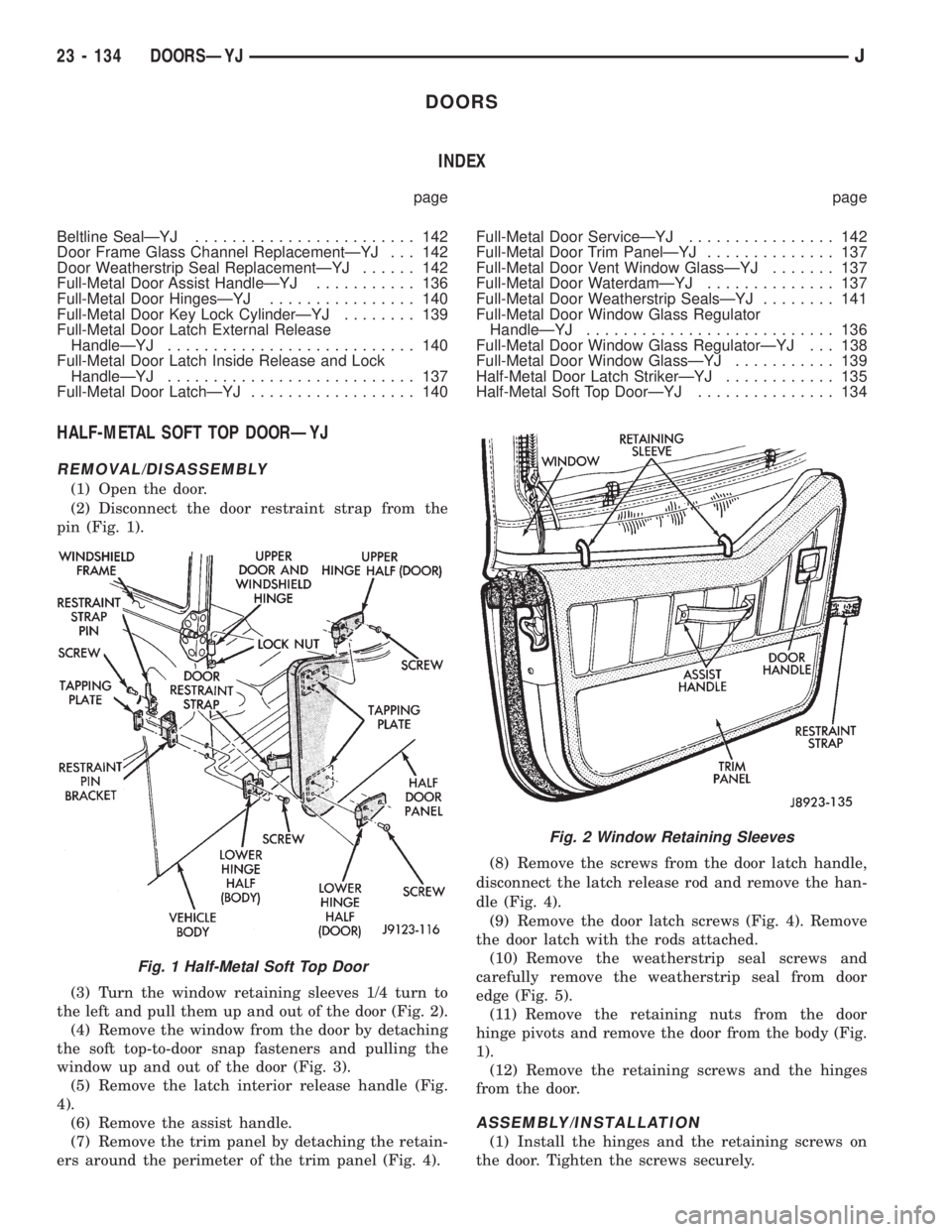
(2) Disconnect the door restraint strap from the
pin (Fig. 1).
(3) Turn the window retaining sleeves 1/4 turn to
the left and pull them up and out of the door (Fig. 2).
(4) Remove the window from the door by detaching
the soft top-to-door snap fasteners and pulling the
window up and out of the door (Fig. 3).
(5) Remove the latch interior release handle (Fig.
4).
(6) Remove the assist handle.
(7) Remove the trim panel by detaching the retain-
ers around the perimeter of the trim panel (Fig. 4).(8) Remove the screws from the door latch handle,
disconnect the latch release rod and remove the han-
dle (Fig. 4).
(9) Remove the door latch screws (Fig. 4). Remove
the door latch with the rods attached.
(10) Remove the weatherstrip seal screws and
carefully remove the weatherstrip seal from door
edge (Fig. 5).
(11) Remove the retaining nuts from the door
hinge pivots and remove the door from the body (Fig.
1).
(12) Remove the retaining screws and the hinges
from the door.
ASSEMBLY/INSTALLATION
(1) Install the hinges and the retaining screws on
the door. Tighten the screws securely.
Fig. 1 Half-Metal Soft Top Door
Fig. 2 Window Retaining Sleeves
23 - 134 DOORSÐYJJ
Page 2058 of 2158
FULL-METAL DOOR LATCH EXTERNAL RELEASE
HANDLEÐYJ
REMOVAL
(1) Remove the door trim panel and the waterdam
from the door inner panel (Fig. 8 and 10).
(2) Remove the door latch cover attaching screws
(Fig. 11).
(3) Remove the hitch pin and the latch release rod
from the door external handle (Fig. 13).
(4) Close the window completely and tap the han-
dle keepers upward (Fig. 13).
(5) Disconnect the window glass from the regulator
arm guide (Fig. 12).
(6) Remove the division channel upper and lower
attaching screws.
(7) Separate the division channel from the front
window glass weatherstrip seal.
(8) Pull the division channel upward and remove
the window glass from the door.
(9) Remove the keepers from the door handle with
needlenose pliers and remove the handle and gasket
from the door (Fig. 13 and 14).
INSTALLATION
(1) Install the gasket and the door external handle
and slide the keepers into the door handle from the
top (Fig. 13 and 14).
(2) Tap the retainers downward lightly to tighten
the handle.
(3) Install the latch release rod and the hitch pin
and attach the rod to the latch (Fig. 13).(4) Position the window glass in the door and the
channels.
(5) Install the division channel and the attaching
screws.
(6) Attach the window glass to the regulator arm
guide (Fig. 12).
(7) Install the door latch cover (Fig. 11).
(8) Install the door waterdam and the trim panel
(Fig. 8 and 10).
FULL-METAL DOOR LATCHÐYJ
REMOVAL
(1) Remove the trim panel and the waterdam from
the door inner panel (Fig. 8 and 10).
(2) Remove the door latch cover (Fig. 11).
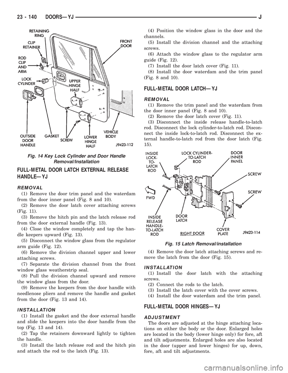
(3) Disconnect the inside release handle-to-latch
rod. Disconnect the lock cylinder-to-latch rod. Discon-
nect the inside lock-to-latch rod. Disconnect the ex-
ternal handle-to-latch rod from the door latch (Fig.
15).
(4) Remove the door latch attaching screws and re-
move the latch from the door (Fig. 15).
INSTALLATION
(1) Install the door latch with the attaching
screws.
(2) Connect the rods to the latch.
(3) Install the latch cover with the cover screws.
(4) Install the door waterdam and the trim panel.
FULL-METAL DOOR HINGESÐYJ
ADJUSTMENT
The doors are adjusted at the hinge attaching loca-
tions on either the body or the door. Enlarged holes
are located in the body (lower hinge only) for fore, aft
and tilt adjustments. Enlarged holes are also located
in the door (upper and lower hinges) for up, down,
fore, aft and tilt adjustments.
Fig. 14 Key Lock Cylinder and Door Handle
Removal/Installation
Fig. 15 Latch Removal/installation
23 - 140 DOORSÐYJJ
Page 2059 of 2158
Prior to door adjustment or alignment, the door
latch must be removed to allow the door to close
freely and be properly aligned.
The door latch striker should be adjusted in or out
to allow the door latch to be fully engaged. The door
should be flush with the adjacent body panels.
REPLACEMENT
(1) Mark the outline of the existing hinge on the
body and the door with a wax pencil for installation
alignment reference.
When removing the door or hinge DO NOT
discard the plastic shims or the hinge pin.
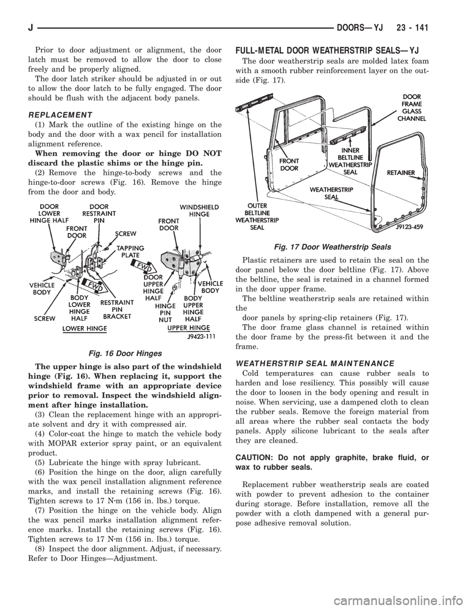
(2) Remove the hinge-to-body screws and the
hinge-to-door screws (Fig. 16). Remove the hinge
from the door and body.
The upper hinge is also part of the windshield
hinge (Fig. 16). When replacing it, support the
windshield frame with an appropriate device
prior to removal. Inspect the windshield align-
ment after hinge installation.
(3) Clean the replacement hinge with an appropri-
ate solvent and dry it with compressed air.
(4) Color-coat the hinge to match the vehicle body
with MOPAR exterior spray paint, or an equivalent
product.
(5) Lubricate the hinge with spray lubricant.
(6) Position the hinge on the door, align carefully
with the wax pencil installation alignment reference
marks, and install the retaining screws (Fig. 16).
Tighten screws to 17 Nzm (156 in. lbs.) torque.
(7) Position the hinge on the vehicle body. Align
the wax pencil marks installation alignment refer-
ence marks. Install the retaining screws (Fig. 16).
Tighten screws to 17 Nzm (156 in. lbs.) torque.
(8) Inspect the door alignment. Adjust, if necessary.
Refer to Door HingesÐAdjustment.
FULL-METAL DOOR WEATHERSTRIP SEALSÐYJ
The door weatherstrip seals are molded latex foam
with a smooth rubber reinforcement layer on the out-
side (Fig. 17).
Plastic retainers are used to retain the seal on the
door panel below the door beltline (Fig. 17). Above
the beltline, the seal is retained in a channel formed
in the door upper frame.
The beltline weatherstrip seals are retained within
the
door panels by spring-clip retainers (Fig. 17).
The door frame glass channel is retained within
the door frame by the press-fit between it and the
frame.
WEATHERSTRIP SEAL MAINTENANCE
Cold temperatures can cause rubber seals to
harden and lose resiliency. This possibly will cause
the door to loosen in the body opening and result in
noise. When servicing, use a dampened cloth to clean
the rubber seals. Remove the foreign material from
all areas where the rubber seal contacts the body
panels. Apply silicone lubricant to the seals after
they are cleaned.
CAUTION: Do not apply graphite, brake fluid, or
wax to rubber seals.
Replacement rubber weatherstrip seals are coated
with powder to prevent adhesion to the container
during storage. Before installation, remove all the
powder with a cloth dampened with a general pur-
pose adhesive removal solution.
Fig. 16 Door Hinges
Fig. 17 Door Weatherstrip Seals
JDOORSÐYJ 23 - 141
Page 2060 of 2158
DOOR WEATHERSTRIP SEAL REPLACEMENTÐYJ
REMOVAL
(1) Carefully remove the weatherstrip seal from
the door with a weatherstrip seal removal tool. Pry
the seal outward to separate the plastic retainers
from the door panel holes.
(2) Remove the upper portion of the seal from the
door upper frame with your fingers or a wooden
wand.
(3) Remove the dust and residual adhesive from
the door panel and body panel.
INSTALLATION
(1) Apply adhesive to the front, rear and bottom
edges of the door from the beltline downward.
(2) Install the upper front corner of the seal on the
door first using your fingers or a wooden wand to po-
sition the seal in the channel. Place the inner shoul-
der of the seal in the channel-to-window frame above
the beltline.
(3) Force the retainers, starting at the rear edge of
the door, into the door panel holes.
(4) Ensure that the seal is completely seated
around the door.
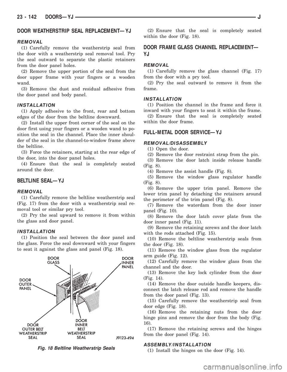
BELTLINE SEALÐYJ
REMOVAL
(1) Carefully remove the beltline weatherstrip seal
(Fig. 17) from the door with a weatherstrip seal re-
moval tool or similar pry tool.
(2) Pry the seal upward to remove it from within
the glass and door panel.
INSTALLATION
(1) Position the seal between the door panel and
the glass. Force the seal downward with your fingers
to seat it against the glass and panel (Fig. 18).(2) Ensure that the seal is completely seated
within the door (Fig. 18).
DOOR FRAME GLASS CHANNEL REPLACEMENTÐ
YJ
REMOVAL
(1) Carefully remove the glass channel (Fig. 17)
from the door with a pry tool.
(2) Pry the seal outward to remove it from the
frame.
INSTALLATION
(1) Position the channel in the frame and force it
inward with your fingers to seat it within the frame.
(2) Ensure that the seal is completely seated
within the door frame.
FULL-METAL DOOR SERVICEÐYJ
REMOVAL/DISASSEMBLY
(1) Open the door.
(2) Remove the door restraint strap from the pin.
(3) Remove the door latch inside release handle
(Fig. 8).
(4) Remove the assist handle (Fig. 8).
(5) Remove the window glass regulator handle
(Fig. 8).
(6) Remove the upper trim panel. Remove the
lower trim panel by detaching the retainers around
the perimeter of the trim panel (Fig. 8).
(7) Remove the waterdam from the door inner
panel (Fig. 10).
(8) Remove the door latch cover plate from the
door inner panel (Fig. 11).
(9) Remove the retaining screws and the door latch
with the rods attached (Fig. 15).
(10) Remove the beltline weatherstrip seals from
the door (Fig. 18).
(11) Remove the window glass from the regulator
arm guide (Fig. 12).
(12) Carefully remove the window glass from the
channel and the door.
(13) Remove the key lock cylinder from the door
(Fig. 14).
(14) Remove the door outside handle keepers, dis-
connect the latch release rod and remove the handle
from the door panel (Fig. 13).
(15) Carefully remove the weatherstrip seal from
door edge (Fig. 18).
(16) Remove the retaining nuts from the door
hinge pins and remove the door from the body (Fig.
16).
(17) Remove the retaining screws and the hinges
from the door panel (Fig. 14).
ASSEMBLY/INSTALLATION
(1) Install the hinges on the door (Fig. 14).Fig. 18 Beltline Weatherstrip Seals
23 - 142 DOORSÐYJJ
Page 2064 of 2158
WINDSHIELD FRAME WEATHERSTRIP SEALÐYJ
REMOVAL
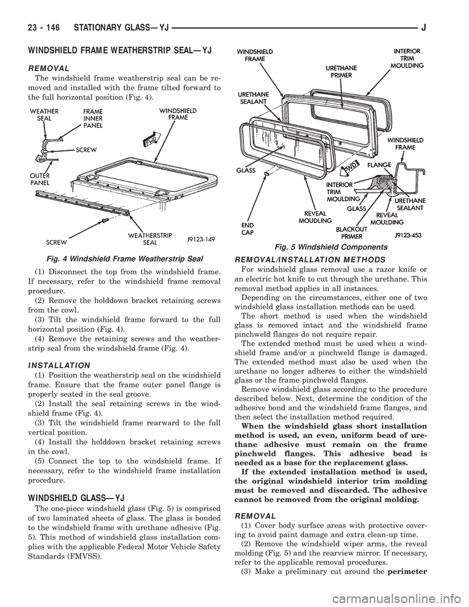
The windshield frame weatherstrip seal can be re-
moved and installed with the frame tilted forward to
the full horizontal position (Fig. 4).
(1) Disconnect the top from the windshield frame.
If necessary, refer to the windshield frame removal
procedure.
(2) Remove the holddown bracket retaining screws
from the cowl.
(3) Tilt the windshield frame forward to the full
horizontal position (Fig. 4).
(4) Remove the retaining screws and the weather-
strip seal from the windshield frame (Fig. 4).
INSTALLATION
(1) Position the weatherstrip seal on the windshield
frame. Ensure that the frame outer panel flange is
properly seated in the seal groove.
(2) Install the seal retaining screws in the wind-
shield frame (Fig. 4).
(3) Tilt the windshield frame rearward to the full
vertical position.
(4) Install the holddown bracket retaining screws
in the cowl.
(5) Connect the top to the windshield frame. If
necessary, refer to the windshield frame installation
procedure.
WINDSHIELD GLASSÐYJ
The one-piece windshield glass (Fig. 5) is comprised
of two laminated sheets of glass. The glass is bonded
to the windshield frame with urethane adhesive (Fig.
5). This method of windshield glass installation com-
plies with the applicable Federal Motor Vehicle Safety
Standards (FMVSS).
REMOVAL/INSTALLATION METHODS
For windshield glass removal use a razor knife or
an electric hot knife to cut through the urethane. This
removal method applies in all instances.
Depending on the circumstances, either one of two
windshield glass installation methods can be used.
The short method is used when the windshield
glass is removed intact and the windshield frame
pinchweld flanges do not require repair.
The extended method must be used when a wind-
shield frame and/or a pinchweld flange is damaged.
The extended method must also be used when the
urethane no longer adheres to either the windshield
glass or the frame pinchweld flanges.
Remove windshield glass according to the procedure
described below. Next, determine the condition of the
adhesive bond and the windshield frame flanges, and
then select the installation method required.
When the windshield glass short installation
method is used, an even, uniform bead of ure-
thane adhesive must remain on the frame
pinchweld flanges. This adhesive bead is
needed as a base for the replacement glass.
If the extended installation method is used,
the original windshield interior trim molding
must be removed and discarded. The adhesive
cannot be removed from the original molding.
REMOVAL
(1) Cover body surface areas with protective cover-
ing to avoid paint damage and extra clean-up time.
(2) Remove the windshield wiper arms, the reveal
molding (Fig. 5) and the rearview mirror. If necessary,
refer to the applicable removal procedures.
(3) Make a preliminary cut around theperimeter
Fig. 4 Windshield Frame Weatherstrip Seal
Fig. 5 Windshield Components
23 - 146 STATIONARY GLASSÐYJJ
Page 2106 of 2158
HEATER CORE
REVIEW WARNINGS AND CAUTIONS IN
THIS GROUP BEFORE PERFORMING THIS
OPERATION.
REMOVAL
(1) Drain the radiator.
(2) Disconnect heater hoses at heater core tubes.
(3) Remove heater/evaporator housing side cover.
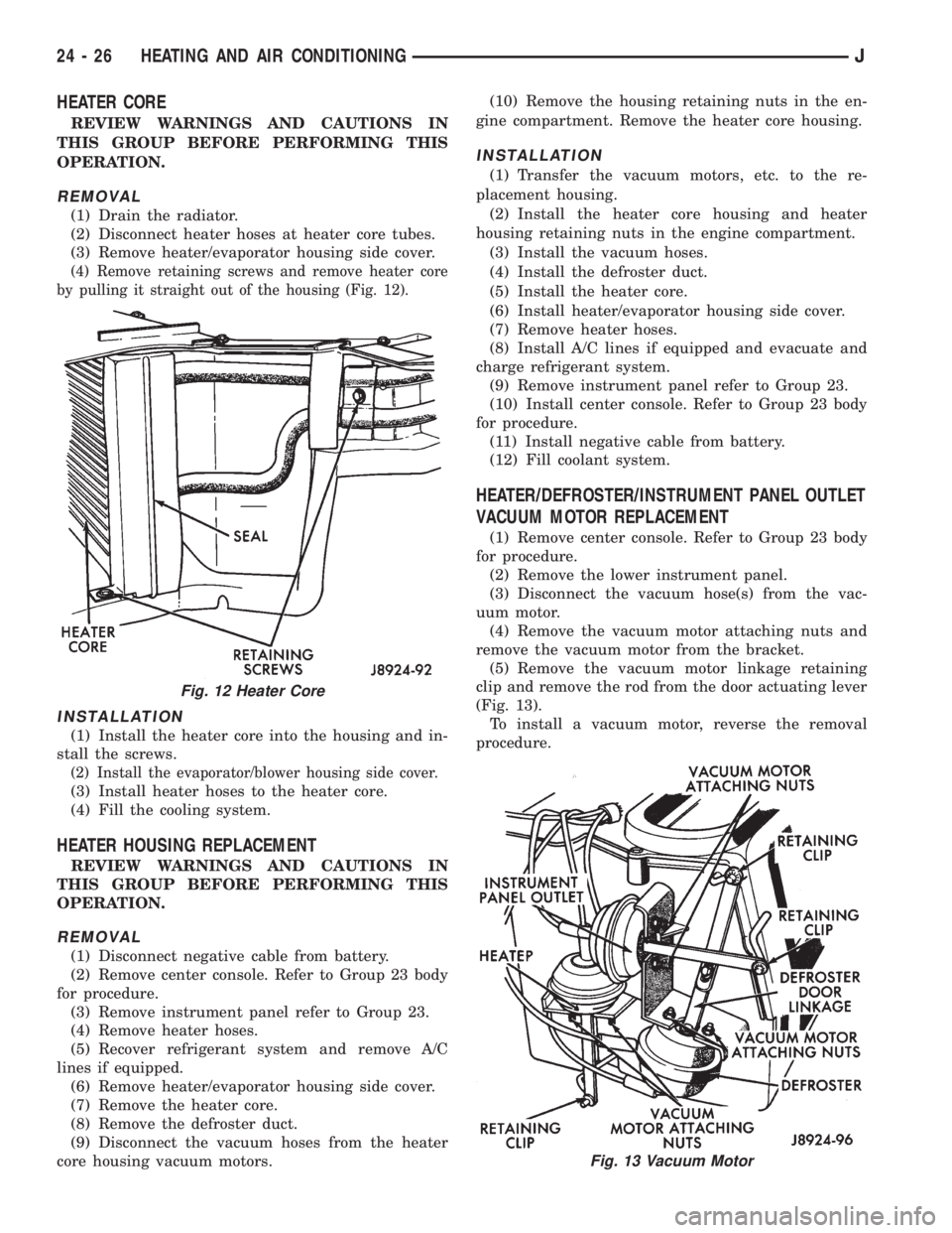
(4) Remove retaining screws and remove heater core
by pulling it straight out of the housing (Fig. 12).
INSTALLATION
(1) Install the heater core into the housing and in-
stall the screws.
(2) Install the evaporator/blower housing side cover.
(3) Install heater hoses to the heater core.
(4) Fill the cooling system.
HEATER HOUSING REPLACEMENT
REVIEW WARNINGS AND CAUTIONS IN
THIS GROUP BEFORE PERFORMING THIS
OPERATION.
REMOVAL
(1) Disconnect negative cable from battery.
(2) Remove center console. Refer to Group 23 body
for procedure.
(3) Remove instrument panel refer to Group 23.
(4) Remove heater hoses.
(5) Recover refrigerant system and remove A/C
lines if equipped.
(6) Remove heater/evaporator housing side cover.
(7) Remove the heater core.
(8) Remove the defroster duct.
(9) Disconnect the vacuum hoses from the heater
core housing vacuum motors.(10) Remove the housing retaining nuts in the en-
gine compartment. Remove the heater core housing.
INSTALLATION
(1) Transfer the vacuum motors, etc. to the re-
placement housing.
(2) Install the heater core housing and heater
housing retaining nuts in the engine compartment.
(3) Install the vacuum hoses.
(4) Install the defroster duct.
(5) Install the heater core.
(6) Install heater/evaporator housing side cover.
(7) Remove heater hoses.
(8) Install A/C lines if equipped and evacuate and
charge refrigerant system.
(9) Remove instrument panel refer to Group 23.
(10) Install center console. Refer to Group 23 body
for procedure.
(11) Install negative cable from battery.
(12) Fill coolant system.
HEATER/DEFROSTER/INSTRUMENT PANEL OUTLET
VACUUM MOTOR REPLACEMENT
(1) Remove center console. Refer to Group 23 body
for procedure.
(2) Remove the lower instrument panel.
(3) Disconnect the vacuum hose(s) from the vac-
uum motor.
(4) Remove the vacuum motor attaching nuts and
remove the vacuum motor from the bracket.
(5) Remove the vacuum motor linkage retaining
clip and remove the rod from the door actuating lever
(Fig. 13).
To install a vacuum motor, reverse the removal
procedure.
Fig. 12 Heater Core
Fig. 13 Vacuum Motor
24 - 26 HEATING AND AIR CONDITIONINGJ
Page 2109 of 2158
(1) Install the filter drier.
(2) Install and tighten the nut attaching the filter
drier to the side sill weld stud.
(3) Plug the harness to the low pressure switch.
(4) Remove the plugs the openings. Connect the
A/C hoses to the receiver dryer.
(5) Evacuate and charge the A/C system.
EVAPORATOR/BLOWER HOUSING
REVIEW WARNINGS AND CAUTIONS IN
THIS GROUP BEFORE PERFORMING THIS
OPERATION.
REMOVAL
(1) Disconnect negative cable from battery.
(2) Recover refrigerant from A/C system and dis-
connect A/C lines from the expansion valve.
(3) Disconnect the blower motor wires and the vent
tube.
(4) Remove center console. Refer to Group 23 body
for procedure.
(5) Remove the lower instrument panel.
(6) Disconnect the electrical connections at the
blower motor resistors and cycling clutch switch. Dis-
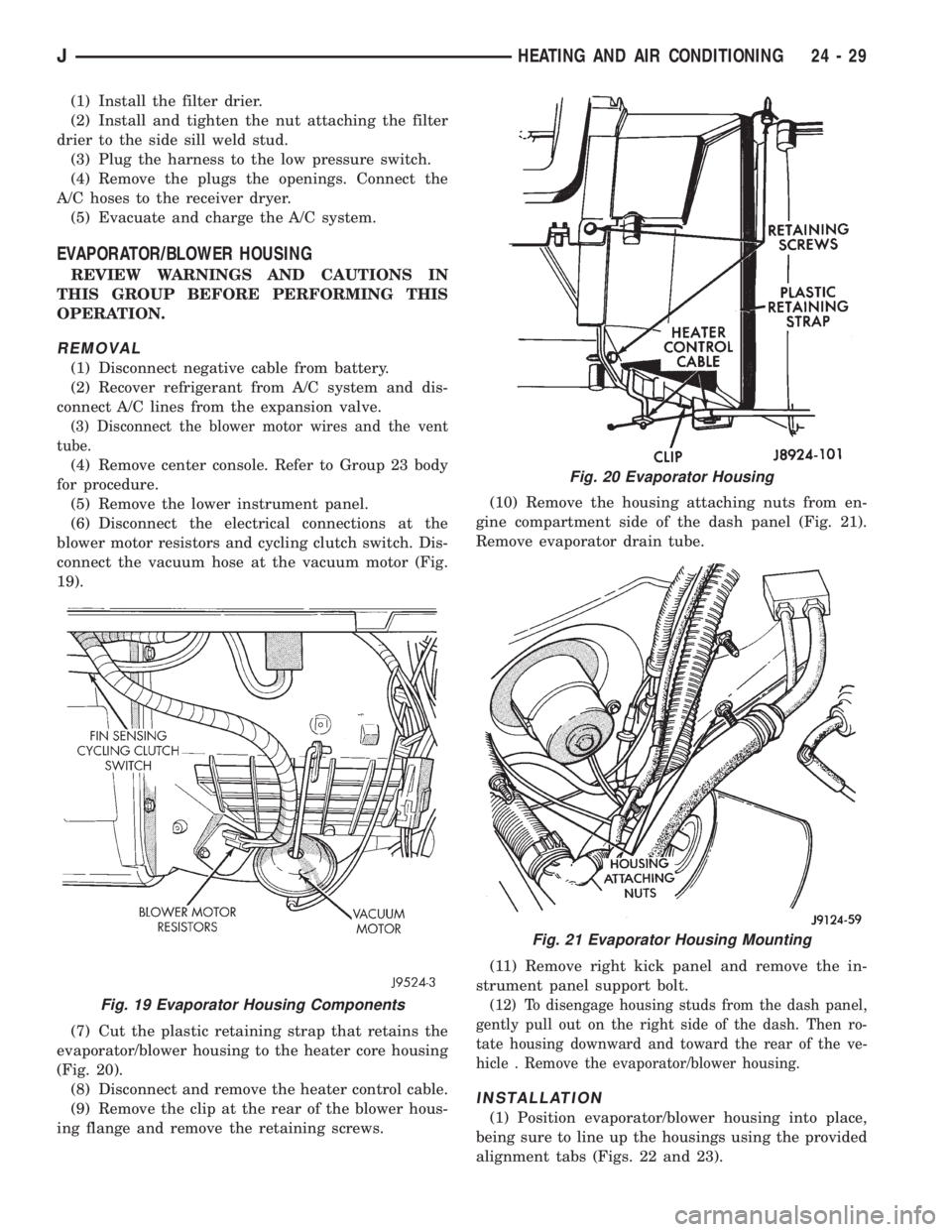
connect the vacuum hose at the vacuum motor (Fig.
19).
(7) Cut the plastic retaining strap that retains the
evaporator/blower housing to the heater core housing
(Fig. 20).
(8) Disconnect and remove the heater control cable.
(9) Remove the clip at the rear of the blower hous-
ing flange and remove the retaining screws.(10) Remove the housing attaching nuts from en-
gine compartment side of the dash panel (Fig. 21).
Remove evaporator drain tube.
(11) Remove right kick panel and remove the in-
strument panel support bolt.
(12) To disengage housing studs from the dash panel,
gently pull out on the right side of the dash. Then ro-
tate housing downward and toward the rear of the ve-
hicle . Remove the evaporator/blower housing.
INSTALLATION
(1) Position evaporator/blower housing into place,
being sure to line up the housings using the provided
alignment tabs (Figs. 22 and 23).
Fig. 19 Evaporator Housing Components
Fig. 20 Evaporator Housing
Fig. 21 Evaporator Housing Mounting
JHEATING AND AIR CONDITIONING 24 - 29