1995 JEEP YJ body panel removal
[x] Cancel search: body panel removalPage 1921 of 2158
EXTERIOR COMPONENTS
INDEX
page page
Air Exhaust GrilleÐXJ...................... 25
Battery TrayÐXJ.......................... 14
Body Side Molding/CladdingÐXJ.............. 20
Body Stripes/DecalsÐXJ.................... 21
Brush GuardÐXJ.......................... 3
Cowl Grille and ScreenÐXJ................. 12
Cowl Weatherstrip Seal/Crossmember Air
DeflectorÐXJ........................... 11
Dash Panel Insulator PanelÐXJ.............. 12
Drip Rail MoldingÐXJ...................... 25
Exterior NameplatesÐXJ................... 26
External MirrorsÐXJ....................... 27
Front FenderÐXJ......................... 14
Fuel Filler Door BumpersÐXJ................ 27Fuel Filler Nozzle/TubeÐXJ................. 26
Grille and Grille Opening Panel (GOP)ÐXJ....... 3
Hood AdjustmentÐXJ...................... 10
Hood Hinge ReplacementÐXJ............... 10
Hood Latch ReplacementÐXJ................ 11
Hood Latch Striker ReplacementÐXJ.......... 11
HoodÐXJ................................ 7
Latch Release Cable ReplacementÐXJ......... 11
Luggage RackÐXJ........................ 28
Quarter Window AppliqueÐXJ................ 25
Radiator Support CrossmemberÐXJ............ 6
Rear Wheelhouse Flares and LinersÐXJ........ 19
Safety Latch Striker ReplacementÐXJ.......... 11
BRUSH GUARDÐXJ
REMOVAL
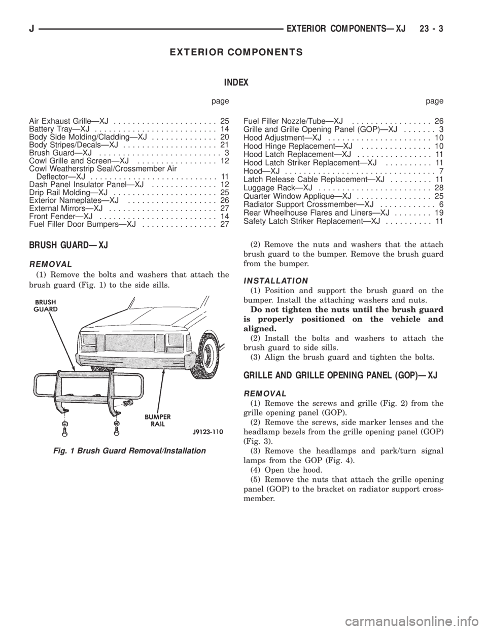
(1) Remove the bolts and washers that attach the
brush guard (Fig. 1) to the side sills.(2) Remove the nuts and washers that the attach
brush guard to the bumper. Remove the brush guard
from the bumper.INSTALLATION
(1) Position and support the brush guard on the
bumper. Install the attaching washers and nuts.
Do not tighten the nuts until the brush guard
is properly positioned on the vehicle and
aligned.
(2) Install the bolts and washers to attach the
brush guard to side sills.
(3) Align the brush guard and tighten the bolts.
GRILLE AND GRILLE OPENING PANEL (GOP)ÐXJ
REMOVAL
(1) Remove the screws and grille (Fig. 2) from the
grille opening panel (GOP).
(2) Remove the screws, side marker lenses and the
headlamp bezels from the grille opening panel (GOP)
(Fig. 3).
(3) Remove the headlamps and park/turn signal
lamps from the GOP (Fig. 4).
(4) Open the hood.
(5) Remove the nuts that attach the grille opening
panel (GOP) to the bracket on radiator support cross-
member.
Fig. 1 Brush Guard Removal/Installation
JEXTERIOR COMPONENTSÐXJ 23 - 3
Page 1936 of 2158
INSTALLATION
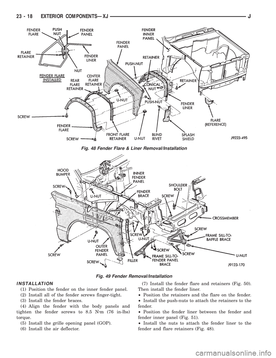
(1) Position the fender on the inner fender panel.
(2) Install all of the fender screws finger-tight.
(3) Install the fender braces.
(4) Align the fender with the body panels and
tighten the fender screws to 8.5 Nzm (76 in-lbs)
torque.
(5) Install the grille opening panel (GOP).
(6) Install the air deflector.(7) Install the fender flare and retainers (Fig. 50).
Then install the fender liner.
²Position the retainers and the flare on the fender.
²Install the push-nuts to attach the retainers to the
fender.
²Position the fender liner between the fender and
fender inner panel (Fig. 51).
²Install the nuts to attach the fender liner to the
fender and flare retainers (Fig. 48).
Fig. 48 Fender Flare & Liner Removal/Installation
Fig. 49 Fender Removal/Installation
23 - 18 EXTERIOR COMPONENTSÐXJJ
Page 1938 of 2158
(4) Install the nuts to attach the liner to the
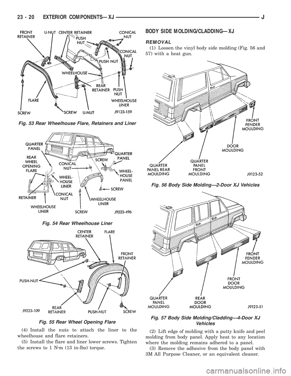
wheelhouse and flare retainers.
(5) Install the flare and liner lower screws. Tighten
the screws to 1 Nzm (13 in-lbs) torque.
BODY SIDE MOLDING/CLADDINGÐXJ
REMOVAL
(1) Loosen the vinyl body side molding (Fig. 56 and
57) with a heat gun.
(2) Lift edge of molding with a putty knife and peel
molding from body panel. Apply heat to any location
where the molding remains adhered to a panel.
(3) Remove the adhesive from the body panel with
3M All Purpose Cleaner, or an equivalent cleaner.
Fig. 53 Rear Wheelhouse Flare, Retainers and Liner
Fig. 54 Rear Wheelhouse Liner
Fig. 55 Rear Wheel Opening Flare
Fig. 56 Body Side MoldingÐ2-Door XJ Vehicles
Fig. 57 Body Side Molding/CladdingÐ4-Door XJ
Vehicles
23 - 20 EXTERIOR COMPONENTSÐXJJ
Page 1939 of 2158
(4) If the original molding will be installed, also re-
move all adhesive from it.
INSTALLATION
(1) Install 3M 06379 double-sided tape on the
molding.
(2) For vertical alignment, use masking tape or a
string as reference.
(3) Remove the backing from the tape, align the
molding and position it on the body panel.
(4) Press the molding onto the body panel with a
roller or hand pressure.
BODY STRIPES/DECALSÐXJ
SERVICE INFORMATION
XJ body stripes and decals are weather resistant
tape with a adhesive backing.
REPAIR
Small nicks, scratches and other surface marks in
a body stripe/decal can be touched-up with paint.
To eliminate blisters and air bubbles in a body
stripe/decal, pierce them with a needle or pin.
A heat gun can also be used to remove small wrin-
kles in a stripe/decal.
REQUIREMENTS
Body stripe/decal replacement requires that the
metal repair and paint refinish be completed first.
The work area temperature should be between
18ÉC (65ÉF) and 32ÉC (90ÉF).A tape stripe/decal
should not be replaced if the work area temper-
ature is less than 18ÉC (65ÉF).
The following equipment and material are neces-
sary for removal and installation:
²Commercial tape stripe/decal removal solution.
²Commercial adhesive removal solution.
²Liquid dish detergent (for the wetting solution).
²Mixture of wetting solution.
²Commercial wax and silicone removal solution.
²Isopropyl (rubbing) alcohol.
²Small squeegee (plastic or hard rubber).
²Water bucket and sponge.
²Clean wiping rags or paper towels.
²Heat gun (or infra-red heat bulb).
²Wax pencil.
²
Sharp knife, single edge razor blade or X-acto knife.
²Pair of scissors.
²Needle or pin.
The use of a wetting solution aids the installation of a
tape stripe/decal on a painted panel. Prepare the wet-
ting solution by mixing two or three teaspoons of dish
detergent with 1 gallon of water.Do not use soap.
Too much detergent will reduce the effective-
ness of the mixture.
REMOVAL
(1) Clean the repaired surface, adjacent panels and
door the openings as necessary.
(2) Start at one end of the tape stripe/decal and
apply heat with a heat gun. Slowly peel the stripe/
decal from the panel by pulling it back.Do not pull
the tape stripe/decal outward from panel.
WARNING: USE TAPE STRIPE/DECAL REMOVAL
SOLUTION IN A WELL-VENTILATED AREA ONLY.
(3) A tape stripe/decal removal solution can be used
for removal at areas where a heat gun is ineffective:
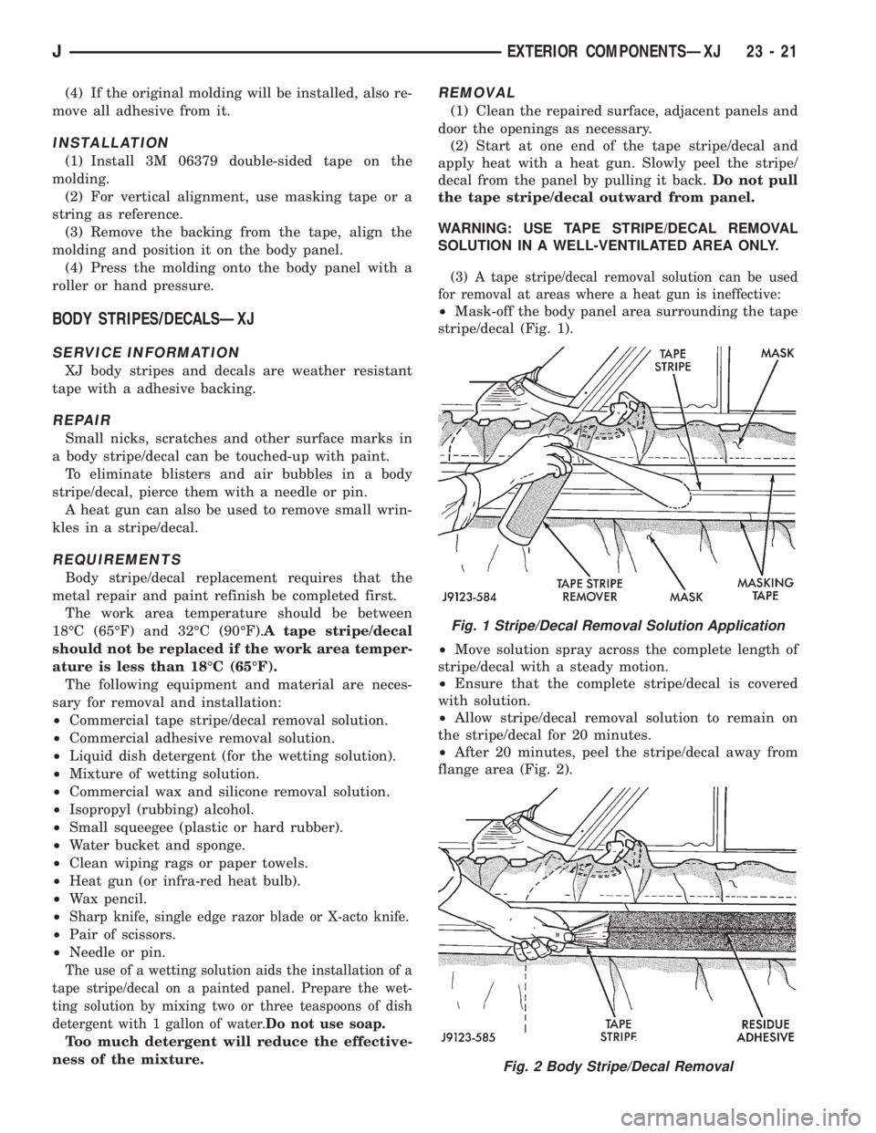
²Mask-off the body panel area surrounding the tape
stripe/decal (Fig. 1).
²Move solution spray across the complete length of
stripe/decal with a steady motion.
²Ensure that the complete stripe/decal is covered
with solution.
²Allow stripe/decal removal solution to remain on
the stripe/decal for 20 minutes.
²After 20 minutes, peel the stripe/decal away from
flange area (Fig. 2).
Fig. 1 Stripe/Decal Removal Solution Application
Fig. 2 Body Stripe/Decal Removal
JEXTERIOR COMPONENTSÐXJ 23 - 21
Page 1940 of 2158
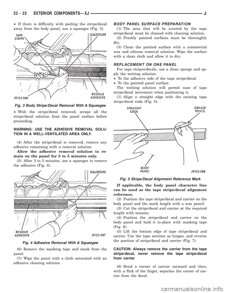
²If there is difficulty with peeling the stripe/decal
away from the body panel, use a squeegee (Fig. 3).
²With the stripe/decal removed, scrape all the
stripe/decal solution from the panel surface before
proceeding.
WARNING: USE THE ADHESIVE REMOVAL SOLU-
TION IN A WELL-VENTILATED AREA ONLY.
(4) After the stripe/decal is removed, remove any
adhesive remaining with a removal solution.
Allow the adhesive removal solution to re-
main on the panel for 3 to 5 minutes only.
(5) After 3 to 5 minutes, use a squeegee to remove
the adhesive (Fig. 4).
(6) Remove the masking tape and mask from the
panel.
(7) Wipe the panel with a cloth saturated with an
adhesive cleaning solution.BODY PANEL SURFACE PREPARATION
(1) The area that will be covered by the tape
stripe/decal must be cleaned with cleaning solution.
(2) Freshly painted surfaces must be thoroughly
dry.
(3) Clean the painted surface with a commercial
wax and silicone removal solution. Wipe the surface
with a clean cloth and allow it to dry.
REPLACEMENT ON ONE PANEL
For tape stripes/decals, use a clean sponge and ap-
ply the wetting solution:
²To the adhesive side of the tape stripe/decal.
²To the painted panel surface.
The wetting solution will permit ease of tape
stripe/decal movement when positioning it.
(1) Align a straight edge with the existing tape
stripe/decal ends (Fig. 5).
If applicable, the body panel character line
can be used as the tape stripe/decal alignment
reference.
(2) Position the tape stripe/decal and carrier on the
body panel and the mark length with a wax pencil.
(3) Cut the stripe/decal and carrier at the required
length with scissors.
(4) Position the stripe/decal and carrier on the
body panel and hold it in-place with masking tape
(Fig. 6).
(5) Lift the bottom edge of tape stripe/decal and
carrier. Use the tape sections as hinges, and reverse
the position of stripe/decal and carrier (Fig. 7).
CAUTION: Always remove the carrier from the tape
stripe/decal, never remove the tape stripe/decal
from carrier
(6) Bend a corner of carrier outward and then,
with a flick of the finger, separate the corner of car-
rier from the decal.
Fig. 3 Body Stripe/Decal Removal With A Squeegee
Fig. 4 Adhesive Removal With A Squeegee
Fig. 5 Stripe/Decal Alignment Reference Mark
23 - 22 EXTERIOR COMPONENTSÐXJJ
Page 1962 of 2158
INSTALLATION
(1) Position the glass in the door and install the
regulator-to-glass retainer, bushing and screw.
(2) Tighten the screw to 4 Nzm (36 in-lbs) torque.
(3) Install the channel bottom screw. Tighten the
screw to 9 Nzm (7 ft-lbs) torque.
(4) Install the channel hardware, beltline molding
and weatherstrip seals.(Fig. 27 and 28).
(5) Attach the door waterdam to the door inner
panel with adhesive/sealant.
(6) Install the door trim panel.
REAR DOOR WINDOW GLASS REGULATORÐXJ
REMOVAL
(1) Remove the door trim panel and waterdam.
(2) Remove the window glass attaching screw,
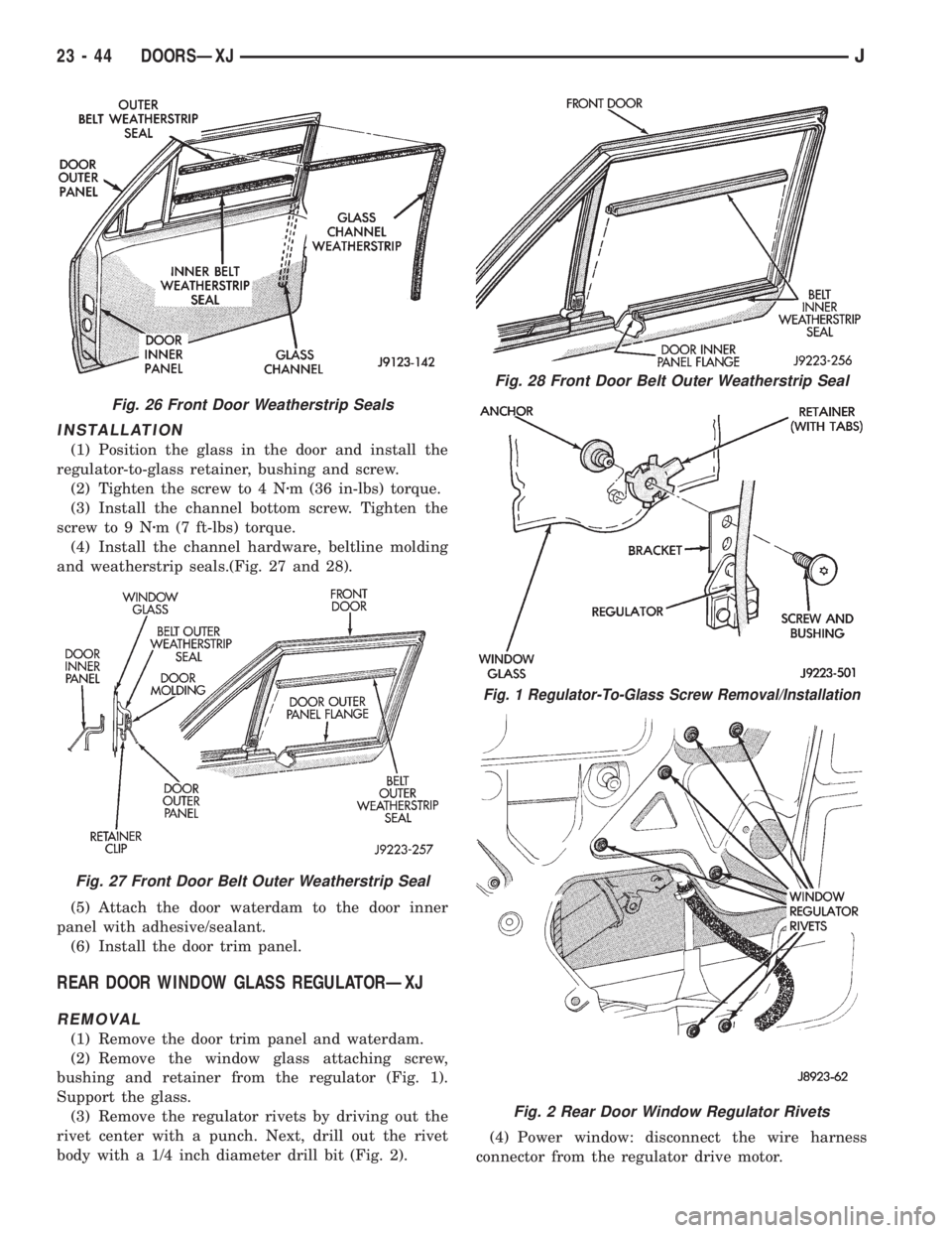
bushing and retainer from the regulator (Fig. 1).
Support the glass.
(3) Remove the regulator rivets by driving out the
rivet center with a punch. Next, drill out the rivet
body with a 1/4 inch diameter drill bit (Fig. 2).(4) Power window: disconnect the wire harness
connector from the regulator drive motor.
Fig. 26 Front Door Weatherstrip Seals
Fig. 27 Front Door Belt Outer Weatherstrip Seal
Fig. 28 Front Door Belt Outer Weatherstrip Seal
Fig. 1 Regulator-To-Glass Screw Removal/Installation
Fig. 2 Rear Door Window Regulator Rivets
23 - 44 DOORSÐXJJ
Page 1977 of 2158
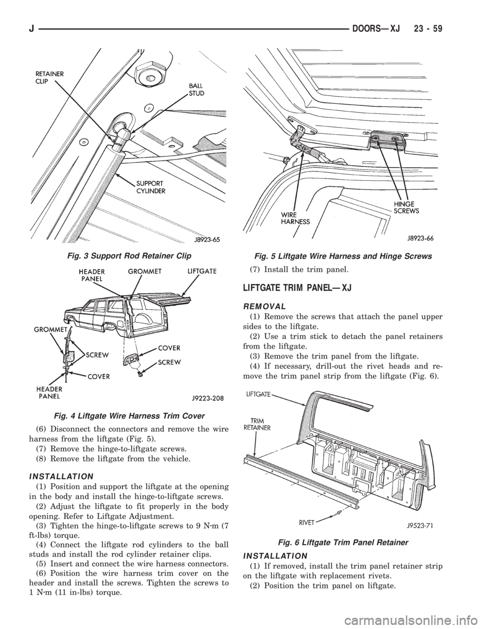
(6) Disconnect the connectors and remove the wire
harness from the liftgate (Fig. 5).
(7) Remove the hinge-to-liftgate screws.
(8) Remove the liftgate from the vehicle.
INSTALLATION
(1) Position and support the liftgate at the opening
in the body and install the hinge-to-liftgate screws.
(2) Adjust the liftgate to fit properly in the body
opening. Refer to Liftgate Adjustment.
(3) Tighten the hinge-to-liftgate screws to 9 Nzm(7
ft-lbs) torque.
(4) Connect the liftgate rod cylinders to the ball
studs and install the rod cylinder retainer clips.
(5) Insert and connect the wire harness connectors.
(6) Position the wire harness trim cover on the
header and install the screws. Tighten the screws to
1Nzm (11 in-lbs) torque.(7) Install the trim panel.
LIFTGATE TRIM PANELÐXJ
REMOVAL
(1) Remove the screws that attach the panel upper
sides to the liftgate.
(2) Use a trim stick to detach the panel retainers
from the liftgate.
(3) Remove the trim panel from the liftgate.
(4) If necessary, drill-out the rivet heads and re-
move the trim panel strip from the liftgate (Fig. 6).
INSTALLATION
(1) If removed, install the trim panel retainer strip
on the liftgate with replacement rivets.
(2) Position the trim panel on liftgate.
Fig. 3 Support Rod Retainer Clip
Fig. 4 Liftgate Wire Harness Trim Cover
Fig. 5 Liftgate Wire Harness and Hinge Screws
Fig. 6 Liftgate Trim Panel Retainer
JDOORSÐXJ 23 - 59
Page 2022 of 2158
EXTERIOR COMPONENTS
INDEX
page page
Battery TrayÐYJ......................... 110
Body Side Step MoldingÐYJ................ 115
Body Stripes/DecalsÐYJ................... 116
Cowl Grille and ScreenÐYJ................ 109
Cowl Weatherstrip SealÐYJ................ 109
Exterior Nameplates (Adhesive-Backed)ÐYJ.... 120
External Spare/Wheel Tire CarrierÐYJ........ 133
Fender FlareÐYJ........................ 114
Fender Inner Splash ShieldsÐYJ............. 116
Fender Splash ApronsÐYJ................. 115
FendersÐYJ............................ 110
Fuel Filler Protector/NozzleÐYJ............. 121
Half Metal Door Mirror (External)ÐYJ......... 121
Hard Top Liftgate GlassÐYJ................ 124
Hard Top RepairÐYJ..................... 127
Hard Top Roof VentÐYJ................... 127
Hard TopÐYJ........................... 126Hood AlignmentÐYJ...................... 107
Hood Insulator PanelÐYJ.................. 107
Hood Safety LatchÐYJ.................... 109
HoodÐYJ.............................. 107
Liftgate Glass Weatherstrip Seal ReplacementÐYJ. 125
Radiator Grille AppliqueÐYJ................ 104
Soft Top Service InformationÐYJ............. 127
Soft Top ServiceÐYJ..................... 129
Sport BarÐYJ........................... 132
Tailgate AdjustmentÐYJ................... 121
Tailgate HingeÐYJ....................... 121
Tailgate Latch and Release HandleÐYJ........ 122
Tailgate Latch StrikerÐYJ.................. 123
Tailgate Lock CylinderÐYJ................. 122
Tailgate Weatherstrip SealÐYJ.............. 123
TailgateÐYJ............................ 121
Wheelhouse Splash LinersÐYJ.............. 115
RADIATOR GRILLE APPLIQUEÐYJ
REMOVAL
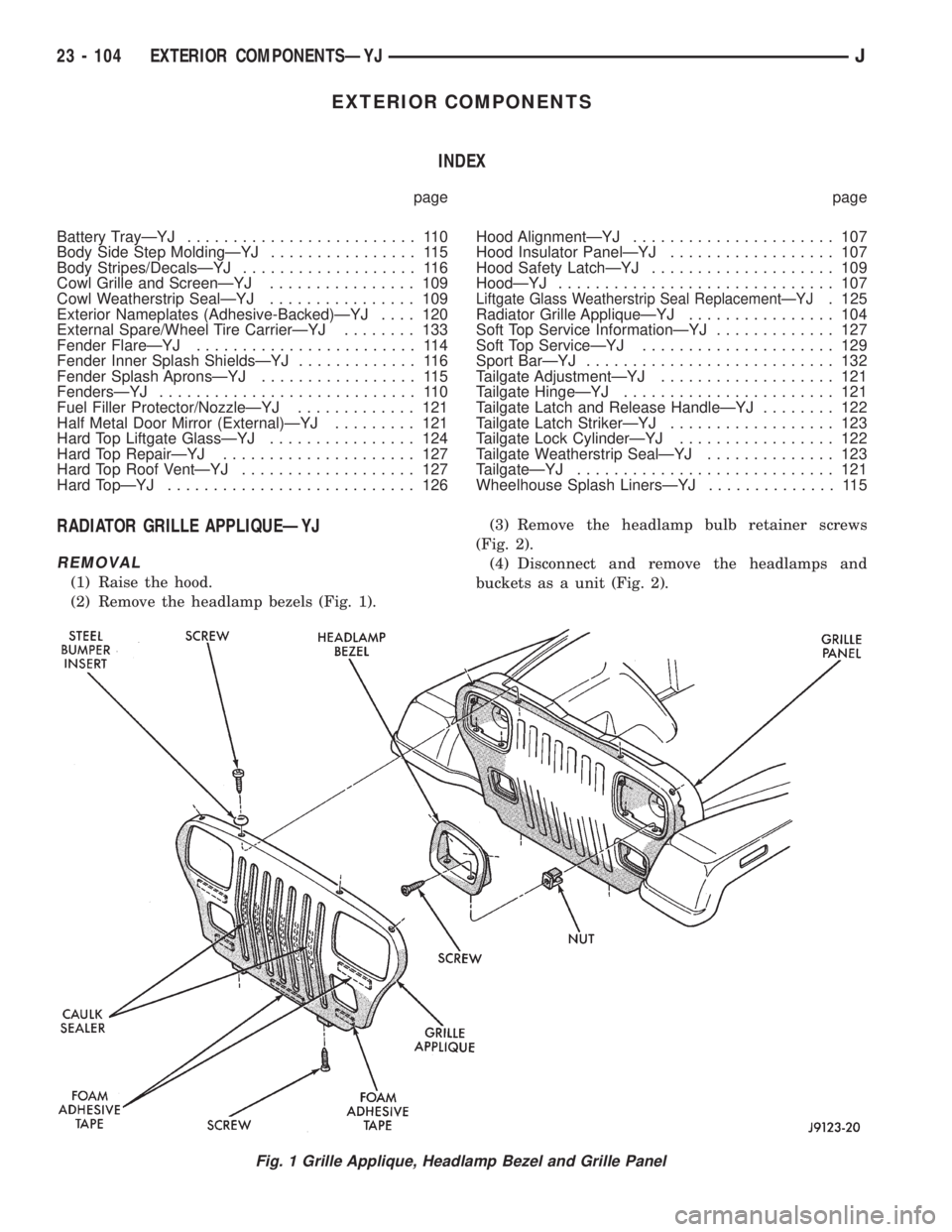
(1) Raise the hood.
(2) Remove the headlamp bezels (Fig. 1).(3) Remove the headlamp bulb retainer screws
(Fig. 2).
(4) Disconnect and remove the headlamps and
buckets as a unit (Fig. 2).
Fig. 1 Grille Applique, Headlamp Bezel and Grille Panel
23 - 104 EXTERIOR COMPONENTSÐYJJ