1995 ACURA TL clutch
[x] Cancel search: clutchPage 936 of 1771

Description
The automatic transmission is a combination of a 3-element torque converter and a dual-shaft electronically controlled
automatic transmission which provides 4 speeds forward and 1 reverse. The entire unit is positioned in line with the engine.
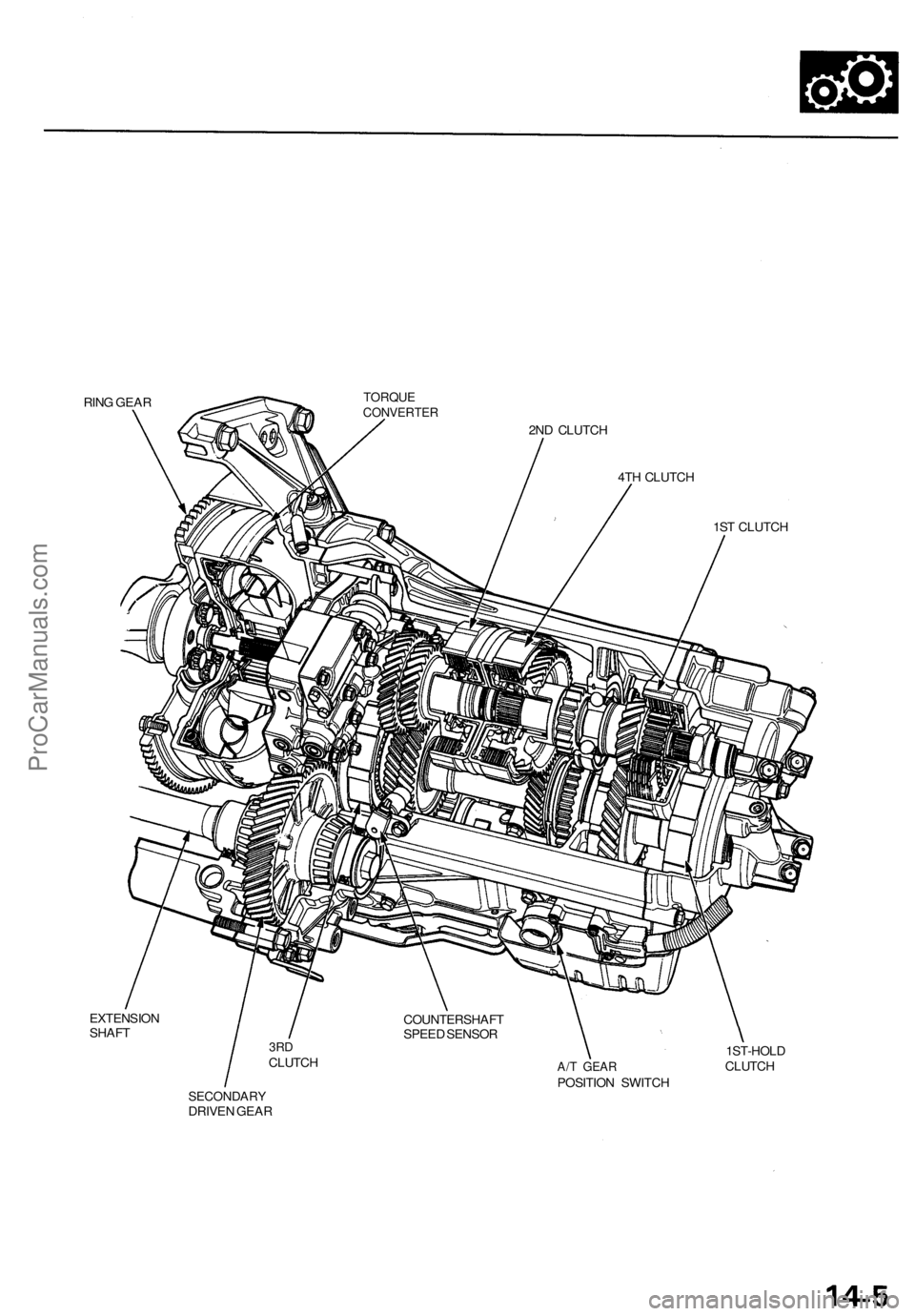
Torque Converter, Gears and Clutches
The torque converter consists of a pump, turbine and stator, assembled in a single unit.
They are connected to the engine crankshaft so they turn together as a unit as the engine turns.
Around the outside of the drive plate is a ring gear which meshes with the starter pinion when the engine is being started.
The entire torque converter assembly serves as a flywheel while transmitting power to the transmission mainshaft.
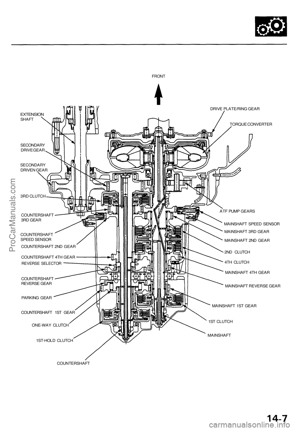
The transmission has two parallel shafts: the mainshaft and the countershaft. The mainshaft is in line with the engine
crankshaft.
The mainshaft includes the 1st, 2nd and 4th clutches, and gears for 4th, 2nd, 1st and reverse (3rd gear is integral with the
mainshaft, while the reverse gear is integral with 4th gear).
The countershaft includes the 3rd, and 1st-hold clutches, and gears for 3rd, 4th, 1st, 2nd, reverse, and parking. The sec-
ondary drive gear is integrated with the countershaft.
The gears on the mainshaft are in constant mesh with those on the countershaft.
When certain combinations of gears in the transmission are engaged by clutches, power is transmitted from the mainshaft
to the countershaft to provide and positions.
Electronic Control
The electronic control system consists of the Transmission Control Module (TCM), sensors, a linear solenoid and four
solenoid valves. Shifting and lock-up are electronically controlled for comfortable driving under all conditions.
The TCM is located below the dashboard, behind the glove box on the passenger's side.
Hydraulic Control
The lower valve body assembly includes the main valve body, the servo body and the shift control solenoid valves. They
are bolted on the lower part of the transmission housing.
Other valve bodies, the regulator valve body, the ATF pump body, the 2nd accumulator body, and the throttle valve body,
are bolted to the torque converter housing.
The main valve body contains the manual valve, the 1 - 2 shift valve, the 2 - 3 shift valve, the 3 - 4 shift valve, the 4th kick-
down valve, the 2 - 3 orifice control valve, the 3 - 4 orifice control valve, the 4th exhaust valve, the servo control valve,
and the main orifice control valve.
The servo body contains the servo valve, 3rd and 4th accumulator pistons.
The regulator valve body contains the regulator valve, the lock-up shift valve, and the cooler relief valve.
Fluid from the regulator passes through the manual valve to the various control valves.
The throttle valve body includes the throttle valve which is bolted onto the 2nd accumulator body. The 2nd accumulator
piston is assembled in the 2nd accumulator body.
The linear solenoid is joined with the throttle valve body.
The ATF pump body contains the modulator valve, the lock-up control valve, the lock-up timing valve, and the relief valve.
The torque converter check valve is located in the torque converter housing under the ATF pump body.
The 1st and 1st-hold accumulator pistons are assembled in the rear cover.
The clutches receive fluid from their respective feed pipes or internal hydraulic circuit.
Shift Control Mechanism
Input from various sensors located throughout the vehicle determines which shift control solenoid valve the TCM will acti-
vate. Activating a shift control solenoid valve changes modulator pressure, causing a shift valve to move. This pressurizes
a line to one of the clutches, engaging that clutch and its corresponding gear.
Lock-up Mechanism
In position, in 2nd, 3rd and 4th, and in position in 3rd, pressurized fluid is drained from the back of the torque con-
verter through a fluid passage, causing the lock-up piston to be held against the torque converter cover. As this takes place,
the mainshaft rotates at the same speed as the engine crankshaft. Together with hydraulic control, the TCM optimizes the
timing of the lock-up mechanism. The lock-up valves control the range of lock-up according to lock-up control solenoid
valves A and B, and throttle valve. When lock-up control solenoid valves A and B activate, the modulator pressure changes.
The lock-up control solenoid valves A and B are mounted on the torque converter housing, and are controlled by the TCM.ProCarManuals.com
Page 937 of 1771
Description
(cont'd)
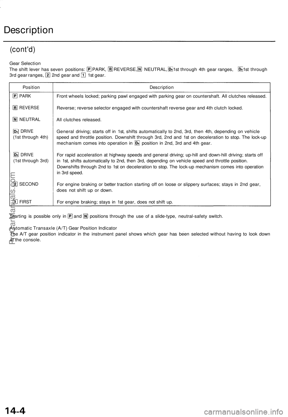
Gear Selectio n
The shif t leve r ha s seve n positions : PARK , REVERSE, NEUTRAL , 1st throug h 4t h gea r ranges , 1s t throug h
3rd gea r ranges , 2n d gea r an d 1s t gear .
Positio nDescriptio n
PARK
REVERS E
NEUTRAL
] DRIV E
(1st throug h 4th )
DRIV E
(1st throug h 3rd )
SECON D
FIRST
Front wheel s locked ; parkin g paw l engage d wit h parkin g gea r o n countershaft . Al l clutche s released .
Reverse ; revers e selecto r engage d wit h countershaf t revers e gea r an d 4t h clutc h locked .
Al l clutche s released .
Genera l driving ; start s of f i n 1st , shift s automaticall y t o 2nd , 3rd , the n 4th , dependin g o n vehicl e
spee d an d throttl e position . Downshif t throug h 3rd , 2n d an d 1s t o n deceleratio n t o stop . Th e lock-u p
mechanis m come s int o operatio n i n positio n i n 2nd , 3r d an d 4t h gear .
Fo r rapi d acceleratio n a t highwa y speed s an d genera l driving ; up-hil l an d down-hil l driving ; start s of f
i n 1st , shift s automaticall y t o 2nd , the n 3rd , dependin g o n vehicl e spee d an d throttl e position .
Downshift s throug h 2n d t o 1s t o n deceleratio n t o stop . Th e lock-u p mechanis m come s int o operatio n
i n 3r d speed .
Fo r engin e brakin g o r bette r tractio n startin g of f o n loos e o r slipper y surfaces ; stay s i n 2n d gear ,
doe s no t shif t u p o r down .
Fo r engin e braking ; stay s i n 1s t gear , doe s no t shif t up .
Startin g i s possibl e onl y i n an d position s throug h th e us e o f a slide-type , neutral-safet y switch .
Automati c Transaxl e (A/T ) Gea r Positio n Indicato r
Th e A/ T gea r positio n indicato r i n th e instrumen t pane l show s whic h gea r ha s bee n selecte d withou t havin g t o loo k dow n
a t th e console .
ProCarManuals.com
Page 938 of 1771
RING GEAR
EXTENSION
SHAFT
TORQUE
CONVERTER
2ND CLUTCH
4TH CLUTCH
1ST CLUTCH
SECONDARY
DRIVEN GEAR
A/T GEAR
POSITION SWITCH
1ST-HOLD
CLUTCH
COUNTERSHAFT
SPEED SENSOR
3RD
CLUTCHProCarManuals.com
Page 939 of 1771
Description
Clutches
The four-spee d automati c transmissio n use s hydraulically-actuate d clutche s t o engag e o r disengag e th e transmissio n gears .
Whe n hydrauli c pressur e i s introduce d int o th e clutc h drum , th e clutc h pisto n moves . Thi s presse s th e frictio n disc s an d
stee l plate s together , lockin g the m s o the y don' t slip . Powe r i s the n transmitte d throug h th e engage d clutc h pac k t o it s
hub-mounte d gear .
Likewise , whe n th e hydrauli c pressur e is ble d fro m th e clutc h pack , th e pisto n release s th e frictio n disc s an d th e stee l plates ,
an d the y ar e fre e t o slid e pas t each . Thi s allow s th e gea r t o spi n independentl y o n it s shaft , transmittin g n o power .
1s t Clutc h
Th e 1s t clutc h engages/disengage s 1s t gear , an d is locate d a t th e en d o f th e mainshaft , jus t behin d th e rea r cover .
Th e 1s t clutc h i s supplie d hydrauli c pressur e b y it s AT F fee d pip e withi n th e mainshaft .
1st-hol d Clutc h
The 1st-hol d clutc h engages/disengages 1st-hold o r position , an d i s locate d a t th e en d o f th e countershaft , jus t behin d
th e rea r cover . Th e 1st-hol d clutc h is supplie d hydrauli c pressur e b y it s AT F fee d pip e withi n th e countershaft .
2n d Clutc h
Th e 2n d clutc h engages/disengage s 2n d gear , an d i s locate d a t th e cente r o f th e mainshaft . Th e 2n d clutc h i s joine d back -
to-bac k t o th e 4t h clutch . Th e 2n d clutc h i s supplie d hydrauli c pressur e throug h th e mainshaf t b y a circui t connecte d t o th e
interna l hydrauli c circuit .
3r d Clutc h
Th e 3r d clutc h engages/disengage s 3r d gear , an d i s locate d a t th e en d o f th e countershaft .
Th e 3r d clutc h i s supplie d hydrauli c pressur e b y it s AT F fee d pip e withi n th e countershaft .
4t h Clutc h
Th e 4t h clutc h engages/disengage s 4t h gear , a s wel l a s revers e gear , an d i s locate d a t th e cente r o f th e mainshaft . Th e 4t h
clutc h i s joine d back-to-bac k t o th e 2n d clutch . Th e 4t h clutc h i s supplie d hydrauli c pressur e b y it s AT F fee d pip e withi n th e
mainshaft .
One-wa y Clutc h
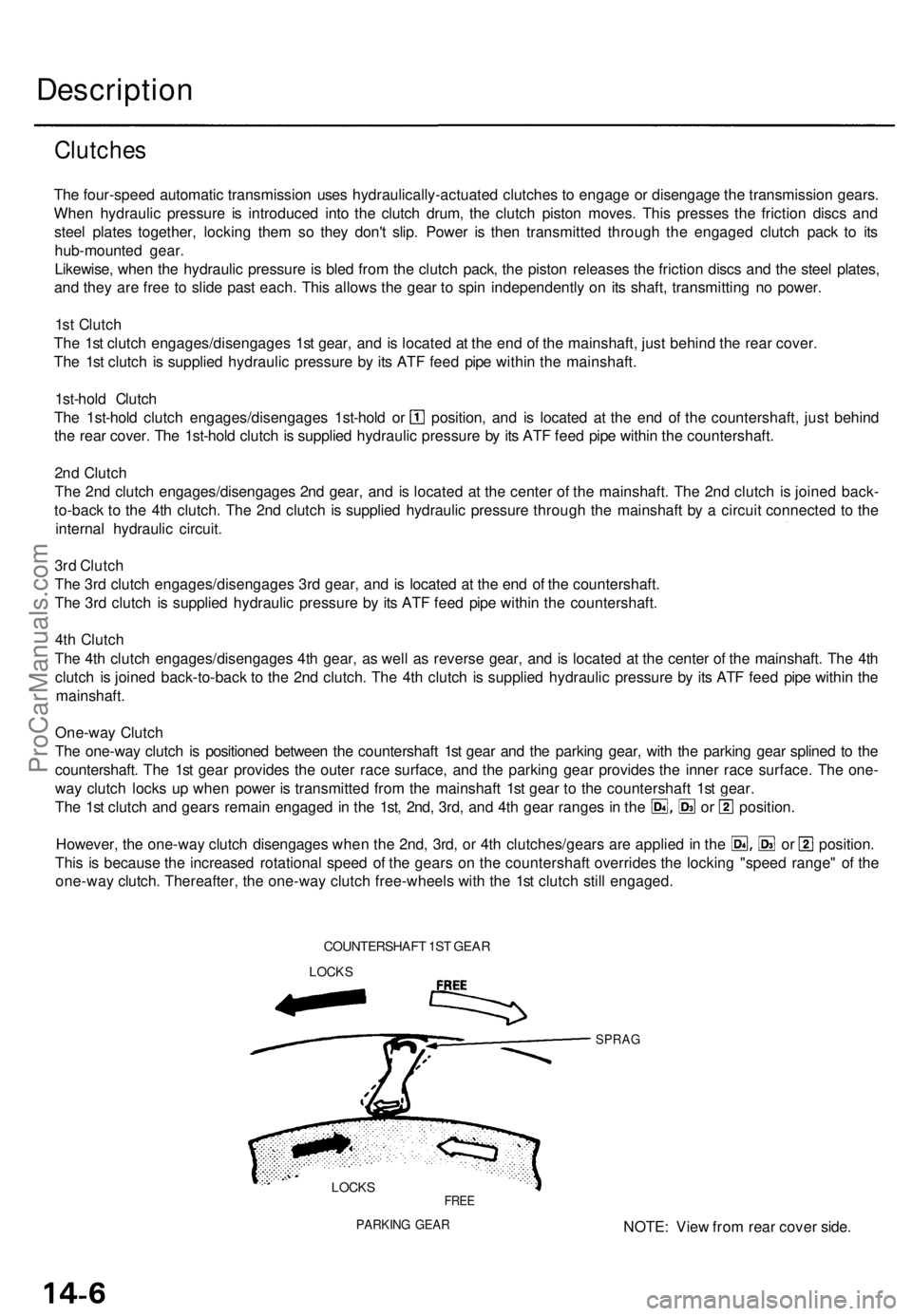
Th e one-wa y clutc h i s positione d betwee n th e countershaf t 1s t gea r an d th e parkin g gear , wit h th e parkin g gea r spline d t o th e
countershaft . Th e 1s t gea r provide s th e oute r rac e surface , an d th e parkin g gea r provide s th e inne r rac e surface . Th e one -
wa y clutc h lock s u p whe n powe r i s transmitte d fro m th e mainshaf t 1s t gea r t o th e countershaf t 1s t gear .
The 1s t clutc h an d gear s remai n engage d in th e 1st , 2nd , 3rd , an d 4t h gea r range s i n th e o r position .
However, th e one-wa y clutc h disengage s whe n th e 2nd , 3rd , o r 4t h clutches/gear s ar e applie d in th e o r position .
Thi s i s becaus e th e increase d rotational speed o f th e gear s o n th e countershaf t override s th e lockin g "spee d range " o f th e
one-wa y clutch . Thereafter , th e one-wa y clutc h free-wheel s wit h th e 1s t clutc h stil l engaged .
COUNTERSHAF T 1S T GEA R
LOCK S
SPRA G
LOCKSFREE
PARKIN G GEA RNOTE : Vie w fro m rea r cove r side .
ProCarManuals.com
Page 940 of 1771
FRONT
EXTENSION
SHAFT
SECONDARY
DRIVE GEAR
SECONDARY
DRIVEN GEAR
3RD CLUTCH
COUNTERSHAFT
3RD GEAR
DRIVE PLATE/RING GEAR
TORQUE CONVERTER
COUNTERSHAFT
SPEED SENSOR
COUNTERSHAFT 2ND GEAR
COUNTERSHAFT 4TH GEAR
REVERSE SELECTOR
COUNTERSHAFT
REVERSE GEAR
PARKING GEAR
COUNTERSHAFT 1ST GEAR
ONE-WAY CLUTCH
1ST-HOLD CLUTCH
MAINSHAFT SPEED SENSOR
MAINSHAFT 3RD GEAR
MAINSHAFT 2ND GEAR
2ND CLUTCH
4TH CLUTCH
MAINSHAFT 4TH GEAR
MAINSHAFT REVERSE GEAR
MAINSHAFT 1ST GEAR
1ST CLUTCH
MAINSHAFT
COUNTERSHAFT
ATF PUMP GEARSProCarManuals.com
Page 942 of 1771
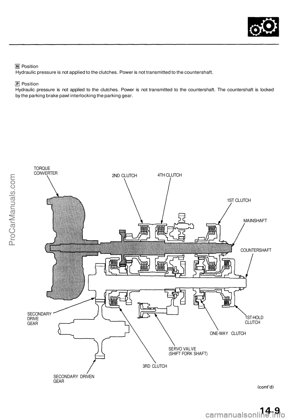
Position
Hydraulic pressure is not applied to the clutches. Power is not transmitted to the countershaft.
Position
Hydraulic pressure is not applied to the clutches. Power is not transmitted to the countershaft. The countershaft is locked
by the parking brake pawl interlocking the parking gear.
TORQUE
CONVERTER
SECONDARY
DRIVE
GEAR
2ND CLUTCH
4TH CLUTCH
1ST CLUTCH
MAINSHAFT
COUNTERSHAFT
1ST-HOLD
CLUTCH
ONE-WAY CLUTCH
SERVO VALVE
(SHIFT FORK SHAFT)
3RD CLUTCH
SECONDARY DRIVEN
GEARProCarManuals.com
Page 943 of 1771
Description
Power Flow (cont'd)
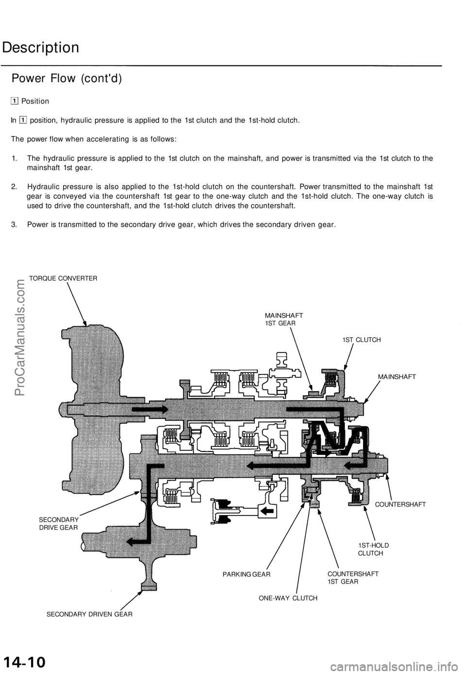
Position
In position, hydraulic pressure is applied to the 1st clutch and the 1st-hold clutch.
The power flow when accelerating is as follows:
1. The hydraulic pressure is applied to the 1st clutch on the mainshaft, and power is transmitted via the 1st clutch to the
mainshaft 1st gear.
2. Hydraulic pressure is also applied to the 1st-hold clutch on the countershaft. Power transmitted to the mainshaft 1st
gear is conveyed via the countershaft 1st gear to the one-way clutch and the 1st-hold clutch. The one-way clutch is
used to drive the countershaft, and the 1st-hold clutch drives the countershaft.
3. Power is transmitted to the secondary drive gear, which drives the secondary driven gear.
TORQUE CONVERTER
MAINSHAFT
1ST GEAR
SECONDARY
DRIVE GEAR
1ST CLUTCH
MAINSHAFT
COUNTERSHAFT
1ST-HOLD
CLUTCH
COUNTERSHAFT
1ST GEAR
ONE-WAY CLUTCH
SECONDARY DRIVEN GEAR
PARKING GEARProCarManuals.com
Page 944 of 1771

Position
The power flow when decelerating is as follows:
1. Rolling resistance from the road surface goes through the front wheels to the secondary drive gear, then to the coun-
tershaft 1st gear via the 1st-hold clutch which is applied during deceleration.
2. The one-way clutch disengages at this time because the application of torque is reversed.
3. The counterforce conveyed to the countershaft 1st gear turns the mainshaft 1st gear. At this time, since hydraulic
pressure is also applied to the 1st clutch, counterforce is also transmitted to the mainshaft. As a result, engine braking
can be obtained with 1st gear.
TORQUE CONVERTER
MAINSHAFT 1ST GEAR
1ST CLUTCH
MAINSHAFT
SECONDARY
DRIVE GEAR
COUNTERSHAFT
1ST-HOLD
CLUTCH
COUNTERSHAFT
1ST GEAR
SECONDARY DRIVEN GEARProCarManuals.com