Page 970 of 1771
Description
B Position
The flow of fluid through the torque converter circuit is the same as in position.
The line pressure (1) becomes the line pressure (3) and flows to the 1-2 shift valve. The line pressure (3) becomes line
pressure (3') at the 1-2 shift valve and flows to the servo valve. The servo valve is moved to the right side (Reverse range
position) and uncovers the port to allow line pressure (3") to the manual valve as in position. The line pressure (3")
from the servo valve is intercepted by the manual valve.
However, hydraulic pressure is not supplied to the clutches, and power is not transmitted.
NOTE: When used, "left" or "right" indicates direction on the hydraulic circuit.
Hydraulic Flow (cont'd)ProCarManuals.com
Page 994 of 1771

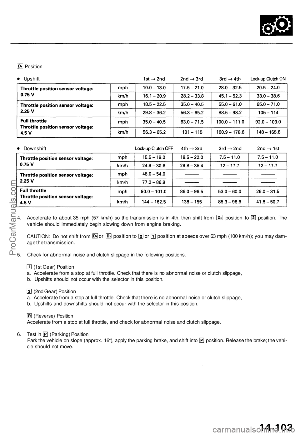
Position
Upshift
Downshift
4. Accelerate to about 35 mph (57 km/h) so the transmission is in 4th, then shift from position to position. The
vehicle should immediately begin slowing down from engine braking.
CAUTION: Do not shift from
age the transmission.
or position to or position at speeds over 63 mph (100 km/h); you may dam-
5. Check for abnormal noise and clutch slippage in the following positions.
(1st Gear) Position
a. Accelerate from a stop at full throttle. Check that there is no abnormal noise or clutch slippage,
b. Upshifts should not occur with the selector in this position.
(2nd Gear) Position
a. Accelerate from a stop at full throttle. Check that there is no abnormal noise or clutch slippage,
b. Upshifts and downshifts should not occur with the selector in this position.
(Reverse) Position
Accelerate from a stop at full throttle, and check for abnormal noise and clutch slippage.
6. Test in (Parking) Position
Park the vehicle on slope (approx. 16°), apply the parking brake, and shift into position. Release the brake; the vehi-
cle should not move.ProCarManuals.com
Page 1021 of 1771
Rear Cover
Removal
NOTE:
Clean all parts thoroughly in solvent or carburetor cleaner, and dry with compressed air.
Blow out all passages.
When removing the rear cover, replace the following:
O-rings
Mainshaft and countershaft locknuts
Conical spring washers
LOCKNUTS
Replace.
Mainshaft locknut has left-hand threads.
CONICAL SPRING
WASHER
Replace.
1ST-HOLD CLUTCH
ASSEMBLY
THRUST WASHER
THRUST NEEDLE
BEARING
1 ST-HOLD CLUTCH
HUB
1ST GEAR
ONE-WAY CLUTCH
NEEDLE BEARINGS
1ST GEAR COLLAR
PARKING GEAR
COUNTERSHAFT
MAINSHAFT
CONICAL SPRING
WASHER
Replace.
1ST CLUTCH
ASSEMBLY
THRUST WASHER
•THRUST NEEDLE
BEARING
NEEDLE BEARING
1ST GEAR
THRUST WASHER
1ST GEAR COLLAR
6 x 1.0 mm Bolt
8 Bolts
REAR COVER
DOWEL PINS
REAR COVER
GASKET
Replace.
ATF FEED PIPES, 4
A/T GEAR POSITION
SWITCH HARNESS
6 x 1.0 mm BoltProCarManuals.com
Page 1022 of 1771

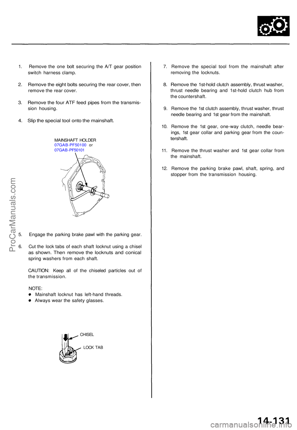
1. Remov e th e on e bol t securin g th e A/ T gea r positio n
switc h harnes s clamp .
2. Remov e th e eigh t bolt s securin g th e rea r cover , the n
remov e th e rea r cover .
3. Remov e th e fou r AT F fee d pipe s fro m th e transmis -
sion housing .
4. Sli p th e specia l too l ont o th e mainshaft .
MAINSHAF T HOLDE R07GAB-PF5010 0 o r07GA B-PF5010 1
5. Engag e th e parkin g brak e paw l wit h th e parkin g gear .
6 . Cu t th e loc k tab s o f eac h shaf t locknu t usin g a chise l
as shown . The n remov e th e locknut s an d conica l
spring washer s fro m eac h shaft .
CAUTION : Kee p al l o f th e chisele d particle s ou t o f
th e transmission .
NOTE :
Mainshaf t locknu t ha s left-han d threads .
Alway s wea r th e safet y glasses . 7
. Remov e th e specia l too l fro m th e mainshaf t afte r
removin g th e locknuts .
8. Remov e th e 1st-hol d clutc h assembly , thrus t washer ,
thrust needl e bearin g an d 1st-hol d clutc h hu b fro m
th e countershaft .
9 . Remov e th e 1s t clutc h assembly , thrus t washer , thrus t
needl e bearin g an d 1s t gea r fro m th e mainshaft .
10 . Remov e th e 1s t gear , one-wa y clutch , needl e bear -
ings , 1s t gea r colla r an d parkin g gea r fro m th e coun -
tershaft .
11. Remov e th e thrus t washe r an d 1s t gea r colla r fro m
th e mainshaft .
12 . Remov e th e parkin g brak e pawl , shaft , spring , an d
stoppe r fro m th e transmissio n housing .
LOCK TA B
CHISE L
ProCarManuals.com
Page 1041 of 1771
Mainshaft
Inspection (cont'd)
6. Measure the 2nd gear axial clearance while pushing
the 4th/2nd clutch toward the 1st clutch.
STANDARD: 0.07 - 0.15 mm (0.003 - 0.006 in)
NOTE: Take measurements in at least three places,
and use the average as the actual clearance.
7. If the clearance is out of tolerance, remove the 2nd
gear thrust washer and measure its thickness.
8. Select and install a new 2nd gear thrust washer,
then recheck.
2ND GEAR THRUST WASHER, 37.5 x 56 mm
9. After replacing the 2nd gear thrust washer, make
sure that the clearance is within tolerance.ProCarManuals.com
Page 1048 of 1771
Clutch
Illustrated Index
1ST-HOLD CLUTCH
3RD CLUTCH
CLUTCH DRUM
O-RINGS
Replace.
CLUTCH PISTON
CHECK VALVE
RETURN SPRING
SPRING RETAINER
SNAP RING
CLUTCH PLATES
Standard thickness:
2.00 mm (0.079 in)
CLUTCH END PLATE
CLUTCH DISCS
Standard thickness:
1.94 mm (0.076 in)
CLUTCH DISCS
Standard thickness:
1.94 mm (0.076 in)
CLUTCH PISTON
SNAP RING
CLUTCH END PLATE
CLUTCH PLATES
Standard thickness:
2.00 mm (0.079 in)
SNAP RING
SPRING RETAINER
RETURN SPRING
DISC SPRING
Install in this direction.
CLUTCH DRUM
O-RINGS
Replace.
SNAP RINGProCarManuals.com
Page 1049 of 1771
Clutch
Illustrated Index (cont'd)
4TH/2ND CLUTCH
O-RINGS
Replace.
CLUTCH PISTON
CHECK VALVE
RETURN SPRING
SPRING RETAINER
SNAP RING
CLUTCH PLATES
Standard thickness:
2.30 mm (0.091 in)
CLUTCH END PLATE
SNAP RING
CLUTCH DISCS
Standard thickness
1.94 mm (0.076 in)
DISC SPRING
Install in this direction.
CLUTCH DISCS
Standard thickness:
1.94 mm (0.076 in)
CLUTCH PISTON
SNAP RING
CLUTCH END PLATE
CLUTCH PLATES
Standard thickness:
2.30 mm (0.091 in)
SPRING RETAINER
RETURN SPRING
DISC SPRING
Install in this direction.
4TH CLUTCH DRUM
2ND CLUTCH DRUM
O-RINGS
Replace.
SNAP RINGProCarManuals.com
Page 1050 of 1771
1ST CLUTC H
CHECK VALV E
SPRIN G RETAINE R
RETUR N SPRIN G
SNA P RIN G
CLUTC H PLATE S
Standar d thickness :
2.0 0 m m (0.07 9 in ) CLUTC
H DRU M
O-RING S
Replace .
CLUTCH PISTO N
DIS C SPRIN G
Install i n thi s direction .
CLUTCH DISC SStandar d thickness :1.94 m m (0.07 6 in )
CLUTC H EN D PLAT E
SNA P RIN G
ProCarManuals.com