1995 ACURA TL clutch
[x] Cancel search: clutchPage 401 of 1771

6. Instal l th e specia l tool s a s shown .
NOTE : Fo r 2nd , 3rd , 1st-hol d an d revers e clutche s
CLUTCH SPRIN GCOMPRESSO RBOLT ASSEMBL Y
07GA E - PG4020 0 o r
07")
Clutch
Reassembl y (cont'd )
6. Instal l th e specia l tool s a s shown .
NOTE : Fo r 2nd , 3rd , 1st-hol d an d revers e clutche s
CLUTCH SPRIN GCOMPRESSO RBOLT ASSEMBL Y
07GA E - PG4020 0 o r
07GA E - PG4020 A
NOTE: For Islan d 4th clutche s
CLUTCH SPRIN GCOMPRESSO RBOLT ASSEMBL Y
07GA E - PG4020 0 o r
07GA E - PG4020 A CLUTC
H SPRIN G
COMPRESSO R
ATTACHMENT07LAE-PX4010 0
CLUTCH SPRIN GCOMPRESSO RATTACHMENT07LAE-PX40100 or07HA E - PL5010 1
CLUTC H SPRIN G
COMPRESSO RATTACHMENT
07LA E - PX4010 0
CLUTC H SPRIN G
COMPRESSO RATTACHMENT
07LAE-PX40100 or
07HA E - PL5010 1
CAUTION : I f eithe r en d o f th e specia l too l i s se t
ove r a n are a o f th e sprin g retaine r whic h i s unsup -
porte d b y th e retur n spring , th e retaine r ma y b e
damaged . B e sur e th e specia l too l i s adjuste d t o
hav e ful l contac t wit h th e sprin g retainer .
SPECIAL TOO L
Set here .
Do no t se t here .
SPECIA L TOO L
SPRIN G RETAINE R
7. Compres s th e retur n sprin g wit h th e specia l tool .
ProCarManuals.com
Page 402 of 1771
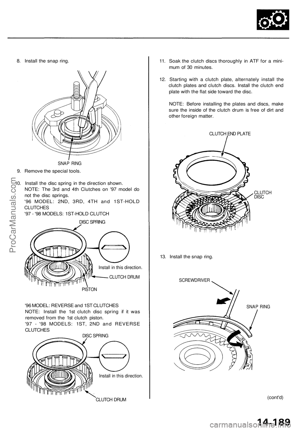
8. Install the snap ring.
SNAP RING
9. Remove the special tools.
10. Install the disc spring in the direction shown.
NOTE: The 3rd and 4th Clutches on '97 model do
not the disc springs.
'96 MODEL: 2ND, 3RD, 4TH and 1ST-HOLD
CLUTCHES
'97 - '98 MODELS: 1ST-HOLD CLUTCH
DISC SPRING
Install in this direction.
CLUTCH DRUM
PISTON
'96 MODEL: REVERSE and 1ST CLUTCHES
NOTE: Install the 1st clutch disc spring if it was
removed from the 1st clutch piston.
'97 - '98 MODELS: 1ST, 2ND and REVERSE
CLUTCHES
DISC SPRING
Install in this direction.
CLUTCH DRUM
11. Soak the clutch discs thoroughly in ATF for a mini-
mum of 30 minutes.
12. Starting with a clutch plate, alternately install the
clutch plates and clutch discs. Install the clutch end
plate with the flat side toward the disc.
NOTE: Before installing the plates and discs, make
sure the inside of the clutch drum is free of dirt and
other foreign matter.
CLUTCH END PLATE
CLUTCH
DISC
13. Install the snap ring.
SCREWDRIVER
SNAP RING
(cont'd)ProCarManuals.com
Page 403 of 1771

14. Measur e th e clearanc e betwee n th e clutc h en d plat e
and to p dis c wit h a dia l indicator .
Zero th e dia l indicato r wit h th e clutc h en d plat e low")
Clutch
Reassembl y (cont'd )
14. Measur e th e clearanc e betwee n th e clutc h en d plat e
and to p dis c wit h a dia l indicator .
Zero th e dia l indicato r wit h th e clutc h en d plat e low -
ered , an d lif t i t u p to th e sna p ring . Th e distanc e tha t
the clutc h en d plat e move s is th e clearanc e betwee n
the clutc h en d plat e an d to p disc .
NOTE : Measur e a t thre e locations .
Clutch En d Plate-to-To p Disc Clearance :
Clutch
1st
2n d
3rd
4th
1st-hol d
Revers e
Service Limi t
0.65
0.6 0
0.6 0
0.50
0.7 0
0.7 5
-0.8 5
-0.80
-0.8 0
-0.70
-0.9 0
-0.9 5
mm
m m
m m
mm
m m
m m
(0
( 0
( 0
(0
02 6
02 4
02 4
020
(0.02 8
(003 0
- 0.03 3
-0.031
-0.03 1
- 0.02 8
- 0.03 5
- 0.03 7
in)
in)
in)
in)
in )
in )
DIA L INDICATO R
TOP DIS C
15. I f th e clearanc e is no t withi n th e servic e limits , selec t
a ne w clutc h en d plat e fro m th e followin g table .
NOTE : I f th e thickes t clutc h en d plat e i s installed ,
but th e clearanc e i s stil l ove r th e standard , replac e
the clutc h disc s an d clutc h plates .
PLATE NUMBE RThicknes s
CLUTCH EN D PLAT E
1ST, 2ND , 3R D an d 4T H CLUTC H EN D PLATE S
Plat e No .
1
2
3
4
5
6
7
8
9
Part Numbe r
2255 1-PY4 - 003
2255 2 - PY 4 - 00 3
2255 3 - PY 4 - 00 3
2255 4 - PY 4 - 00 3
2255 5 - PY 4 - 00 3
2255 6 - PY 4 - 00 3
2255 7 - PY 4 - 00 3
2255 8 - PY 4 - 00 3
2255 9 - PY 4 - 00 3 Thicknes
s
2. 1 m m (0.08 3 in )
2. 2 m m (0.08 7 in )
2. 3 m m (0.09 1 in )
2.4m m (0.09 4 in )
2. 5 m m (0.09 8 in )
2. 6 m m (0.10 2 in )
2. 7 m m (0.10 6 in )
2.8m m (0.1 10 in )
2.9 m m (0. 1 14 in )
1ST-HOL D CLUTCH EN D PLATE S
Plat e No .
L1
L 2
L3
L 4
L5
L 6
L7
L 8
L 9
Par t Numbe r
2235 1 - PY 4 - 00 3
2235 2 - PY 4 - 00 3
2235 3 - PY 4 - 00 3
2235 4 - PY 4 - 00 3
2235 5 - PY 4 - 00 3
2235 6 - PY 4 - 00 3
2235 7 - PY 4 - 00 3
2235 8 - PY 4 - 00 3
2235 9 - PY 4 - 00 3 Thicknes
s
2.1 m m (0.08 3 in )
2.2 m m (0.08 7 in )
2. 3 m m (0.09 1 in )
2. 4 m m (0.09 4 in )
2.5 m m (0.09 8 in )
2.6 m m (0.10 2 in )
2. 7 m m (0.10 6 in )
2. 8 m m (0.11 0 in )
2. 9 m m (0.11 4 in )
REVERS E CLUTC H EN D PLATE S
Plat e No .
R1
R 2
R3
R 4
R5
R6
R7
R 8
R9
Par t Numbe r
2245 1 - PY 4 - 00 3
2245 2 - PY 4 - 00 3
2245 3 - PY 4 - 00 3
2245 4 - PY 4 - 00 3
2245 5 - PY 4 - 00 3
2245 6 - PY 4 - 00 3
2245 7 - PY 4 - 00 3
2245 8 - PY 4 - 00 3
2245 9 - PY 4 - 00 3 Thicknes
s
4. 1 m m (0.16 1 in )
4. 2 m m (0.16 5 in )
4. 3 m m (0.16 9 in )
4. 4 m m (0.17 3 in )
4. 5 m m (0.17 7 in )
4. 6 m m (0.18 1 in )
4. 7 m m (0.18 5 in )
4. 8 m m (0.18 9 in )
4. 9 m m (0.19 3 in )
SNA P RING
CLUTC H EN DPLAT EClearanc e
ProCarManuals.com
Page 419 of 1771

17. Install the mainshaft sub-assembly and the counter-
shaft sub-assembly together in the torque converter
housing.
NOTE: Take care to prevent damage to the")
Transmission
Reassembly (cont'd)
17. Install the mainshaft sub-assembly and the counter-
shaft sub-assembly together in the torque converter
housing.
NOTE: Take care to prevent damage to the regula-
tor valve body, when installing the shafts.
COUNTERSHAFT
SUB-ASSEMBLY
MAINSHAFT
SUB-ASSEMBLY
18. Install the two dowel pins and a new gasket on the
torque converter housing.
TRANSMISSION HOUSING
BOLTS
TRANSMISSION 8 x 1.25 mm
HOUSING
33 N-m (3.4 kgf-m, 25 Ibf-ft)
DOWEL
PIN
COUNTERSHAFT
SPEED SENSOR
WASHER
COUNTERSHAFT
SPEED SENSOR
6x 1.0 mm
12 N-m
(1.2 kgf-m,
8.7 Ibf-ft)
MAINSHAFT
SPEED SENSOR
WASHER
TRANSMISSION
HOUSING
GASKET
DOWEL PIN
MAINSHAFT
SPEED SENSOR
19. Place the transmission housing on the torque con-
verter housing.
CAUTION: Make sure that the mainshaft and
countershaft speed sensors are not installed on the
transmission housing before installing the transmis-
sion housing on the torque converter housing.
20. Install the transmission housing mounting bolts with
the transmission hanger, harness clamp bracket,
and speed sensor connector bracket, then tighten
them in two or more steps in the sequence shown.
TORQUE: 33 N-m (3.4 kgf-m, 25 Ibf-ft)
TRANSMISSION HANGER
HARNESS CLAMP BRACKET
SPEED SENSOR
CONNECTOR
BRACKET
21. Install the mainshaft and countershaft speed sen-
sors with the washers on the transmission housing.
22. Install the countershaft 2nd gear assembly, 2nd gear
one-way clutch, needle bearings, thrust washer, and
thrust needle bearing on the countershaft.
THRUST NEEDLE
BEARING
THRUST WASHER,
45.5
x 60 mm
NEEDLE BEARINGS
2ND GEAR ONE-WAY
CLUTCH
NEEDLE BEARING
THRUST NEEDLE
BEARING
2ND GEAR
COLLAR
MAINSHAFT
23. Install the 2nd gear collar, thrust needle bearing,
and needle bearing on the mainshaft.
2ND GEAR
ASSEMBLY
COUNTERSHAFTProCarManuals.com
Page 420 of 1771

24. Combin e th e mainshaf t 2n d gea r wit h th e parkin g
gear, the n instal l the m o n thei r respectiv e shafts .
MAINSHAF T
MAINSHAF T
2ND GEA R
COUNTERSHAF T
PARKING GEA R
25. Ta p th e parkin g gea r ver y lightl y t o instal l i n th e 2n d
gea r one-wa y clutch , usin g th e specia l too l a s
shown .
DRIVE R I.D .40 m m07746-003010 0
MAINSHAFTPARKING
GEA R
26. Instal l th e parkin g brak e paw l shaft , spring , pawl ,
and sleev e i n th e transmissio n housin g (se e pag e
14-200 ).
27 . Instal l th e AT F fee d pip e i n th e accumulato r cover .
ATF FEE D PIP E
ACCUMULATO R
COVE R
28. Instal l th e revers e clutc h distanc e colla r an d a ne w
countershaf t conica l sprin g washe r o n th e counter -
shaft .
NOTE : Instal l th e conica l sprin g washer s i n th e
directio n shown .
24 m m WASHE R
BAL L BEARING
THRUS T NEEDL E
BEARIN G
REVERS E GEA R
THRUS T NEEDL E
BEARIN G
NEEDL E BEARIN G
REVERS E GEA R
COLLA R
O-RING S
Replace .
CONICA L SPRIN G
WASHE R
REVERS E CLUTC H
DISTANC E COLLA R
COUNTERSHAF TREVERS
E CLUTC H
ASSEMBL Y
24 m m WASHE R
BAL L BEARIN G
REVERS E GEA R
REVERS E GEA R
DISTANC ECOLLAR
CONICA L SPRIN G
WASHE R
2ND CLUTC HASSEMBL Y
O-RING S
Replace .
29 m m THRUS T
WASHE R
MAINSHAF T THRUS T NEEDL EBEARIN G
29. Instal l th e thrus t needl e bearin g an d 2 9 m m thrus t
washe r o n th e mainshaft .
30 . Instal l ne w O-ring s o n th e countershaf t an d main -
shaft .
NOTE : Befor e installin g th e O-rings , wra p th e shaf t
spline s wit h tap e t o preven t damag e t o th e O-rings .
31 . Instal l th e 2n d clutc h assembl y o n th e mainshaft ,
the n instal l th e revers e clutc h assembly , revers e
gea r collar , needl e bearing , thrus t needl e bearing ,
revers e gear , thrus t needl e bearing , 2 5 m m thrus t
washe r an d bal l bearin g o n th e countershaft .
32 . Instal l a ne w mainshaf t conica l sprin g washer ,
revers e gea r distanc e collar , revers e gea r an d bal l
bearin g o n th e mainshaft .
25 m m THRUS TWASHER
ProCarManuals.com
Page 585 of 1771

Check for Wear and Damage
The starter should crank the engine smoothly and steadily.
If the starter engages, but cranks the engine erratically,
remove it, and inspect the starter drive gear and torque
converter ring gear for damage.
• Check the drive gear overrunning clutch for binding
or slipping when the armature is rotated with the
drive gear held. If the clutch is damaged, replace the
clutch assembly.
Check Cranking Voltage and Current Draw
Cranking voltage should be no less than 8.0 volts.
Current draw should be no more than 450 amperes.
If cranking voltage is too low, or current draw too high,
check for:
Dead or low battery
Open circuit in starter armature commutator segments
Starter armature dragging
Shorted armature winding
Excessive drag in engine
Check Cranking rpm
Engine speed during cranking should be above 100 rpm.
If speed is too low, check for:
Loose battery or starter terminals
Excessively worn starter brushes
Open circuit in commutator segments
Dirty or damaged helical spline or drive gear
Defective drive gear overrunning clutch
Check Starter Disengagement
With the shift lever in or , turn the ignition switch to
"START (III)", and release to "ON (II)". The starter drive
gear should disengage from the flywheel ring gear when
you release the key.
If the drive gear hangs upon the flywheel ring gear, check
for:
• Solenoid plunger and switch malfunction
• Dirty drive gear assembly or damaged overrunning
clutchProCarManuals.com
Page 877 of 1771

OUTPUTS
Fuel Injectors
PGM-FI Main Relay (Fuel Pump)
MIL
IAC Valve
A/C Compressor Clutch Relay
Radiator Fan Relay
Conden")
PGM-FI System
System Description
INPUTS
ENGINE CONTROL MODULE (ECM)
OUTPUTS
Fuel Injectors
PGM-FI Main Relay (Fuel Pump)
MIL
IAC Valve
A/C Compressor Clutch Relay
Radiator Fan Relay
Condenser Fan Relay
ALT
ICM
EVAP Purge Control Solenoid
Valve
Primary HO2S Heater
Secondary H02S Heater
EGR Control Solenoid Valve
IAB Control Solenoid Valve
EVAP Bypass Solenoid Valve*2
EVAP Control Canister Vent Shut
Valve*2
*1: '95-96 models
*2: '97 - 98 models
PGM-FI System
The PGM-FI system on this model is a sequential multiport fuel injection system.
Fuel injector Timing and Duration
The ECM contains memories for the basic discharge durations at various engine speeds and manifold air flow rates. The
basic discharge duration, after being read out from the memory, is further modified by signals sent from various sensors
to obtain the final discharge duration.
Idle Air Control
Idle Air Control Valve (IAC Valve)
When the engine is cold, the A/C compressor is on, the transmission is in gear, the brake pedal is depressed, the P/S load
is high, or the alternator is charging, the ECM controls current to the IAC Valve to maintain the correct idle speed.
Ignition Timing Control
• The ECM contains memories for basic ignition timing at various engine speeds and manifold air flow rates. Ignition
timing is also adjusted for engine coolant temperature.
• A knock control system is also used. When detonation is detected by a knock sensor (KS), the ignition timing is retarded.
Other Control Functions
1. Starting Control
When the engine is started, the ECM provides a rich mixture by increasing fuel injector duration.
2. Fuel Pump Control
• When the ignition switch is initially turned on, the ECM supplies ground to the PGM-FI main relay that supplies
current to the fuel pump for two seconds to pressurize the fuel system.
• When the engine is running, the ECM supplies ground to the PGM-FI main relay that supplies current to the fuel pump.
• When the engine is not running and the ignition is on, the ECM cuts ground to the PGM-FI main relay which cuts
current to the fuel pump.
3. Fuel Cut-off Control
• During deceleration with the throttle valve closed, current to the fuel injectors is cut off to improve fuel economy at
speeds over 1,250 rpm.
• Fuel cut-off action also takes place when engine speed exceeds 7,100 rpm, regardless of the position of the throttle
valve, to protect the engine from over-revving.
CKP/TDC/CYP Sensor
CKF Sensor
MAF Sensor
ECT Sensor
IAT Sensor
TP Sensor
EGR Valve Lift Sensor
Primary HO2S
Secondary H02S
VSS
BARO Sensor
ELD
Front KS
Rear KS
Starter Signal
ALT FR Signal
Air Conditioning Signal
A/T Gear Position Signal
Battery Voltage (IGN.1)
Brake Switch Signal
PSP Switch Signal
EVAP Purge Flow Switch*1
Fuel Tank Pressure Sensor*2ProCarManuals.com
Page 887 of 1771

I s ther e a clickin g nois e fro m
th e A/ C compresso r clutch ?
Chec k th e A/ C operation :
1 . Star t th e engine .
2 . Tur n th e blowe r switc h ON .
3 . Tur n th e A/ C")
(From pag e 11-108 )
I s ther e a clickin g nois e fro m
th e A/ C compresso r clutch ?
Chec k th e A/ C operation :
1 . Star t th e engine .
2 . Tur n th e blowe r switc h ON .
3 . Tur n th e A/ C switc h ON .
Doe s th e A/ C operate ?
Ai r conditionin g signa l i s OK . Chec
k fo r a n ope n i n th e wire
(AC C line) :Momentaril y connec t th e A/ C
clutc h rela y connecto r termina l
No. 2 to bod y groun d wit h ajumpe r wir e severa l times . A/
C CLUTC H RELA Y CONNECTO R (C328 )JUMPE RWIRE
Wire sid e o f
femal e terminal s
I s ther e a clickin g nois e fro m
th e A/ C compresso r clutch ? Se
e ai r conditione r inspectio n
(se e sectio n 22 ).
Repai r ope n i n th e wir e betwee n
th e EC M (A8 ) an d th e A/ C clutc h
relay.
ECM CONNECTOR S
A (26P)B (16P)
Chec k fo r a n ope n i n th e wir e
(AC C line) :
Measur e voltag e betwee n EC M
connecto r terminal s A2 6 an d B3 . Wir
e sid e o f femal e terminal s
I s voltag e les s tha n 1. 0 V ? Repai
r ope n i n th e wir e betwee n
th e EC M (B3 ) an d th e A/ C switch .
Substitut e a known-goo d EC M
an d recheck . I f symptom/indi -
catio n goe s away , replac e th e
origina l ECM .
Se e th e ai r conditione r inspec -
tion (se e sectio n 22 ).
ProCarManuals.com