Page 1526 of 1771
Compressor
Clutch Overhau l
1. Remov e th e cente r bol t whil e holdin g th e pressur e
plate .
CENTE R BOL T
13. 2 N- m (1.3 5 kgf-m , 9.7 6 Ibf-ft )
A/ C CLUTC H HOLDE R
Commerciall y availabl e
Robinair : P/ N 1020 4
Kent-Moore : P/ N J3787 2
2. Remov e th e pressur e plat e an d shim(s) , takin g car e
no t t o los e th e shim(s) .
PRESSUR E PLAT E
SHIM(S )
3. Remov e th e sna p rin g B wit h sna p rin g pliers , the n
remov e th e pulley .
NOTE:
Be carefu l no t t o damag e th e pulle y an d com -
presso r durin g removal/installation .
Onc e th e sna p rin g B is removed , replac e i t wit h
a ne w one .
SNA P RIN G B
Replace .
PULLEY
ProCarManuals.com
Page 1540 of 1771
Relay and Control Unit Locations
Engine Compartment (cont'd)
INTERMITTENT WIPER
RELAY
Wire colors: BLU/YEL, GRN/YEL,
BLK, GRN/BLK and BLU/WHT
A/C COMPRESSOR CLUTCH RELAY
Wire colors: RED/BLU, RED,
YEL/BLK and WHT
CONDENSER FAN RELAY
Wire colors: LT GRN/YEL,
WHT/GRN, YEL/WHT and WHT
RADIATOR FAN RELAY
Wire colors: LT GRN/YEL,
WHT/BLU, YEL and WHTProCarManuals.com
Page 1557 of 1771

Check for Wear and Damage
The starter should crank the engine smoothly and steadily.
If the starter engages, but cranks the engine erratically,
remove it, and inspect the starter drive gear and torque
converter ring gear for damage.
Check the drive gear overrunning clutch for binding or
slipping when the armature is rotated with the drive
gear held. If the clutch is damaged, replace the clutch
assembly.
Check Cranking Voltage and Current Draw
Cranking voltage should be no less than 8.5 volts.
Current draw should be no more than 380 amperes.
If cranking voltage is too low, or current draw too high,
check for:
Dead or low battery
Open circuit in starter armature commutator segments
Starter armature dragging
Shorted armature winding
Excessive drag in engine
Check Cranking rpm
Engine speed during cranking should be above 100 rpm.
If speed is too low, check for:
Loose battery or starter terminals
Excessively worn starter brushes
Open circuit in commutator segments
Dirty or damaged helical spline or drive gear
Defective drive gear overrunning clutch
Check Starter Disengagement
With the shift lever in turn the ignition switch to
"START (III)", and release to "ON (II)". The starter drive
gear should disengage from the drive plate/ring gear
when you release the key.
If the drive gear hangs up on the drive plate/ring gear,
check for:
• Solenoid plunger and switch malfunction
• Dirty drive gear assembly or damaged overrunning
clutchProCarManuals.com
Page 1560 of 1771
Starter Overhau l
CAUTION: Befor e removin g th e starter , disconnec t th e
negativ e cabl e fro m th e battery .
STARTE R
SOLENOI D
SOLENOI D
LEVER
STARTE RSOLENOI DTest, pag e 23-7 3
OVERRUNNIN GCLUTCH ASSEMBL Y
RUBBE R SEA L
MOLYBDENU M
DISULFID E
TERMINA L COVE R
BRUSH HOLDE R
Test , pag e 23-7 8
ARMATUR EInspection an d
Test , pag e 23-7 6
ARMATUR E HOUSIN G
wit h PERMANEN T
MAGNET
GEAR HOUSIN G
VEN T
TUBE
S TERMINA L WIR E
GEAR HOUSIN G
COVER
OVERRUNNIN GCLUTCH ASSEMBL YInspection, pag e 23-7 9
GASKE
T
BRUSH HOLDE R
ARMATUR E
SOLENOIDLEVER
BRUS HInspection ,
pag e 23-7 8
BRACKE T
END COVE R
MOLYBDENU MDISULFIDE
ProCarManuals.com
Page 1717 of 1771

Cruise Control
Description (cont'd)
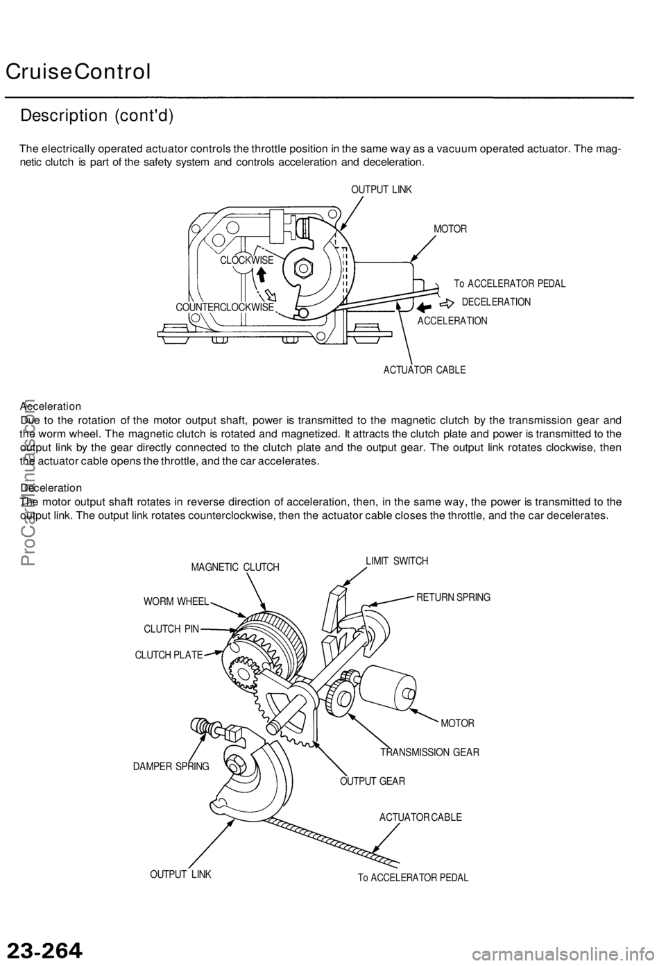
The electrically operated actuator controls the throttle position in the same way as a vacuum operated actuator. The mag-
netic clutch is part of the safety system and controls acceleration and deceleration.
OUTPUT LINK
MOTOR
To ACCELERATOR PEDAL
DECELERATION
ACCELERATION
ACTUATOR CABLE
Acceleration
Due to the rotation of the motor output shaft, power is transmitted to the magnetic clutch by the transmission gear and
the worm wheel. The magnetic clutch is rotated and magnetized. It attracts the clutch plate and power is transmitted to the
output link by the gear directly connected to the clutch plate and the output gear. The output link rotates clockwise, then
the actuator cable opens the throttle, and the car accelerates.
Deceleration
The motor output shaft rotates in reverse direction of acceleration, then, in the same way, the power is transmitted to the
output link. The output link rotates counterclockwise, then the actuator cable closes the throttle, and the car decelerates.
MAGNETIC CLUTCH
LIMIT SWITCH
WORM WHEEL
CLUTCH PIN
CLUTCH PLATE
DAMPER SPRING
RETURN SPRING
OUTPUT LINK
MOTOR
TRANSMISSION GEAR
OUTPUT GEAR
ACTUATOR CABLE
To ACCELERATOR PEDAL
COUNTERCLOCKWISE
CLOCKWISEProCarManuals.com
Page 1725 of 1771

Actuator Assembl y Tes t
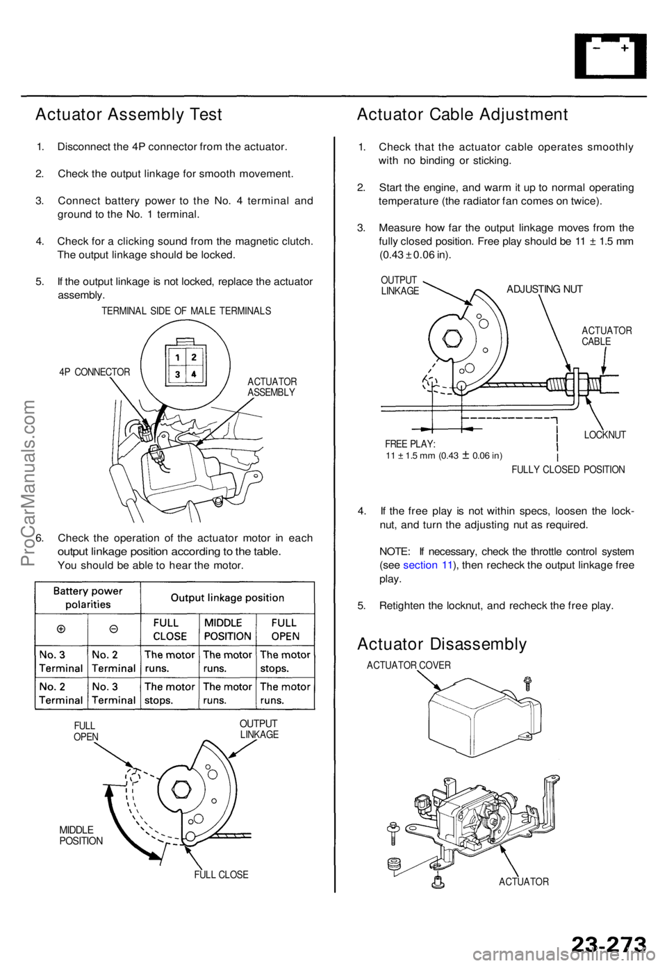
1. Disconnec t th e 4 P connecto r fro m th e actuator .
2 . Chec k th e outpu t linkag e fo r smoot h movement .
3 . Connec t batter y powe r t o th e No . 4 termina l an d
groun d t o th e No . 1 terminal .
4 . Chec k fo r a clickin g soun d fro m th e magneti c clutch .
Th e outpu t linkag e shoul d b e locked .
5 . I f th e outpu t linkag e is no t locked , replac e th e actuato r
assembly .
TERMINA L SID E O F MAL E TERMINAL S
4 P CONNECTO R
ACTUATOR
ASSEMBL Y
6. Chec k th e operatio n o f th e actuato r moto r i n eac h
outpu t linkag e positio n accordin g to th e table .
You shoul d b e abl e t o hea r th e motor .
OUTPU TLINKAG E
MIDDLEPOSITIO N
FULL CLOS E
Actuato r Cabl e Adjustmen t
1. Chec k tha t th e actuato r cabl e operate s smoothl y
wit h n o bindin g o r sticking .
2 . Star t th e engine , an d war m it u p to norma l operatin g
temperatur e (th e radiato r fa n come s o n twice) .
3 . Measur e ho w fa r th e outpu t linkag e move s fro m th e
full y close d position . Fre e pla y shoul d b e 1 1 ± 1. 5 m m
(0.4 3 ± 0.0 6 in) .
OUTPU T
LINKAG EADJUSTIN G NU T
ACTUATO RCABLE
4. I f th e fre e pla y i s no t withi n specs , loose n th e lock -
nut , an d tur n th e adjustin g nu t a s required .
NOTE : I f necessary , chec k th e throttl e contro l syste m
(se e sectio n 11 ), the n rechec k th e outpu t linkag e fre e
play .
5. Retighte n th e locknut , an d rechec k th e fre e play .
Actuato r Disassembl y
ACTUATOR COVE R
ACTUATO R
FULL
OPE N FULL
Y CLOSE D POSITIO N
LOCKNU
T
FRE E PLAY :
11 ± 1. 5 m m (0.4 3 ± 0.06 in)
ProCarManuals.com