Page 942 of 1771
Position
Hydraulic pressure is not applied to the clutches. Power is not transmitted to the countershaft.
Position
Hydraulic pressure is not applied to the clutches. Power is not transmitted to the countershaft. The countershaft is locked
by the parking brake pawl interlocking the parking gear.
TORQUE
CONVERTER
SECONDARY
DRIVE
GEAR
2ND CLUTCH
4TH CLUTCH
1ST CLUTCH
MAINSHAFT
COUNTERSHAFT
1ST-HOLD
CLUTCH
ONE-WAY CLUTCH
SERVO VALVE
(SHIFT FORK SHAFT)
3RD CLUTCH
SECONDARY DRIVEN
GEARProCarManuals.com
Page 971 of 1771
Description
The parking brake mechanism locks the transmission by engaging the parking brake pawl into the parking gear which is
splined to the countershaft.
Shifting to position causes the parking brake pawl roller (installed at the end of the parking brake shift arm) to press the
parking brake pawl onto the parking gear. Even if the end of the parking brake pawl rides on top of the parking gear teeth,
slight movement of the countershaft will cause the parking brake pawl and the parking gear to mesh with each other com-
pletely, because the parking brake shift arm receives tension from the parking brake shift arm spring. The parking brake
pawl receives the tension (which acts to separate the parking brake pawl from the parking gear) from the parking pawl
spring.
PARKING GEAR
COUNTERSHAFT
1ST GEAR
PARKING BRAKE
PAWL
PARKING BRAKE
PAWL ROLLER
CONTROL SHAFT
PARKING PAWL
SPRING
PARKING BRAKE
SHIFT ARM
Parking Brake MechanismProCarManuals.com
Page 994 of 1771
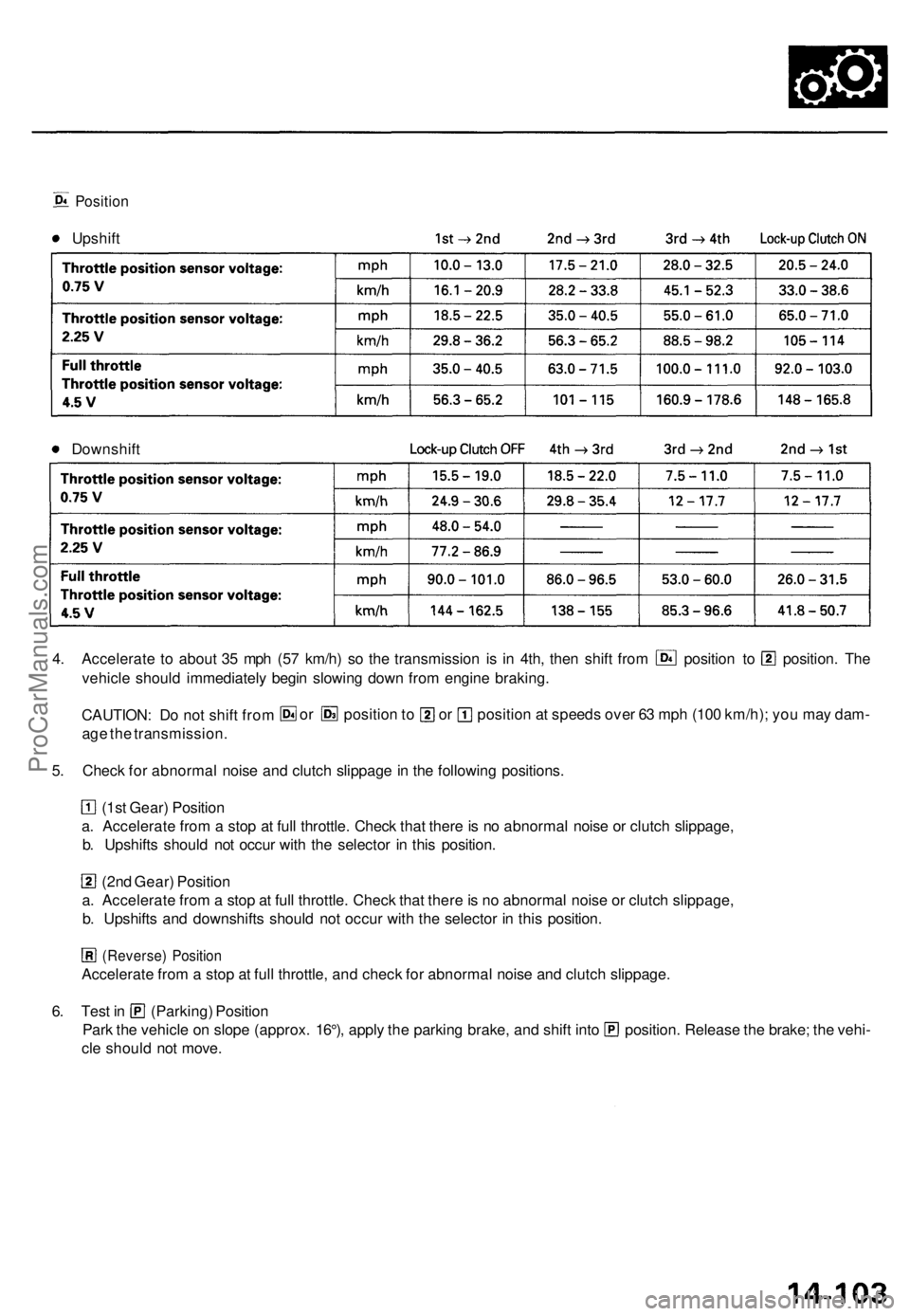
Position
Upshift
Downshift
4. Accelerate to about 35 mph (57 km/h) so the transmission is in 4th, then shift from position to position. The
vehicle should immediately begin slowing down from engine braking.
CAUTION: Do not shift from
age the transmission.
or position to or position at speeds over 63 mph (100 km/h); you may dam-
5. Check for abnormal noise and clutch slippage in the following positions.
(1st Gear) Position
a. Accelerate from a stop at full throttle. Check that there is no abnormal noise or clutch slippage,
b. Upshifts should not occur with the selector in this position.
(2nd Gear) Position
a. Accelerate from a stop at full throttle. Check that there is no abnormal noise or clutch slippage,
b. Upshifts and downshifts should not occur with the selector in this position.
(Reverse) Position
Accelerate from a stop at full throttle, and check for abnormal noise and clutch slippage.
6. Test in (Parking) Position
Park the vehicle on slope (approx. 16°), apply the parking brake, and shift into position. Release the brake; the vehi-
cle should not move.ProCarManuals.com
Page 1066 of 1771
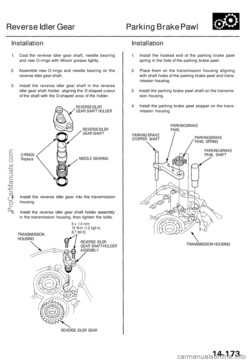
Reverse Idler Gear
Parking Brake Pawl
Installation
1. Coat the reverse idler gear shaft, needle bearing
and new O-rings with lithium grease lightly.
2. Assemble new O-rings and needle bearing on the
reverse idler gear shaft.
3. Install the reverse idler gear shaft in the reverse
idler gear shaft holder, aligning the D-shaped cutout
of the shaft with the D-shaped area of the holder.
REVERSE IDLER
GEAR SHAFT HOLDER
REVERSE IDLER
GEAR SHAFT
O-RINGS
Replace.
NEEDLE BEARING
4. Install the reverse idler gear into the transmission
housing.
5. Install the reverse idler gear shaft holder assembly
in the transmission housing, then tighten the bolts.
TRANSMISSION
HOUSING
6 x 1.0 mm
12 N-m (1.2 kgf-m,
8.7 Ibf-ft)
REVERSE IDLER
GEAR SHAFT/HOLDER
ASSEMBLY
REVERSE IDLER GEAR
Installation
1. Install the hooked end of the parking brake pawl
spring in the hole of the parking brake pawl.
2. Place them on the transmission housing aligning
with shaft holes of the parking brake pawl and trans-
mission housing.
3. Install the parking brake pawl shaft on the transmis-
sion housing.
4. Install the parking brake pawl stopper on the trans-
mission housing.
PARKING BRAKE
PAWL
PARKING BRAKE
STOPPER SHAFT
PARKING BRAKE
PAWL SPRING
PARKING BRAKE
PAWL SHAFT
TRANSMISSION HOUSINGProCarManuals.com
Page 1067 of 1771
Parking Brake Roller Rod
Adjustment
1. Move the detent lever to the position.
2. Measure the clearance between the parking brake
roller rod and the transmission housing as shown.
STANDARD: 3.8 - 4.3 mm (0.15 - 0.17 in)
Measuring Clearance
ROLLER
TRANSMISSION
HOUSING
DETENT LEVER
ROLLER ROD
3. If the clearance is out of tolerance, select and install
a new parking brake roller rod.
PARKING BRAKE ROLLER ROD
Mark
L Length
PARKING BRAKE ROLLER ROD
Mark
1 or None
2
0
3
Part Number
24550 -PW4- 010
24560 -PW4- 010
24580 -PW4- 010
24590 - PW4 - 000
Length "L"
36.0 mm (1.417 in)
35.6 mm (1.402 in)
36.4 mm (1.433 in)
36.2 mm (1.425 in)
4. After replacing the parking brake roller rod, make
sure that the clearance is within tolerance.ProCarManuals.com
Page 1068 of 1771
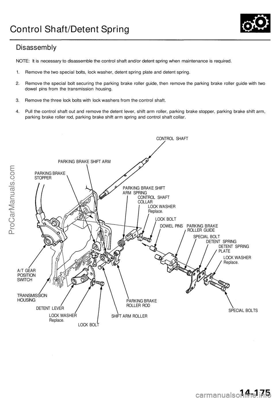
Control Shaft/Detent Spring
Disassembly
NOTE: It is necessary to disassemble the control shaft and/or detent spring when maintenance is required.
1. Remove the two special bolts, lock washer, detent spring plate and detent spring.
2. Remove the special bolt securing the parking brake roller guide, then remove the parking brake roller guide with two
dowel pins from the transmission housing.
3. Remove the three lock bolts with lock washers from the control shaft.
4. Pull the control shaft out and remove the detent lever, shift arm roller, parking brake stopper, parking brake shift arm,
parking brake roller rod, parking brake shift arm spring and control shaft collar.
CONTROL SHAFT
PARKING BRAKE SHIFT ARM
PARKING BRAKE
STOPPER
DOWEL PINS PARKING BRAKE
ROLLER GUIDE
A/T GEAR
POSITION
SWITCH
TRANSMISSION
HOUSING
DETENT LEVER
LOCK WASHER
Replace.
SHIFT ARM ROLLER
SPECIAL BOLT
DETENT SPRING
DETENT SPRING
PLATE
LOCK WASHER
Replace.
SPECIAL BOLTS
LOCK BOLT
PARKING BRAKE
ROLLER ROD
LOCK BOLT
LOCK WASHER
Replace.
CONTROL SHAFT
COLLAR
PARKING BRAKE SHIFT
ARM SPRINGProCarManuals.com
Page 1077 of 1771
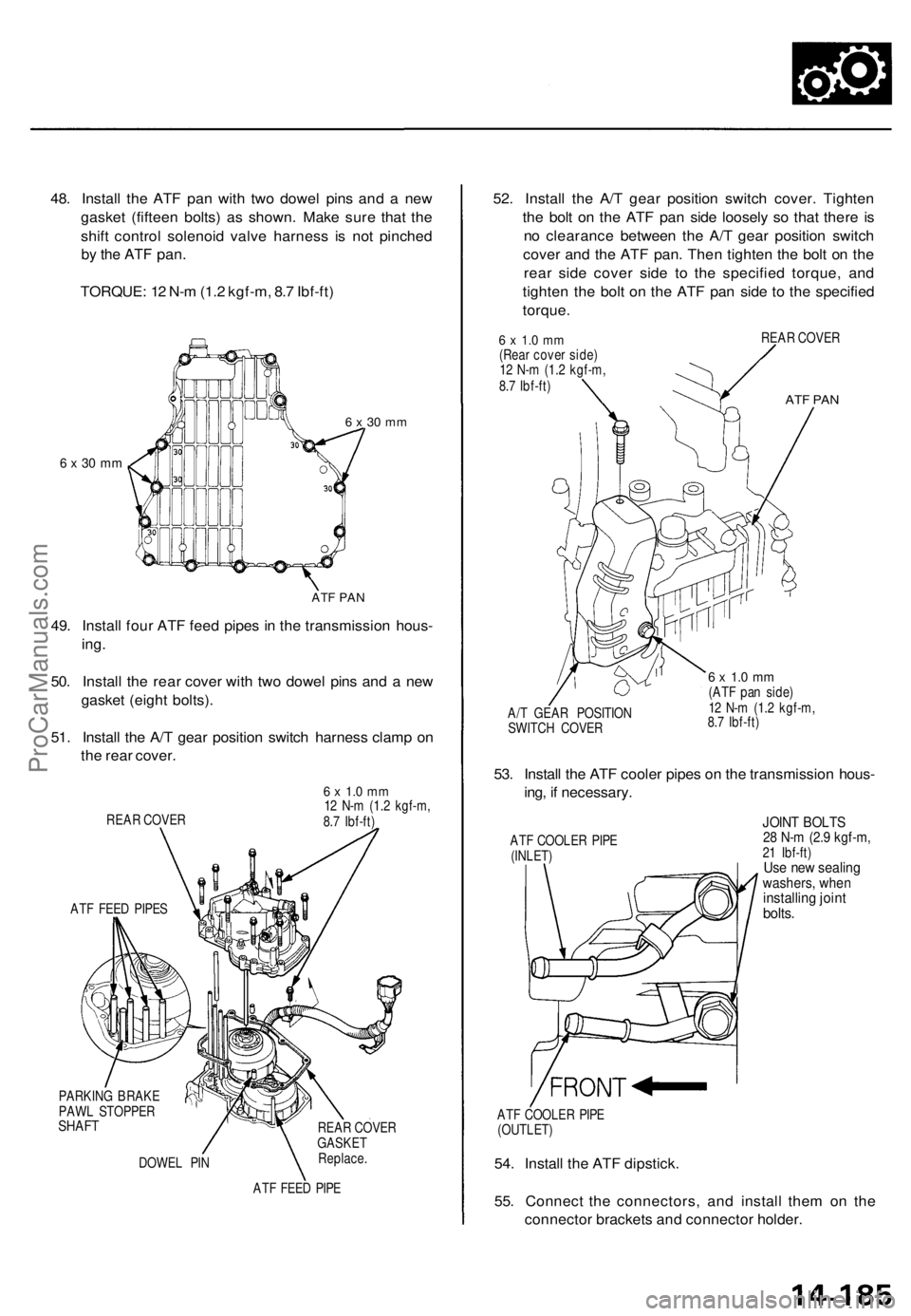
48. Install the ATF pan with two dowel pins and a new
gasket (fifteen bolts) as shown. Make sure that the
shift control solenoid valve harness is not pinched
by the ATF
pan.
TORQUE: 12 N-m (1.2 kgf-m, 8.7 Ibf-ft)
6 x 30 mm
6 x 30 mm
ATF PAN
49. Install four ATF feed pipes in the transmission hous-
ing.
50. Install the rear cover with two dowel pins and a new
gasket (eight bolts).
51. Install the A/T gear position switch harness clamp on
the rear cover.
REAR COVER
ATF FEED PIPES
6 x 1.0 mm
12 N-m (1.2 kgf-m,
8.7 Ibf-ft)
PARKING BRAKE
PAWL STOPPER
SHAFT
DOWEL PIN
REAR COVER
GASKET
Replace.
ATF FEED PIPE
52. Install the A/T gear position switch cover. Tighten
the bolt on the ATF pan side loosely so that there is
no clearance between the A/T gear position switch
cover and the ATF pan. Then tighten the bolt on the
rear side cover side to the specified torque, and
tighten the bolt on the ATF pan side to the specified
torque.
6 x 1.0 mm
(Rear cover side)
12 N-m (1.2 kgf-m,
8.7 Ibf-ft)
REAR COVER
ATF PAN
A/T GEAR POSITION
SWITCH COVER
6 x 1.0 mm
(ATF pan side)
12 N-m (1.2 kgf-m,
8.7 Ibf-ft)
53. Install the ATF cooler pipes on the transmission hous-
ing, if necessary.
ATF COOLER PIPE
(INLET)
JOINT BOLTS
28 N-m (2.9 kgf-m,
21 Ibf-ft)
Use new sealing
washers, when
installing joint
bolts.
ATF COOLER PIPE
(OUTLET)
54. Install the ATF dipstick.
55. Connect the connectors, and install them on the
connector brackets and connector holder.ProCarManuals.com
Page 1252 of 1771
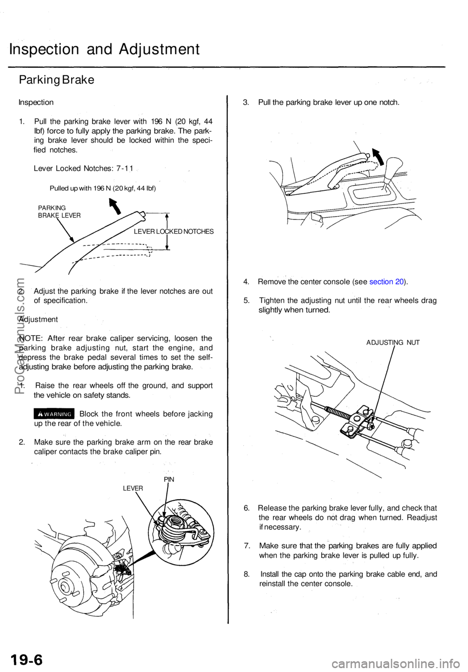
Inspection an d Adjustmen t
Parking Brak e
Inspectio n
1. Pul l th e parkin g brak e leve r wit h 19 6 N (2 0 kgf , 4 4
Ibf) forc e to full y appl y th e parkin g brake . Th e park -
ing brak e leve r shoul d b e locke d withi n th e speci -
fie d notches .
Leve r Locke d Notches : 7-1 1
Pulle d u p wit h 19 6 N (2 0 kgf , 4 4 Ibf )
PARKIN GBRAKE LEVE R
LEVER LOCKE D NOTCHE S
2.Adjus t th e parkin g brak e i f th e leve r notche s ar e ou t
o f specification .
Adjustmen t
NOTE: Afte r rea r brak e calipe r servicing , loose n th e
parkin g brak e adjustin g nut , star t th e engine , an d
depres s th e brak e peda l severa l time s t o se t th e self -
adjustin g brak e befor e adjustin g th e parkin g brake .
1. Rais e th e rea r wheel s of f th e ground , an d suppor t
the vehicl e o n safet y stands .
Block th e fron t wheel s befor e jackin g
u p th e rea r o f th e vehicle .
2 . Mak e sur e th e parkin g brak e ar m o n th e rea r brak e
calipe r contact s th e brak e calipe r pin .
PIN
LEVE R
3. Pul l th e parkin g brak e leve r u p on e notch .
4. Remov e th e cente r consol e (se e sectio n 20 ).
5 . Tighte n th e adjustin g nu t unti l th e rea r wheel s dra g
slightl y whe n turned .
ADJUSTIN G NU T
6. Releas e th e parkin g brak e leve r fully , an d chec k tha t
th e rea r wheel s d o no t dra g whe n turned . Readjus t
i f necessary .
7. Mak e sur e tha t th e parkin g brake s ar e full y applie d
when th e parkin g brak e leve r i s pulle d u p fully .
8 . Instal l th e ca p ont o th e parkin g brak e cabl e end , an d
reinstal l th e cente r console .
ProCarManuals.com