1995 ACURA TL parking brake
[x] Cancel search: parking brakePage 1267 of 1771
Rear Brake Pads
Inspection and Replacement
• Never use an air hose or dry brush to clean brake
assemblies.
• Use an OSHA-approved vacuum cleaner to avoid
breathing brake dust.
1. Block the front wheels, loosen the rear wheel nuts
slightly, support the rear of vehicle on safety
stands, then remove the rear wheels.
2. Release the parking brake.
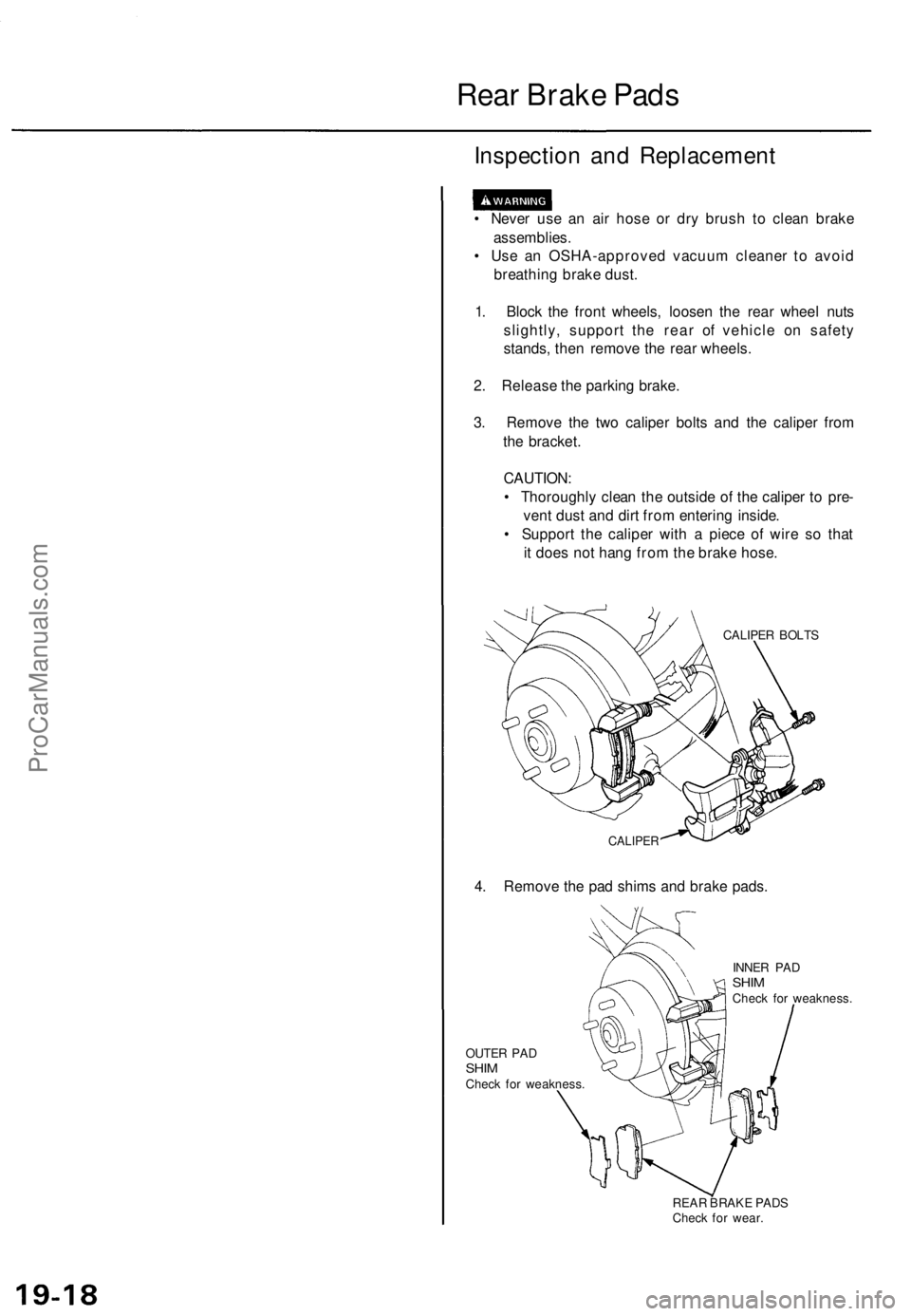
3. Remove the two caliper bolts and the caliper from
the bracket.
CAUTION:
• Thoroughly clean the outside of the caliper to pre-
vent dust and dirt from entering inside.
• Support the caliper with a piece of wire so that
it does not hang from the brake hose.
CALIPER BOLTS
CALIPER
4. Remove the pad shims and brake pads.
OUTER PAD
SHIM
Check for weakness.
INNER PAD
SHIM
Check for weakness.
REAR BRAKE PADS
Check for wear.ProCarManuals.com
Page 1272 of 1771
Rear Brake Caliper
Disassembly
• Never use an air hose or dry brush to clean brake
assemblies.
• Use an OSHA-approved vacuum cleaner to avoid
breathing brake dust.
• Contaminated brake discs or pads reduce stopping
ability.
CAUTION:
• Do not spill brake fluid on the vehicle; it may damage
the paint; if brake fluid does contact the paint, wash
it off immediately with water.
• To prevent spills, cover the hose joints with rags or
shop towels.
• Clean all parts in brake fluid and air dry; blow out all
passages with compressed air.
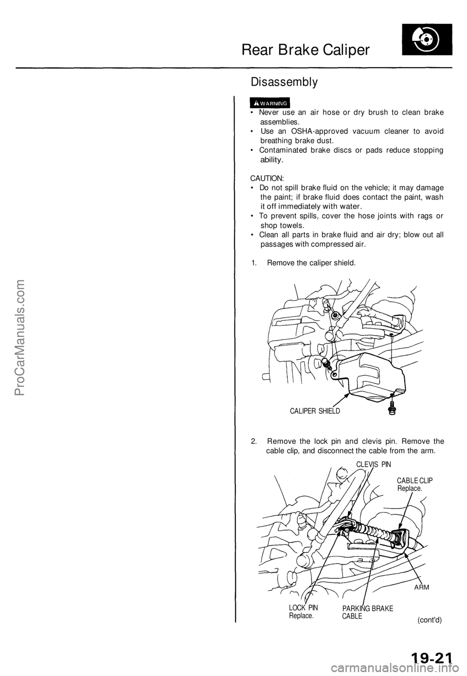
1. Remove the caliper shield.
CALIPER SHIELD
2. Remove the lock pin and clevis pin. Remove the
cable clip, and disconnect the cable from the arm.
CLEVIS PIN
CABLE CLIP
Replace.
LOCK PIN
Replace.
PARKING BRAKE
CABLE
ARM
(cont'd)ProCarManuals.com
Page 1275 of 1771
Rear Brake Caliper
Disassembly (cont'd)
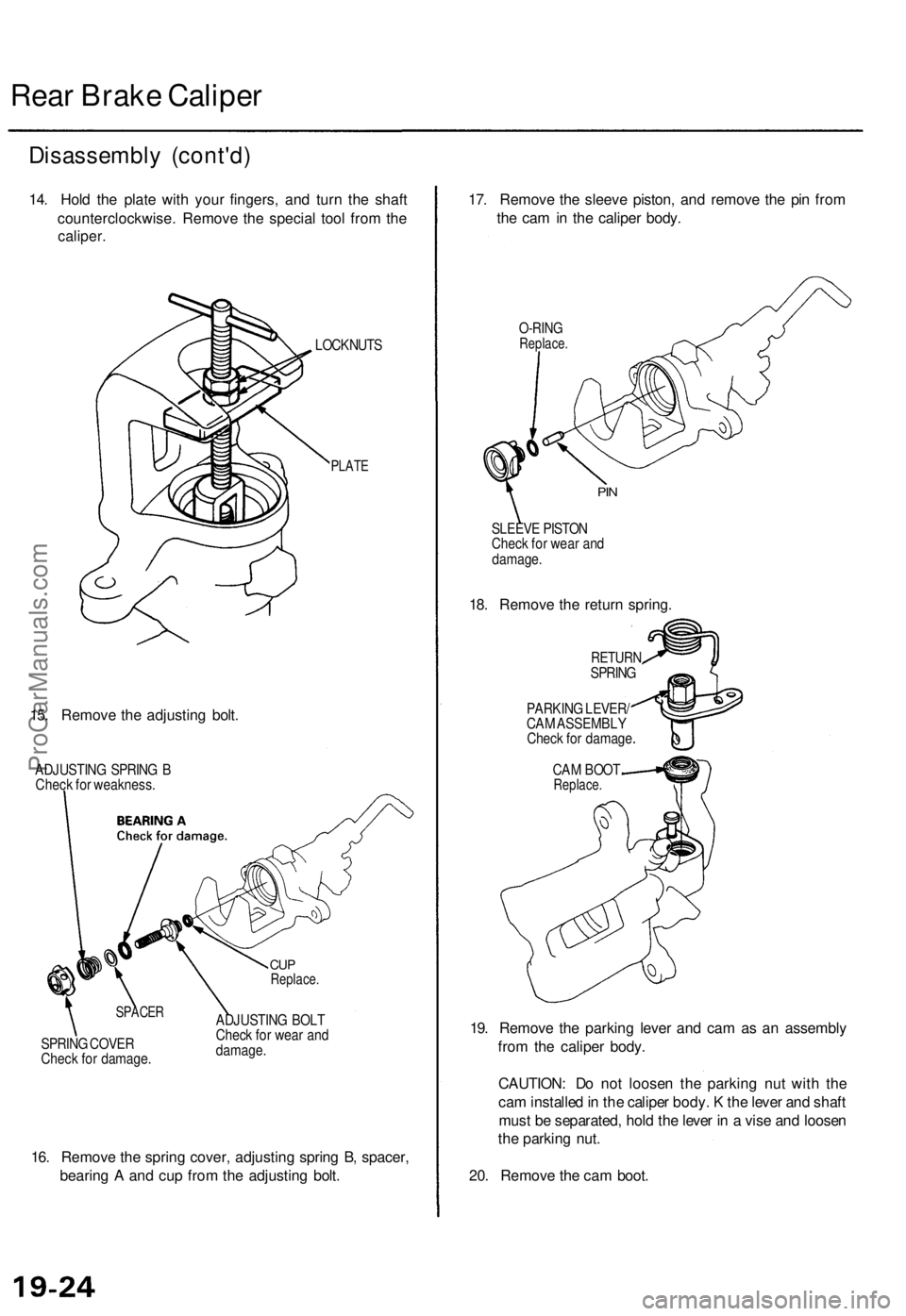
14. Hold the plate with your fingers, and turn the shaft
counterclockwise. Remove the special tool from the
caliper.
LOCKNUTS
PLATE
15. Remove the adjusting bolt.
ADJUSTING SPRING B
Check for weakness.
SPACER
SPRING COVER
Check for damage.
CUP
Replace.
ADJUSTING BOLT
Check for wear and
damage.
16. Remove the spring cover, adjusting spring B, spacer,
bearing A and cup from the adjusting bolt.
17. Remove the sleeve piston, and remove the pin from
the cam in the caliper body.
O-RING
Replace.
PIN
SLEEVE PISTON
Check for wear and
damage.
18. Remove the return spring.
RETURN
SPRING
PARKING LEVER/
CAM ASSEMBLY
Check for damage
CAM BOOT
Replace.
19. Remove the parking lever and cam as an assembly
from the caliper body.
CAUTION: Do not loosen the parking nut with the
cam installed in the caliper body. K the lever and shaft
must be separated, hold the lever in a vise and loosen
the parking nut.
20. Remove the cam boot.ProCarManuals.com
Page 1276 of 1771
Reassembly
Never use an air hose or dry brush to clean brake assemblies.
Use an OSHA-approved vacuum cleaner to avoid breathing brake dust.
Contaminated brake discs or pads reduce stopping ability.
When reusing the pads. Install them in their original positions to prevent loss of braking efficiency.
CAUTION:
Do not spill brake fluid on the vehicle; It may damage the paint; if brake fluid does contact the paint, wash it off imme-
diately with water.
Clean all parts in brake fluid and air dry; blow out all passages with compressed air.
Before reassembling, check that all parts are free of dust and other foreign particles.
Replace parts with new ones whenever specified to do so.
Make sure no dirt or other foreign matter is allowed to contaminate the brake fluid.
Always use Genuine Honda DOT 3 Brake Fluid. Using a non-Honda brake fluid can cause corrosion and decrease the
life of the system.
NOTE:
Coat piston, piston seal groove, and caliper bore with clean brake fluid.
Replace all rubber parts with new ones whenever disassembled.
: Use recommended silicone greases in the caliper seal set.
: Use recommended rubber grease in the caliper seal set.
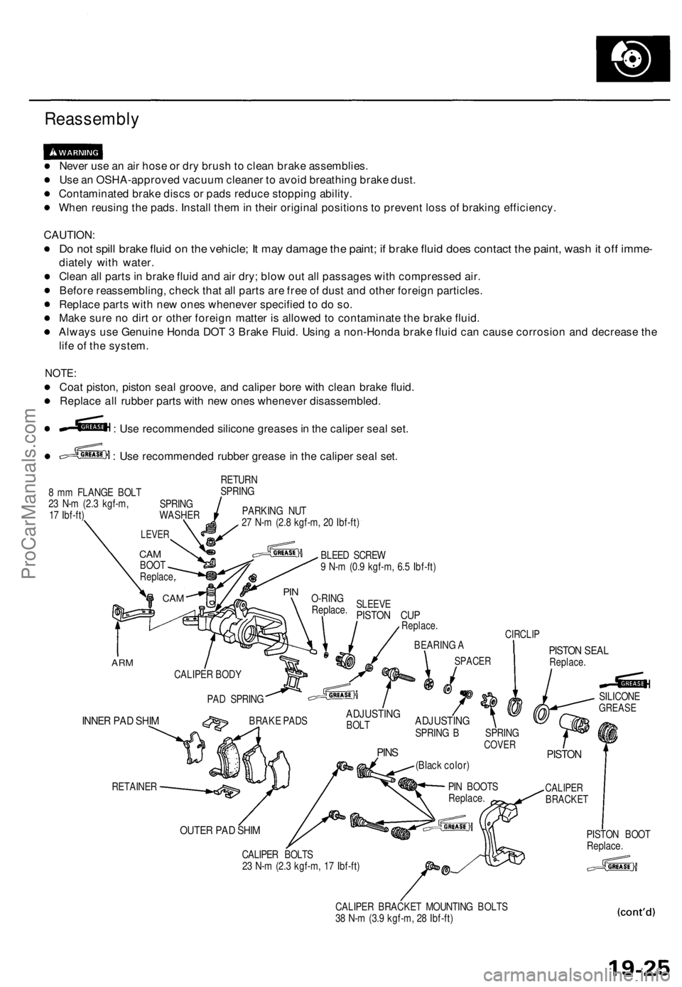
8 mm FLANGE BOLT
23 N-m (2.3 kgf-m,
17 Ibf-ft)
RETURN
SPRING
PARKING NUT
27 N-m (2.8 kgf-m, 20 Ibf-ft)
BLEED SCREW
9 N-m (0.9 kgf-m, 6.5 Ibf-ft)
SLEEVE
PISTON CUP
Replace.
ARM
INNER PAD SHIM
RETAINER
CALIPER BODY
PAD SPRING
CIRCLIP
BEARING A
SPACER
PISTON SEAL
Replace.
BRAKE PADS
ADJUSTING
BOLT
PINS
ADJUSTING
SPRING B SPRING
COVER
(Black color)
PISTON
CALIPER
BRACKET
OUTER PAD SHIM
CALIPER BOLTS
23 N-m (2.3 kgf-m, 17 Ibf-ft)
CALIPER BRACKET MOUNTING BOLTS
38 N-m (3.9 kgf-m, 28 Ibf-ft)
PISTON BOOT
Replace.
SILICONE
GREASE
O-RING
Replace.
PIN
CAM
LEVER
CAM
BOOT
Replace,
SPRING
WASHER
PIN BOOTS
Replace.ProCarManuals.com
Page 1277 of 1771
Rear Brake Caliper
Reassembly (cont'd)
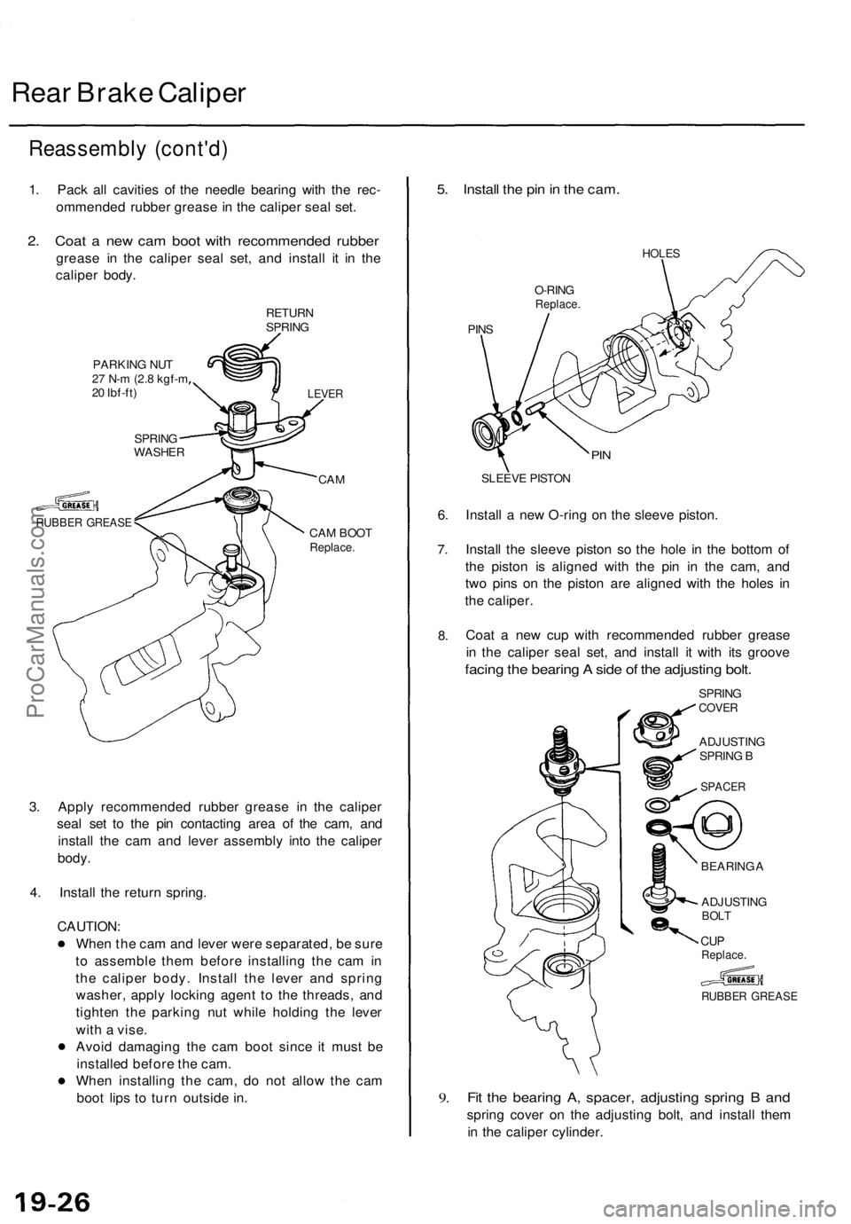
1. Pack all cavities of the needle bearing with the rec-
ommended rubber grease in the caliper seal set.
2. Coat a new cam boot with recommended rubber
grease in the caliper seal set, and install it in the
caliper body.
RETURN
SPRING
PARKING NUT
27 N-m (2.8 kgf-m
20 Ibf-ft)
SPRING
WASHER
RUBBER GREASE
LEVER
CAM
CAM BOOT
Replace.
3. Apply recommended rubber grease in the caliper
seal set to the pin contacting area of the cam, and
install the cam and lever assembly into the caliper
body.
4. Install the return spring.
CAUTION:
When the cam and lever were separated, be sure
to assemble them before installing the cam in
the caliper body. Install the lever and spring
washer, apply locking agent to the threads, and
tighten the parking nut while holding the lever
with a vise.
Avoid damaging the cam boot since it must be
installed before the cam.
When installing the cam, do not allow the cam
boot lips to turn outside in.
5. Install the pin in the cam.
HOLES
O-RING
Replace.
PINS
PIN
SLEEVE PISTON
6. Install a new O-ring on the sleeve piston.
7.
8.
Install the sleeve piston so the hole in the bottom of
the piston is aligned with the pin in the cam, and
two pins on the piston are aligned with the holes in
the caliper.
Coat a new cup with recommended rubber grease
in the caliper seal set, and install it with its groove
facing the bearing A side of the adjusting bolt.
SPRING
COVER
ADJUSTING
SPRING B
RUBBER GREASE
9.
Fit the bearing A, spacer, adjusting spring B and
spring cover on the adjusting bolt, and install them
in the caliper cylinder.
BEARING A
ADJUSTING
BOLT
CUP
Replace.
SPACERProCarManuals.com
Page 1283 of 1771
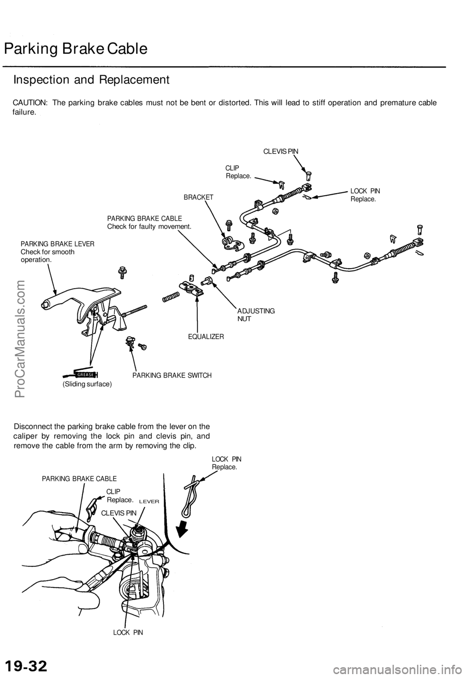
Parking Brake Cable
Inspection and Replacement
CAUTION: The parking brake cables must not be bent or distorted. This will lead to stiff operation and premature cable
failure.
CLEVIS PIN
CLIP
Replace.
BRACKET
PARKING BRAKE CABLE
Check for faulty movement.
PARKING BRAKE LEVER
Check for smooth
operation.
PARKING BRAKE SWITCH
(Sliding surface)
Disconnect the parking brake cable from the lever on the
caliper by removing the lock pin and clevis pin, and
remove the cable from the arm by removing the clip.
PARKING BRAKE CABLE
CLIP
Replace.
LEVER
CLEVIS PIN
LOCK PIN
Replace.
LOCK PIN
LOCK PIN
Replace.
ADJUSTING
NUT
EQUALIZERProCarManuals.com
Page 1290 of 1771
Anti-lock Brake System (ABS)
Features/Construction (cont'd)
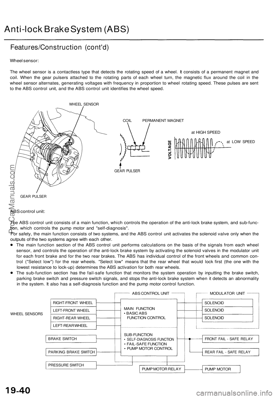
Wheel sensor:
The wheel sensor is a contactless type that detects the rotating speed of a wheel. It consists of a permanent magnet and
coil. When the gear pulsers attached to the rotating parts of each wheel turn, the magnetic flux around the coil in the
wheel sensor alternates, generating voltages with frequency in proportion to wheel rotating speed. These pulses are sent
to the ABS control unit, and the ABS control unit identifies the wheel speed.
WHEEL SENSOR
COIL PERMANENT MAGNET
at HIGH SPEED
at LOW SPEED
GEAR PULSER
GEAR PULSER
ABS control unit:
The ABS control unit consists of a main function, which controls the operation of the anti-lock brake system, and sub-func-
tion, which controls the pump motor and "self-diagnosis".
For safety, the main function consists of two systems, and the ABS control unit activates the solenoid valve only when the
outputs of the two systems agree with each other.
The main function section of the ABS control unit performs calculations on the basis of the signals from each wheel
sensor, and controls the operation of the anti-lock brake system by activating the solenoid valves in the modulator unit
for each front brake and for the two rear brakes. The ABS has individual control of the front wheels and common con-
trol ("Select low") for the rear wheels. "Select low" means that the rear wheel that would lock first (the one with the
lowest resistance to lock-up) determines the ABS activation for both rear wheels.
The sub-function section has the fail-safe function that monitors the system operation by inputting the brake switch,
parking brake switch and pressure switch signals, and stops the anti-lock brake system when it detects an abnormality
in the system. It also has a self-diagnosis function and the pump motor control function.
WHEEL SENSORS
ABS CONTROL UNIT
RIGHT-FRONT WHEEL
LEFT-FRONT WHEEL
RIGHT-REAR WHEEL
LEFT-REAR WHEEL
BRAKE SWITCH
PARKING BRAKE SWITCH
MAIN FUNCTION
• BASIC ABS
FUNCTION CONTROL
SUB-FUNCTION
• SELF-DIAGNOSIS FUNCTION
• FAIL-SAFE FUNCTION
• PUMP MOTOR CONTROL
PRESSURE SWITCH
PUMP MOTOR RELAY
MODULATOR UNIT
SOLENOID
SOLENOID
SOLENOID
FRONT FAIL - SAFE RELAY
REAR FAIL - SAFE RELAY
PUMP MOTORProCarManuals.com
Page 1291 of 1771
Pump motor control:
The ABS control unit monitors the brake fluid pressure in the accumulator by the pressure switch ON/OFF signals. The
ABS control unit turns the pump on when the pressure in the accumulator drops, and stops the pump when the pressure
rises to the specified value.
If the pressure does not reach the specified value after the motor has operated continuously for a specified period, the
ABS control unit stops the motor and activates the ABS indicator light.
Self-diagnosis function:
The self-diagnosis function, provided in the sub-function of the ABS control unit, monitors the main system functions by
constantly transmitting the data between the two Central Processing Units (CPUs). When an abnormality is detected, the
ABS control unit turns the ABS indicator light on and stops the ABS, although the basic brake system continues to operate
normally.
When the ABS control unit detects an abnormality with the ABS and turns the ABS indicator light on, the diagnostic trou-
ble code (DTC), which shows the problem part or unit, is recorded in the control unit. The DTC can be read by the blinking
frequency of the ABS indicator light.
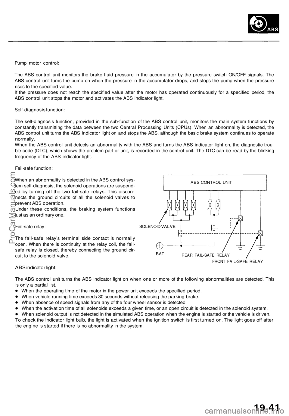
Fail-safe function:
When an abnormality is detected in the ABS control sys-
tem self-diagnosis, the solenoid operations are suspend-
ed by turning off the two fail-safe relays. This discon-
nects the ground circuits of all the solenoid valves to
prevent ABS operation.
Under these conditions, the braking system functions
just as an ordinary one.
Fail-safe relay:
The fail-safe relay's terminal side contact is normally
open. When there is continuity at the relay coil, the fail-
safe relay is closed, thereby connecting the ground cir-
cuit to the solenoid valve.
ABS indicator light:
SOLENOID VALVE
BAT
REAR FAIL-SAFE RELAY
FRONT FAIL-SAFE RELAY
The ABS control unit turns the ABS indicator light on when one or more of the following abnormalities are detected. This
is only a partial list.
When the operating time of the motor in the power unit exceeds the specified period.
When vehicle running time exceeds 30 seconds without releasing the parking brake.
When absence of speed signals from any of the four wheel sensor is detected.
When the activation time of all solenoids exceeds a given time, or an open circuit is detected in the solenoid system.
When solenoid output is not detected in the simulated ABS operation when the engine is started or the vehicle is driven.
To check the indicator light bulb, the light is activated when the ignition switch is first turned on. The light goes off after
the engine is started if there is no abnormality in the system.
ABS CONTROL UNITProCarManuals.com