1994 JEEP CHEROKEE suspension
[x] Cancel search: suspensionPage 1029 of 1784
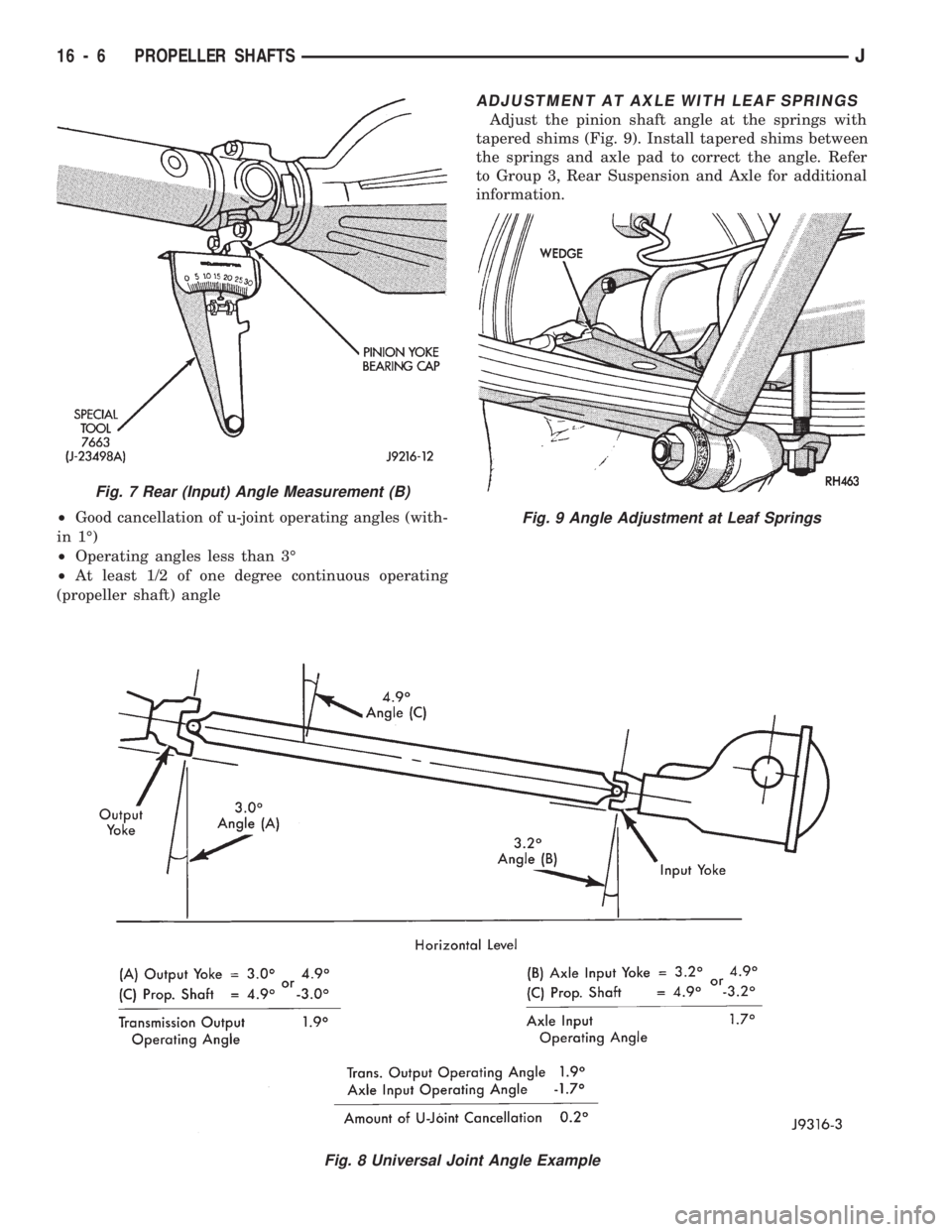
²Good cancellation of u-joint operating angles (with-
in 1É)
²Operating angles less than 3É
²At least 1/2 of one degree continuous operating
(propeller shaft) angle
ADJUSTMENT AT AXLE WITH LEAF SPRINGS
Adjust the pinion shaft angle at the springs with
tapered shims (Fig. 9). Install tapered shims between
the springs and axle pad to correct the angle. Refer
to Group 3, Rear Suspension and Axle for additional
information.
Fig. 8 Universal Joint Angle Example
Fig. 7 Rear (Input) Angle Measurement (B)
Fig. 9 Angle Adjustment at Leaf Springs
16 - 6 PROPELLER SHAFTSJ
Page 1051 of 1784
STEERING LINKAGEÐXJ
INDEX
page page
Drag Link.............................. 14
Pitman Arm............................. 15
Service Information....................... 14Steering Dampener....................... 15
Tie Rod ................................ 14
SERVICE INFORMATION
The steering linkage consists of a pitman arm, drag
link, tie rod, and steering dampener. Adjustment
sleeves are used on the tie rod and drag link for toe
and steering wheel alignment.
Refer to Group 2, Front Suspension and Axle for
additional information.
The tie-rod end ball stud seals should be inspected
during all oil changes.
A damaged ball stud seal requires removal of the
seal. Inspect the tie-rod end ball stud at the throat
opening. Check for lubricant loss, contamination, ball
stud wear or corrosion. If these conditions exist, re-
place the tie-rod. A replacement seal can be installed
if lubricant is in good condition. Otherwise, a com-
plete replacement ball stud end should be installed.
Lubricate the tie-rod end with MOPARtMulti-Mile-
age Lubricant, or equivalent product.
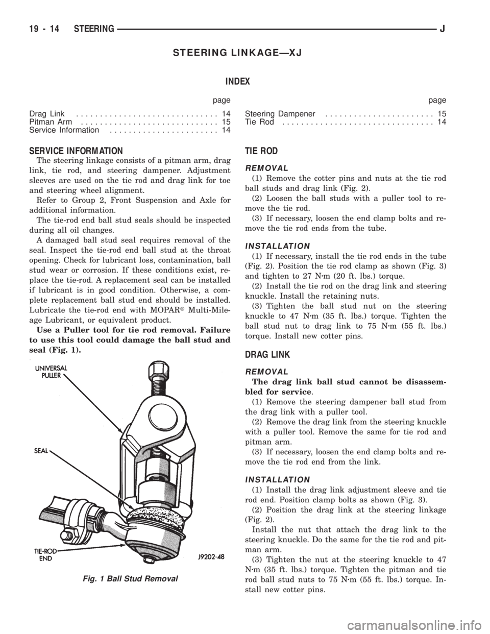
Use a Puller tool for tie rod removal. Failure
to use this tool could damage the ball stud and
seal (Fig. 1).
TIE ROD
REMOVAL
(1) Remove the cotter pins and nuts at the tie rod
ball studs and drag link (Fig. 2).
(2) Loosen the ball studs with a puller tool to re-
move the tie rod.
(3) If necessary, loosen the end clamp bolts and re-
move the tie rod ends from the tube.
INSTALLATION
(1) If necessary, install the tie rod ends in the tube
(Fig. 2). Position the tie rod clamp as shown (Fig. 3)
and tighten to 27 Nzm (20 ft. lbs.) torque.
(2) Install the tie rod on the drag link and steering
knuckle. Install the retaining nuts.
(3) Tighten the ball stud nut on the steering
knuckle to 47 Nzm (35 ft. lbs.) torque. Tighten the
ball stud nut to drag link to 75 Nzm (55 ft. lbs.)
torque. Install new cotter pins.
DRAG LINK
REMOVAL
The drag link ball stud cannot be disassem-
bled for service.
(1) Remove the steering dampener ball stud from
the drag link with a puller tool.
(2) Remove the drag link from the steering knuckle
with a puller tool. Remove the same for tie rod and
pitman arm.
(3) If necessary, loosen the end clamp bolts and re-
move the tie rod end from the link.
INSTALLATION
(1) Install the drag link adjustment sleeve and tie
rod end. Position clamp bolts as shown (Fig. 3).
(2) Position the drag link at the steering linkage
(Fig. 2).
Install the nut that attach the drag link to the
steering knuckle. Do the same for the tie rod and pit-
man arm.
(3) Tighten the nut at the steering knuckle to 47
Nzm (35 ft. lbs.) torque. Tighten the pitman and tie
rod ball stud nuts to 75 Nzm (55 ft. lbs.) torque. In-
stall new cotter pins.
Fig. 1 Ball Stud Removal
19 - 14 STEERINGJ
Page 1054 of 1784
STEERING LINKAGEÐYJ
INDEX
page page
Drag Link.............................. 17
Pitman Arm............................. 18
Service Information....................... 17Steering Dampener....................... 18
Tie Rod ................................ 17
SERVICE INFORMATION
The steering linkage consists of a pitman arm, drag
link, tie rod, and steering dampener. Adjustment
sleeves are used on the tie rod and drag link for toe
and steering wheel alignment.
Refer to Group 2, Front Suspension and Axle for
additional information.
The tie-rod end ball stud seals should be inspected
during all oil changes.
A damaged ball stud seal requires removal of the
seal. Inspect the tie-rod end ball stud at the throat
opening. Check for lubricant loss, contamination, ball
stud wear or corrosion. If these conditions exist, re-
place the tie-rod. A replacement seal can be installed
if lubricant is in good condition. Otherwise, a com-
plete replacement ball stud end should be installed.
Lubricate the tie-rod end with MOPARtMulti-Mile-
age Lubricant, or equivalent product.
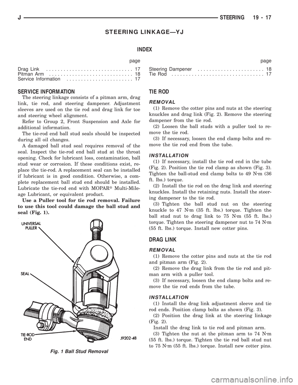
Use a Puller tool for tie rod removal. Failure
to use this tool could damage the ball stud and
seal (Fig. 1).
TIE ROD
REMOVAL
(1) Remove the cotter pins and nuts at the steering
knuckles and drag link (Fig. 2). Remove the steering
dampener from the tie rod.
(2) Loosen the ball studs with a puller tool to re-
move the tie rod.
(3) If necessary, loosen the end clamp bolts and re-
move the tie rod end from the tube.
INSTALLATION
(1) If necessary, install the tie rod end in the tube
(Fig. 2). Position the tie rod clamp as shown (Fig. 3).
Tighten the ball-stud end clamp bolts to 49 Nzm (36
ft. lbs.) torque.
(2) Install the tie rod on the drag link and steering
knuckles. Install the retaining nuts. Install the steer-
ing dampener to the tie rod.
(3) Tighten the ball stud nut on the steering
knuckle to 47 Nzm (35 ft. lbs.) torque. Tighten the
ball stud nut to drag link to 75 Nzm (55 ft. lbs.)
torque. Tighten the steering dampener nut to 74 Nzm
(55 ft. lbs.) torque. Install new cotter pins.
DRAG LINK
REMOVAL
(1) Remove the cotter pins and nuts at the tie rod
and pitman arm (Fig. 2).
(2) Remove the drag link from the tie rod and pit-
man arm with a puller tool.
(3) If necessary, loosen the end clamp bolts and re-
move the tie rod ends from the tube.
INSTALLATION
(1) Install the drag link adjustment sleeve and tie
rod ends. Position clamp bolts as shown (Fig. 3).
(2) Position the drag link at the steering linkage
(Fig. 2).
Install the drag link to tie rod and pitman arm.
(3) Tighten the nut at the pitman arm to 74 Nzm
(55 ft. lbs.) torque. Tighten the tie rod ball stud nut
to 75 Nzm (55 ft. lbs.) torque. Install new cotter pins.
Fig. 1 Ball Stud Removal
JSTEERING 19 - 17
Page 1446 of 1784
²Noise
²Handling
²Durability
²Tread life
²Traction
²Rolling resistance
²Speed capability
Original equipment tires should be used when re-
placement is needed.
Refer to the placard on the vehicle or the
Owner's Manual for the correct replacement
tire.
Failure to use original or equivalent replacement
tires may adversely affect the handling of the vehi-
cle.
The use of oversize tiresis not recommended.
They may cause interference with vehicle suspension
and steering travel. This can cause tire damage or
failure.
WARNING: FAILURE TO EQUIP THE VEHICLE WITH
TIRES HAVING ADEQUATE LOAD CAPABILITY CAN
RESULT IN SUDDEN TIRE FAILURE.
ROTATION
Tires on the front and rear axles operate at differ-
ent loads and perform different steering, driving, and
braking functions. For these reasons, the tires wear
at unequal rates. They may also develop irregular
wear patterns. These effects can be reduced by rotat-
ing the tires according to the maintenance schedule
in the Owners Manual. This will improve tread life,
traction and maintain a smooth quiet ride.
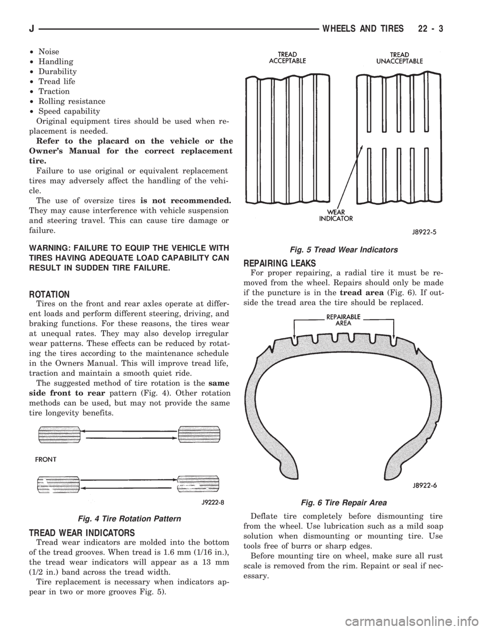
The suggested method of tire rotation is thesame
side front to rearpattern (Fig. 4). Other rotation
methods can be used, but may not provide the same
tire longevity benefits.
TREAD WEAR INDICATORS
Tread wear indicators are molded into the bottom
of the tread grooves. When tread is 1.6 mm (1/16 in.),
the tread wear indicators will appear as a 13 mm
(1/2 in.) band across the tread width.
Tire replacement is necessary when indicators ap-
pear in two or more grooves Fig. 5).
REPAIRING LEAKS
For proper repairing, a radial tire it must be re-
moved from the wheel. Repairs should only be made
if the puncture is in thetread area(Fig. 6). If out-
side the tread area the tire should be replaced.
Deflate tire completely before dismounting tire
from the wheel. Use lubrication such as a mild soap
solution when dismounting or mounting tire. Use
tools free of burrs or sharp edges.
Before mounting tire on wheel, make sure all rust
scale is removed from the rim. Repaint or seal if nec-
essary.
Fig. 4 Tire Rotation Pattern
Fig. 5 Tread Wear Indicators
Fig. 6 Tire Repair Area
JWHEELS AND TIRES 22 - 3
Page 1452 of 1784
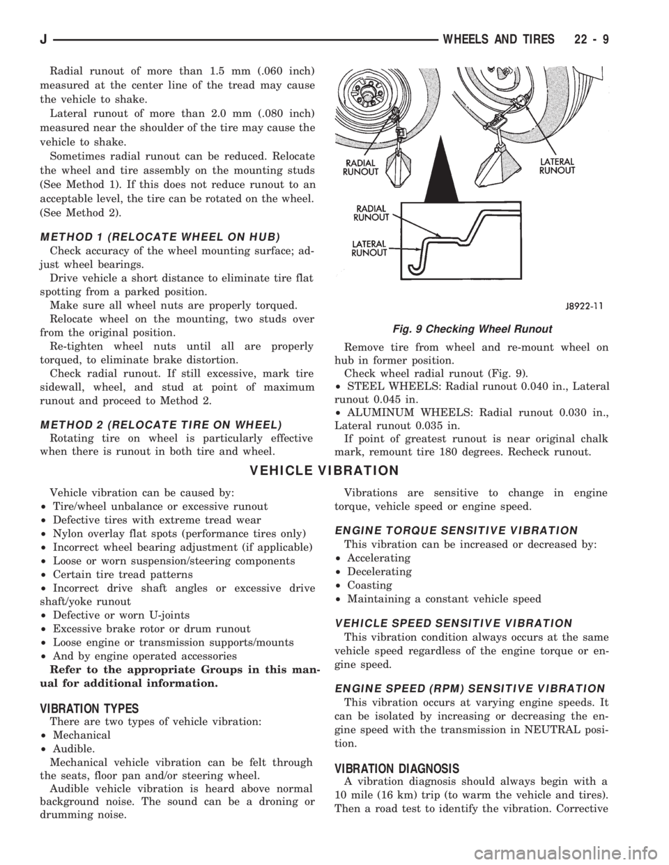
Radial runout of more than 1.5 mm (.060 inch)
measured at the center line of the tread may cause
the vehicle to shake.
Lateral runout of more than 2.0 mm (.080 inch)
measured near the shoulder of the tire may cause the
vehicle to shake.
Sometimes radial runout can be reduced. Relocate
the wheel and tire assembly on the mounting studs
(See Method 1). If this does not reduce runout to an
acceptable level, the tire can be rotated on the wheel.
(See Method 2).
METHOD 1 (RELOCATE WHEEL ON HUB)
Check accuracy of the wheel mounting surface; ad-
just wheel bearings.
Drive vehicle a short distance to eliminate tire flat
spotting from a parked position.
Make sure all wheel nuts are properly torqued.
Relocate wheel on the mounting, two studs over
from the original position.
Re-tighten wheel nuts until all are properly
torqued, to eliminate brake distortion.
Check radial runout. If still excessive, mark tire
sidewall, wheel, and stud at point of maximum
runout and proceed to Method 2.
METHOD 2 (RELOCATE TIRE ON WHEEL)
Rotating tire on wheel is particularly effective
when there is runout in both tire and wheel.Remove tire from wheel and re-mount wheel on
hub in former position.
Check wheel radial runout (Fig. 9).
²STEEL WHEELS: Radial runout 0.040 in., Lateral
runout 0.045 in.
²ALUMINUM WHEELS: Radial runout 0.030 in.,
Lateral runout 0.035 in.
If point of greatest runout is near original chalk
mark, remount tire 180 degrees. Recheck runout.
VEHICLE VIBRATION
Vehicle vibration can be caused by:
²Tire/wheel unbalance or excessive runout
²Defective tires with extreme tread wear
²Nylon overlay flat spots (performance tires only)
²Incorrect wheel bearing adjustment (if applicable)
²Loose or worn suspension/steering components
²Certain tire tread patterns
²Incorrect drive shaft angles or excessive drive
shaft/yoke runout
²Defective or worn U-joints
²Excessive brake rotor or drum runout
²Loose engine or transmission supports/mounts
²And by engine operated accessories
Refer to the appropriate Groups in this man-
ual for additional information.
VIBRATION TYPES
There are two types of vehicle vibration:
²Mechanical
²Audible.
Mechanical vehicle vibration can be felt through
the seats, floor pan and/or steering wheel.
Audible vehicle vibration is heard above normal
background noise. The sound can be a droning or
drumming noise.Vibrations are sensitive to change in engine
torque, vehicle speed or engine speed.
ENGINE TORQUE SENSITIVE VIBRATION
This vibration can be increased or decreased by:
²Accelerating
²Decelerating
²Coasting
²Maintaining a constant vehicle speed
VEHICLE SPEED SENSITIVE VIBRATION
This vibration condition always occurs at the same
vehicle speed regardless of the engine torque or en-
gine speed.
ENGINE SPEED (RPM) SENSITIVE VIBRATION
This vibration occurs at varying engine speeds. It
can be isolated by increasing or decreasing the en-
gine speed with the transmission in NEUTRAL posi-
tion.
VIBRATION DIAGNOSIS
A vibration diagnosis should always begin with a
10 mile (16 km) trip (to warm the vehicle and tires).
Then a road test to identify the vibration. Corrective
Fig. 9 Checking Wheel Runout
JWHEELS AND TIRES 22 - 9
Page 1454 of 1784
mph (112 km/h) range. The incorrect angles can also
produce an audible vibration in the 20 - 50 mph (32 -
80 km/h) range. Caster adjustment could be required
to correct the angles.
UJÐUniversal Joints:Engine torque/vehicle
speed sensitive, mechanical/audible vibration. If the
U-joint is worn it will cause vibration with almost
any vehicle speed/engine torque condition.
DSYÐDrive Shaft and Yokes:Vehicle speed sen-
sitive, mechanical/audible vibration. The condition
will not cause vibration below 35 mph (56 km/h). Ex-
cessive runout, unbalance or dents and bends in the
shaft will cause the vibration. Identify the actual
cause and repair/replace as necessary.
WBÐWheel Bearings:Vehicle speed sensitive,
mechanical/audible vibration. Loose wheel bearings
cause shimmy-like vibration at 35 mph (56 km/h)
and above. Worn bearings will also produce a growl
noise at low vehicle speed and a whine noise at high
vehicle speed. The wheel bearings must be adjusted
or replaced, as applicable.
ANÐAxle Noise:Engine torque/vehicle speed sen-
sitive, mechanical/audible vibration. The axle will not
cause mechanical vibration unless the axle shaft is
bent. Worn or damaged axle pinion shaft or differen-
tial gears and bearings will cause noise. Replace the
defective component(s) as necessary.
SSCÐSuspension and Steering Components:
Vehicle speed sensitive, mechanical vibration. Wornsuspension/steering components can cause mechani-
cal vibration at speeds above 20 mph (32 km/h).
Identify and repair or replace the defective compo-
nent(s).
EAÐEngine Driven Accessories:Engine speed
sensitive, mechanical/audible vibration. Vibration can
be caused by loose or broken A/C compressor, PS
pump, water pump, generator or brackets, etc. Usu-
ally more noticeable when the transmission is shifted
into the NEUTRAL position and the engine speed
(rpm) increased. Inspect the engine driven accesso-
ries in the engine compartment. Repair/replace as
necessary.
ADBÐAccessory Drive Belts:Engine speed sen-
sitive, audible vibration. Worn drive belts can cause a
vibration that produces either a droning, fluttering or
rumbling noise. Inspect the drive belt(s) and tighten/
replace as necessary.
DEMÐDamaged Engine or Transmission Sup-
port Mounts:Engine speed sensitive, mechanical/
audible vibration. If a support mount is worn, noise
or vibration will occur. Inspect the support mounts
and repair/replace as necessary.
ESÐExhaust System:Engine speed sensitive,
mechanical/audible vibration. If loose exhaust compo-
nents contact the vehicle body they will cause noise
and vibration. Inspect the exhaust system for loose,
broken and mis-aligned components and repair/re-
place as necessary.
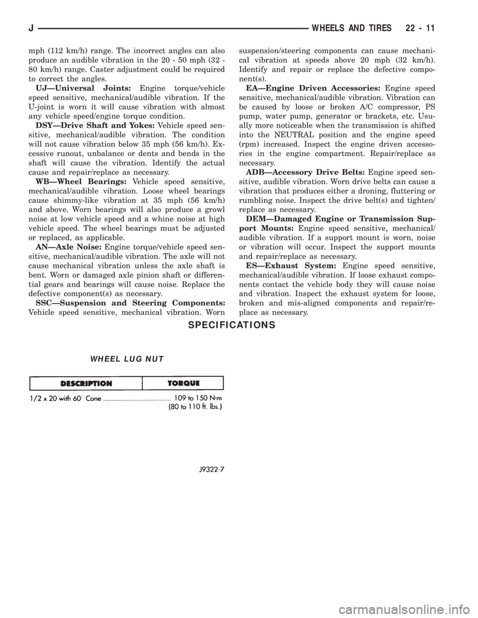
SPECIFICATIONS
WHEEL LUG NUT
JWHEELS AND TIRES 22 - 11
Page 1731 of 1784
NOTE: Groups with the suffix ª-Sº are supplements to
the original service manual publication.
GROUP TAB LOCATOR PAGE
INIntroduction
0Lubrication and Maintenance
2Front Suspension and Axle
3Rear Suspension and Axles
5Brakes
6Clutch
7Cooling System
8Electrical
9Engines
11Exhaust System and Intake Manifold
13Frame and Bumpers
14Fuel System
16Propeller Shafts
19Steering
21Transmissions and Transfer Cases
22Wheels and Tires
23Body Components
24Heating and Air Conditioning
24-SAir Conditioning
25Emission Control Systems
Index
Index Supplement
Service Manual Comment Forms (Rear of Manual)
Page 1745 of 1784
30RH/32RH AUTOMATIC TRANSMISSION . . . 21-66
30RH/32RH GENERAL SPECIFICATIONS . . . 21-322
30RH/32RH IN-VEHICLE SERVICE.........21-96
30RH/32RH PRESSURE TEST
SPECIFICATIONS....................21-323
30RH/32RH SNAP RING/THRUST
WASHER/THRUST PLATE
SPECIFICATIONS....................21-322
30RH/32RH TORQUE SPECIFICATIONS....21-323
30RH/32RH TRANSMISSION DIAGNOSIS . . . 21-69,
21-77,21-78,21-79,21-80,21-81,21-82,21-83,21-84,
21-85
30RH/32RH TRANSMISSION OVERHAUL . . . 21-112
30RH/32RH TRANSMISSION REMOVAL
AND INSTALLATION..................21-108
3-2 DOWNSHIFT, HYDRAULIC FLOW
DURING FULL THROTTLE..............21-92
3-2 DOWNSHIFT, HYDRAULIC FLOW
DURING PART THROTTLE..............21-91
4WD INDICATOR......................8E-22
4WD INDICATOR INOPERATIVE............8E-4
4WD INDICATOR LAMP..................8E-2
60-WAY CONNECTOR, POWERTRAIN
CONTROL MODULE (PCM).............14-38
ABBREVIATIONS, SYMBOLS, FUSES........8W-6
ABS BRAKE DIAGNOSIS...................5-3
ABS BRAKES, BRAKE BLEEDINGÐWITH.....5-14
ABS COMPONENT SERVICE...............5-47
ABS FAULT DIAGNOSIS................5-4,5-6
ABS OPERATION IN ANTILOCK BRAKING
MODE..............................5-43
ABS OPERATION IN NORMAL BRAKING
MODE..............................5-43
ABS SYSTEM OPERATION................5-39
ABS SYSTEM WIRING AND ELECTRICAL
CIRCUITS............................5-4
ABS WARNING LIGHT DISPLAY.............5-3
ABSOLUTE PRESSURE (MAP) SENSOR,
MANIFOLD; FUEL SYSTEM.............14-57
ABSOLUTE PRESSURE (MAP) SENSOR,
MANIFOLD; IGNITION SYSTEMS....8D-5,8D-27
ABSOLUTE PRESSURE (MAP) SENSORÐ
PCM INPUT, MANIFOLD...............14-21
ABSOLUTE PRESSURE (MAP) SENSOR
TEST, MANIFOLD; FUEL SYSTEM........14-44
ABSOLUTE PRESSURE (MAP) SENSOR
TEST, MANIFOLD; IGNITION
SYSTEMS..........................8D-14
ABSORBER, SHOCK; FRONT
SUSPENSION AND AXLE............2-12,2-14
ABSORBER, SHOCK; REAR SUSPENSION
AND AXLES........................3-3,3-5
A/C BLOWER MOTOR...................24-43
A/C CONDENSER......................24-42
A/C CONTROL PANEL...................24-41
A/C CONTROL PANEL REPLACEMENT,
HEATER ............................24-26
A/C OPERATION........................24-1
A/C PERFORMANCE TEST................24-8
A/C RECIRCULATING AIR DOOR
VACUUM MOTOR REPLACEMENT........24-31
ACCELERATION SENSOR INSTALLATION.....5-52
ACCELERATION SENSOR REMOVAL........5-52
ACCELERATION SWITCH.................5-41
ACCELERATION SWITCH OPERATION.......5-45
ACCELERATOR PEDAL..................14-16
ACCELERATOR PEDAL AND THROTTLE
CABLE........................14-16,14-54
ACCENT PAINT.......................23-202
ACCESSORY DRIVE BELT.................0-20
ACCESSORY DRIVE BELTS, ENGINE........7-31
ACCUMULATOR PISTONS AND SPRINGS . . 21-179
ACTUATOR MOTOR STALL TEST...........8P-6
ADAPTER HOUSING AND PARK LOCK
COMPONENT OVERHAUL.............21-120
ADAPTER HOUSING SEAL REPLACEMENT . . 21-182
ADD-A-TRUNK.......................23-199
ADJUSTER PLUG ASSEMBLY
REPLACEMENT......................19-27
ADJUSTMENT, BRAKELIGHT SWITCH.......5-66
ADJUSTMENT, DIFFERENTIAL SHIM
PACK MEASUREMENT..................2-42
ADJUSTMENT, DOOR LATCH
.............23-55
ADJUSTMENT, DRUM BRAKE
..............5-35
ADJUSTMENT, FOG LAMP BEAM
..........8L-12
ADJUSTMENT, FRONT BAND
.............21-99ADJUSTMENT, HEADLAMP BEAM..........8L-3
ADJUSTMENT, HOOD....................23-9
ADJUSTMENT, LIFTGATE................23-70
ADJUSTMENTÐMAJOR, DOOR
ALIGNMENT.........................23-47
ADJUSTMENTÐMINOR, DOOR
ALIGNMENT.........................23-46
ADJUSTMENT, PARK INTERLOCK CABLE . . . 21-186
ADJUSTMENT, PARKING BRAKE...........5-63
ADJUSTMENT, PRELIMINARY
INSPECTION.......................21-167
ADJUSTMENT PROCEDURES,
TRANSMISSION ASSEMBLY...........21-146
ADJUSTMENT, REAR BAND..............21-99
ADJUSTMENT, SHIFT CABLE............21-186
ADJUSTMENT, SHIFT LINKAGE....21-275,21-296
ADJUSTMENT, TAILGATE...............23-160
ADJUSTMENT, TRANSMISSION
ASSEMBLY..............21-15,21-51,21-255
ADJUSTMENT, TRANSMISSION
THROTTLE CABLE..............21-98,21-185
ADJUSTMENT, TRANSMISSION
THROTTLE VALVE CABLE..............21-70
ADJUSTMENT, VALVE BODY ASSEMBLY . . . 21-144
ADJUSTMENT, WHEEL SENSOR AIR GAP....5-49
ADJUSTMENT (XJ), PARK INTERLOCK
CABLE.............................21-97
ADJUSTMENT (XJ), SHIFT CABLE.........21-97
ADJUSTMENT (YJ), GEARSHIFT LINKAGE . . . 21-96
ADJUSTMENTS, ALIGNMENT
MEASUREMENTS......................2-6
ADJUSTMENTS IN VEHICLE, GEAR........19-37
ADJUSTMENTS ON BENCH, GEAR.........19-42
ADJUSTMENTS, SPECIFICATIONS AND
BAND..............................21-66
ADJUSTMENTS, STEERING GEAR.........19-22
AIR CLEANER..........................25-7
AIR CLEANER FILTER ELEMENT, ENGINE....0-16
AIR CLEANER HOUSING; EMISSION
CONTROL SYSTEMS...................25-8
AIR CLEANER HOUSING; FUEL SYSTEM....14-54
AIR CONDITIONER COMPRESSOR/HOSES/
FITTINGS............................0-21
AIR CONDITIONING CLUTCH RELAY.......14-54
AIR CONDITIONING CLUTCH RELAYÐ
PCM OUTPUT.......................14-24
AIR CONDITIONING CONTROLSÐPCM
INPUT.............................14-19
AIR CONDITIONING, DESCRIPTION........24-41
AIR CONDITIONING SCHEMATIC..........24-25
AIR CONDITIONING SYSTEM DIAGNOSIS . . . 24-12
AIR CONDITIONING SYSTEMÐXJ
VEHICLES..........................24-14
AIR CONDITIONING SYSTEMÐYJ
VEHICLES..........................24-15
AIR CONTROL (IAC) MOTOR, IDLE........14-56
AIR CONTROL (IAC) MOTORÐPCM
OUTPUT, IDLE.......................14-25
AIR CONTROL MOTOR TEST, IDLE........14-46
AIR DEFLECTOR, COWL WEATHERSTRIP
SEAL/CROSSMEMBER.................23-10
AIR DOOR VACUUM MOTOR, FRESH.......24-41
AIR DOOR VACUUM MOTOR
REPLACEMENT, A/C RECIRCULATING.....24-31
AIR EXHAUST GRILLEÐXJ VEHICLES......23-30
AIR FILTER; EMISSION CONTROL
SYSTEMS...........................25-9
AIR FILTER; FUEL SYSTEM..............14-54
AIR GAP ADJUSTMENT, WHEEL SENSOR....5-49
AIR GAP, REAR SPEED SENSOR............5-3
AIR INTAKE DUCT, FRESH...............24-41
AIR PRESSURE TEST...................21-73
AIR, PURGING COMPRESSOR OF.........24-17
AIR TEMPERATURE SENSOR, INTAKE......14-54
AIR TEMPERATURE SENSOR, INTAKE
MANIFOLD.....................8D-5,8D-27
AIR TEMPERATURE SENSORÐPCM
INPUT, INTAKE.......................14-20
AIR TEMPERATURE, SENSOR RESISTANCE
(OHMS)ÐCOOLANT TEMPERATURE
SENSOR/MANIF; FUEL SYSTEM
.........14-43
AIR TEMPERATURE SENSOR TEST,
INTAKE
............................14-43
AIR TEMPERATURE SENSOR TEST,
INTAKE MANIFOLD
...................8D-14
AIR VENTILATION, FRESH
...............24-39AIRFLOW DIAGRAM....................24-23
ALIGNMENT ADJUSTMENTÐMAJOR,
DOOR.............................23-47
ALIGNMENT ADJUSTMENTÐMINOR,
DOOR.............................23-46
ALIGNMENT, FRAME...................13-10
ALIGNMENT, FRONT WHEEL...............2-5
ALIGNMENT, HOOD...................23-138
ALIGNMENT MEASUREMENTS AND
ADJUSTMENTS........................2-6
ALIGNMENTÐMINOR, XJ DOOR..........23-46
ALIGNMENT, REAR AXLE..................3-8
ALIGNMENT SPECIFICATIONSÐXJ
VEHICLES............................2-9
ALIGNMENT SPECIFICATIONSÐYJ VEHICLES . . 2-9
ANALYSIS, BACKLASH AND CONTACT
PATTERN; FRONT SUSPENSION AND AXLE . 2-44
ANALYSIS, BACKLASH AND CONTACT
PATTERN; REAR SUSPENSION AND AXLES . 3-25
ANCHOR AND BUMPER, LIFTGATE
LICENSE PLATE SCREW...............23-72
ANGLE MEASUREMENT, UNIVERSAL
JOINT..............................16-4
ANTENNA, RADIO.......................8F-8
ANTENNA TESTS.......................8F-9
ANTILOCK BRAKE SYSTEM (ABS)...........5-1
ANTI-LOCK BRAKE SYSTEM (ABS)
INDICATOR LAMP.....................8E-2
ANTILOCK BRAKE SYSTEM OPERATION.....5-43
ANTILOCK BRAKING MODE, ABS
OPERATION..........................5-43
ANTI-LOCK INDICATOR..................8E-4
ANTILOCK MODE, VEHICLE RESPONSE.......5-3
APPLICATION CHARTS, GEARTRAIN
OPERATION........................21-159
APPLICATION, PAINT..................23-201
APPLICATION, TRANSMISSION...........21-66
APPLIQUE, RADIATOR GRILLE
...........23-134
APPLIQUEÐXJ VEHICLES, QUARTER
WINDOW
...........................23-29
APRONS, FENDER SPLASH
.............23-147
ARM AND PIVOT ASSEMBLY
REPLACEMENT, FRONT WIPER
...........8K-9
ARM, LOWER SUSPENSION
...............2-11
ARM, PITMAN
...................19-15,19-18
ARM REPLACEMENT, FRONT WIPER
........8K-8
ARM REPLACEMENT, REAR WIPER
........8K-12
ARM, UPPER SUSPENSION
...............2-11
ARMS, ROCKER
....................9-19,9-59
ASH RECEIVER TRAY LAMP, I/P
..........23-92
ASSEMBLY AND ADJUSTMENT
PROCEDURES, TRANSMISSION
........21-146
ASSEMBLY AND ADJUSTMENT,
TRANSMISSION
..........21-15,21-51,21-255
ASSEMBLY AND ADJUSTMENT, VALVE
BODY
.............................21-144
ASSEMBLY, CALIPER
....................5-29
ASSEMBLY, DIFFERENTIAL; FRONT
SUSPENSION AND AXLE
................2-36
ASSEMBLY, DIFFERENTIAL; REAR
SUSPENSION AND AXLES
...............3-19
ASSEMBLY, FINAL; FRONT SUSPENSION
AND AXLE
...........................2-44
ASSEMBLY, FINAL; REAR SUSPENSION
AND AXLES
..........................3-26
ASSEMBLY, FUEL RAIL
..................14-56
ASSEMBLY, GEAR
......................19-41
ASSEMBLY, PRESSURE GAUGE AND
MANIFOLD
...........................24-2
ASSEMBLY REPLACEMENT, ADJUSTER
PLUG
..............................19-27
ASSEMBLY REPLACEMENT, CONNECTOR
AND TERMINAL
......................8W-5
ASSEMBLY REPLACEMENT, FRONT WIPER
ARM AND PIVOT
......................8K-9
ASSEMBLY REPLACEMENT, SOLENOID
AND LATCH
..........................8P-6
ASSEMBLY REPLACEMENTÐXJ VEHICLES,
DRIVE AXLE; FRONT SUSPENSION AND
AXLE
...............................2-21
ASSEMBLY REPLACEMENTÐXJ VEHICLES,
DRIVE AXLE; REAR SUSPENSION AND
AXLES
..........................3-11,3-30
JINDEX1
Description Group-Page Description Group-Page Description Group-Page