1994 JEEP CHEROKEE suspension
[x] Cancel search: suspensionPage 84 of 1784
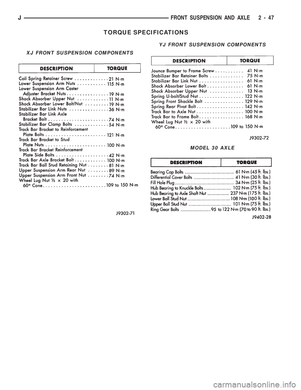
TORQUE SPECIFICATIONS
XJ FRONT SUSPENSION COMPONENTS
YJ FRONT SUSPENSION COMPONENTS
MODEL 30 AXLE
JFRONT SUSPENSION AND AXLE 2 - 47
Page 154 of 1784
SERVICE BRAKE DIAGNOSIS
INDEX
page page
Component Inspection...................... 8
Diagnosing Parking Brake Problems.......... 10
Diagnosing Service Brake Problems........... 8
Diagnosis Procedures...................... 7
General Information........................ 7Master Cylinder/Power Booster Test.......... 11
Power Booster Check Valve Test............ 11
Power Booster Vacuum Test................ 12
Preliminary Brake Check.................... 7
Road Testing............................ 7
GENERAL INFORMATION
The diagnosis information in this section covers
service brake components which include:
²disc brake calipers
²disc brakeshoes
²drum brake wheel cylinders
²drum brakeshoes and brake drums
²drum brake support plates
²parking brake mechanism
²master cylinder/combination valve
²vacuum power brake booster
²brake pedal and brakelight switch
²brake warning light
DIAGNOSIS PROCEDURES
Service brake diagnosis involves determining if a
problem is related to a mechanical, hydraulic or vac-
uum operated component. A preliminary brake
check, followed by road testing and component in-
spection are needed to determine a problem cause.
Road testing will either verify proper brake opera-
tion or confirm the existence of a problem. Compo-
nent inspection will, in most cases, identify the
actual part responsible for a problem.
The first diagnosis step is the preliminary brake
check. This involves inspecting fluid level, parking
brake action, wheel and tire condition, checking for
obvious leaks or component damage and testing
brake pedal response. A road test will confirm or
deny the existence of a problem. The final diagnosis
procedure involves road test analysis and a visual in-
spection of brake components.
PRELIMINARY BRAKE CHECK
(1) If amber antilock light is illuminated, refer to
Antilock Brake System Diagnosis. However, if red
warning light is illuminated, or if neither warning
light is illuminated, continue with diagnosis.
(2) Check condition of tires and wheels. Damaged
wheels and worn, damaged, or underinflated tires
can cause pull, shudder, tramp and a condition simi-
lar to grab.
(3) If complaint was based on noise when braking,
check suspension components. Jounce front and rearof vehicle and listen for noise that might be caused
by loose, worn, or damaged suspension or steering
components.
(4) Inspect brake fluid level:
(a) If vehicle has one-piece master cylinder, fluid
level should be to 6 mm (1/4 in.) of reservoir rim. If
vehicle two-piece, removable reservoir, correct level
is to top of indicator rings in reservoir.
(b) On models with ABS brakes, preferred level
is to MAX mark on reservoir. Acceptable level is
between MAX and MIN marks.
(c) Remember that fluid level in the front and
rear reservoir compartments will decrease in pro-
portion to normal lining wear. However, if fluid
level is abnormally low, look for leaks at calipers,
wheel cylinders, brakelines and master cylinder.
(5) Inspect brake fluid condition:
(a) Fluid should be reasonably clear and free of
foreign material.Note that brake fluid tends to
darken over time. This is normal and should
not be mistaken for contamination. If fluid is
clear of foreign material, it is OK.
(b) If fluid is highly discolored, or appears to con-
tain foreign material, drain out a sample with a
clean suction gun. Pour sample in a glass container
and note condition.
(c) If fluid separates into layers, obviously con-
tains oil, or a substance other than brake fluid,
system seals and cups will have to be replaced and
hydraulic system flushed.
(6) Check parking brake operation. Verify free
movement and full release of cables and foot pedal or
hand lever. Also note if vehicle was being operated
with parking brake partially applied.
(7) Check brake pedal operation. Verify that pedal
does not bind and has adequate free play. If pedal
lacks free play, check pedal and power booster for be-
ing loose or for bind condition. Do not road test until
condition is corrected.
(8) If components inspected look OK, road test the
vehicle.
ROAD TESTING
(1) If amber warning light is illuminated, problem
is with antilock system component. Refer to Antilock
Brake System Diagnosis.
JBRAKES 5 - 7
Page 156 of 1784

Brake drag also has a direct effect on fuel economy.
If undetected, minor brake drag can be misdiagnosed
as an engine or transmission/torque converter prob-
lem.
Minor drag will usually cause slight surface char-
ring of the lining. It can also generate hard spots in
rotors and drums from the overheat/cool down pro-
cess. In most cases, the rotors, drums, wheels and
tires are quite warm to the touch after the vehicle is
stopped.
Severe drag can char the brake lining all the way
through. It can also distort and score rotors and
drums to the point of replacement. The wheels, tires
and brake components will be extremely hot. In se-
vere cases, the lining may generate smoke as it chars
from overheating.
An additional cause of drag involves the use of in-
correct length caliper mounting bolts. Bolts that are
too long can cause a partial apply condition. The cor-
rect caliper bolts have a shank length of 67 mm
(2.637 in.), plus or minus 0.6 mm (0.0236 in.). Refer
to the Disc Brake service section for more detail on
caliper bolt dimensions and identification.
Some common causes of brake drag are:
²loose or damaged wheel bearing
²seized or sticking caliper or wheel cylinder piston
²caliper binding on bushings or slide surfaces
²wrong length caliper mounting bolts (too long)
²loose caliper mounting bracket
²distorted brake drum or shoes
²rear brakeshoes binding on worn/damaged support
plates
²severely rusted/corroded components
²misassembled components.
If brake drag occurs at all wheels, the problem may
be related to a blocked master cylinder compensator
port or faulty power booster (binds-does not release).
The brakelight switch can also be a cause of drag.
An improperly mounted or adjusted brakelight
switch can prevent full brake pedal return. The re-
sult will be the same as if the master cylinder com-
pensator ports are blocked. The brakes would be
partially applied causing drag.
BRAKE FADE
Brake fade is a product of overheating caused by
brake drag. However, overheating and subsequent
fade can also be caused by riding the brake pedal,
making repeated high deceleration stops in a short
time span, or constant braking on steep roads. Refer
to the Brake Drag information in this section for
causes.
PEDAL PULSATION
Pedal pulsation is caused by components that are
loose, or beyond tolerance limits.
Disc brake rotors with excessive lateral runout or
thickness variation, or out of round brake drums arethe primary causes of pulsation. Other causes are
loose wheel bearings or calipers and worn, damaged
tires.
PULL
A front pull condition could be the result of:
²contaminated lining in one caliper
²seized caliper piston
²binding caliper
²wrong caliper mounting bolts (too long)
²loose caliper
²loose or corroded mounting bolts
²improper brakeshoes
²damaged rotor
²incorrect wheel bearing adjustment (at one wheel)
A worn, damaged wheel bearing or suspension
component are further causes of pull. A damaged
front tire (bruised, ply separation) can also cause
pull. Wrong caliper bolts (too long) will cause a par-
tial apply condition and pull if only one caliper is in-
volved.
A common and frequently misdiagnosed pull condi-
tion is where direction of pull changes after a few
stops. The cause is a combination of brake drag fol-
lowed by fade at the dragging brake unit.
As the dragging brake overheats, efficiency is so
reduced that fade occurs. If the opposite brake unit is
still functioning normally, its braking effect is mag-
nified. This causes pull to switch direction in favor of
the brake unit that is functioning normally.
When diagnosing a change in pull condition, re-
member that pull will return to the original direction
if the dragging brake unit is allowed to cool down
(and is not seriously damaged).
REAR BRAKE GRAB
Rear grab (or pull) is usually caused by contami-
nated lining, bent or binding shoes and support
plates, or improperly assembled components. This is
particularly true when only one rear wheel is in-
volved. However, when both rear wheels are affected,
the master cylinder or proportioning valve could be
at fault.
BRAKES DO NOT HOLD AFTER DRIVING
THROUGH DEEP WATER PUDDLES
This condition is generally caused by water soaked
lining. If the lining is only wet, it can be dried by
driving with the brakes lightly applied for a mile or
two. However, if the lining is both wet and dirty, dis-
assembly and cleaning will be necessary.
BRAKE FLUID CONTAMINATION
There are two basic causes of brake fluid contami-
nation. The first involves allowing dirt, debris, or
other liquid materials to enter the cylinder reservoirs
JBRAKES 5 - 9
Page 157 of 1784

when the cover is off. The second involves adding to,
or filling the cylinder reservoirs with a non-recom-
mended fluid.
Brake fluid contaminated with only dirt, or debris
usually retains a normal appearance. In some cases,
the foreign material will remain suspended in the
fluid and be visible. The fluid and foreign material
can be removed from the reservoir with a suction
gun but only if the brakes have not been applied. If
the brakes are applied after contamination, system
flushing will be required. The master cylinder may
also have to be disassembled, cleaned and the piston
seals replaced. Foreign material lodged in the reser-
voir compensator/return ports can cause brake drag
by restricting fluid return after brake application.
Brake fluid contaminated by a non-recommended
fluid will usually be discolored, milky, oily looking,
or foamy. In some cases, it may even appear as if the
fluid contains sludge.However, remember that
brake fluid will darken in time and occasionally
be cloudy in appearance. These are normal con-
ditions and should not be mistaken for contami-
nation.
If some type of oil has been added to the system,
the fluid will separate into distinct layers. To verify
this, drain off a sample with a clean suction gun.
Then pour the sample into a glass container and ob-
serve fluid action. If the fluid separates into distinct
layers, it is definitely contaminated.
The only real correction for contamination by non-
recommended fluid is to flush the entire hydraulic
system and replace all the seals.
BRAKE NOISE
Squeak/Squeal
Brake squeak or squeal may be due to linings that
are wet or contaminated with brake fluid, grease, or
oil. Glazed linings and rotors with hard spots can
also contribute to squeak. Dirt and foreign material
embedded in the brake lining will also cause squeak/
squeal.
A very loud squeak or squeal is frequently a sign
of severely worn brake lining. If the lining has worn
through to the brakeshoes in spots, metal-to-metal
contact occurs. If the condition is allowed to continue,
rotors can become so scored that replacement is nec-
essary.
Thump/Clunk
Thumping or clunk noises during braking are fre-
quentlynotcaused by brake components. In many
cases, such noises are caused by loose or damaged
steering, suspension, or engine components. How-
ever, calipers that bind on the slide surfaces can gen-
erate a thump or clunk noise. In addition, worn out,
improperly adjusted, or improperly assembled rear
brakeshoes can also produce a thump noise.Chatter/Shudder
Brake chatter, or shudder is usually caused by
loose or worn components, or glazed/burnt lining. Ro-
tors with hard spots can also contribute to chatter.
Additional causes of chatter are out of tolerance ro-
tors, brake lining not securely attached to the shoes,
loose wheel bearings and contaminated brake lining.
BRAKELINING CONTAMINATION
Brakelining contamination is usually a product of
leaking calipers or wheel cylinders, driving through
deep water puddles, or lining that has become cov-
ered with grease and grit during repair.
WHEEL AND TIRE PROBLEMS
Some conditions attributed to brake components
may actually be caused by a wheel or tire problem.
A damaged wheel can cause shudder, vibration and
pull. A worn or damaged tire can also cause pull.
Severely worn tires with very little tread left can
produce a condition similar to grab as the tire loses
and recovers traction.
Flat-spotted tires can cause vibration and wheel
tramp and generate shudder during brake operation.
A tire with internal damage such as a severe
bruise or ply separation can cause pull and vibration.
DIAGNOSING PARKING BRAKE PROBLEMS
Adjustment Mechanism
Parking brake adjustment is controlled by a
cable tensioner mechanism. This applies to 1991
through 1994 YJ models and 1992 and later XJ
models. The cable tensioner, once adjusted at
the factory, will not need further adjustment un-
der normal circumstances. There are only two
instances when adjustment is required. The first
is when a new tensioner, or cables have been in-
stalled. And the second, is when the tensioner
and cables are disconnected for access to other
brake components.
Parking Brake problem Causes
In most cases, the actual cause of an improperly
functioning parking brake (too loose/too tight/wont
hold), can be traced to a drum brake component.
The leading cause of improper parking brake
operation, is excessive clearance between the
brakeshoes and the drum surface. Excessive
clearance is a result of: lining and/or drum wear;
oversize drums; or inoperative shoe adjuster
components.
Excessive parking brake lever travel (sometimes
described as a loose lever or too loose condition), is
the result of worn brakeshoes/drums, improper
brakeshoe adjustment, or mis-assembled brake parts.
A ``too loose'' condition can also be caused by inop-
erative brakeshoe adjusters. If the adjusters are mis-
5 - 10 BRAKESJ
Page 173 of 1784
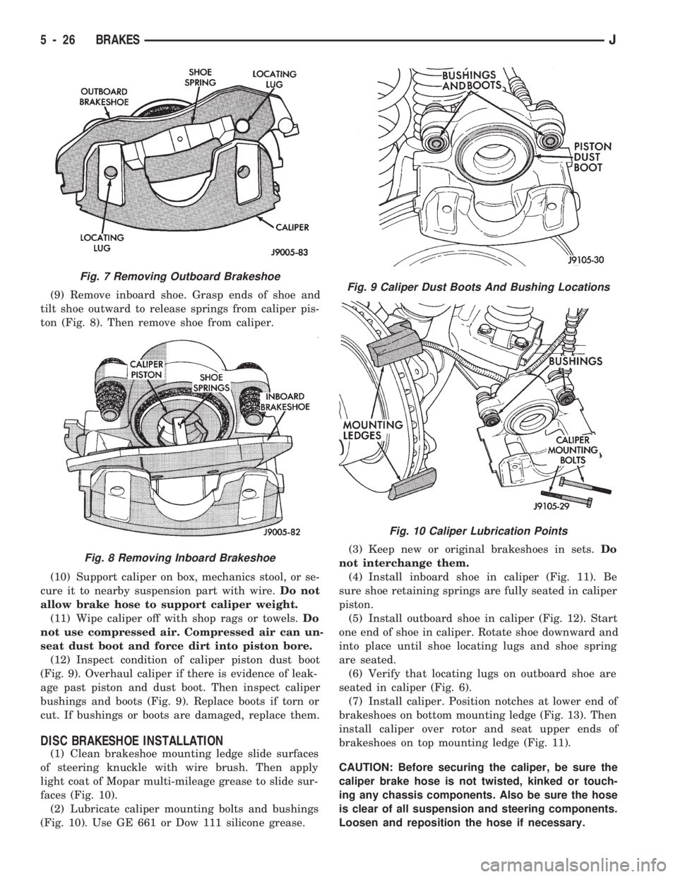
(9) Remove inboard shoe. Grasp ends of shoe and
tilt shoe outward to release springs from caliper pis-
ton (Fig. 8). Then remove shoe from caliper.
(10) Support caliper on box, mechanics stool, or se-
cure it to nearby suspension part with wire.Do not
allow brake hose to support caliper weight.
(11) Wipe caliper off with shop rags or towels.Do
not use compressed air. Compressed air can un-
seat dust boot and force dirt into piston bore.
(12) Inspect condition of caliper piston dust boot
(Fig. 9). Overhaul caliper if there is evidence of leak-
age past piston and dust boot. Then inspect caliper
bushings and boots (Fig. 9). Replace boots if torn or
cut. If bushings or boots are damaged, replace them.
DISC BRAKESHOE INSTALLATION
(1) Clean brakeshoe mounting ledge slide surfaces
of steering knuckle with wire brush. Then apply
light coat of Mopar multi-mileage grease to slide sur-
faces (Fig. 10).
(2) Lubricate caliper mounting bolts and bushings
(Fig. 10). Use GE 661 or Dow 111 silicone grease.(3) Keep new or original brakeshoes in sets.Do
not interchange them.
(4) Install inboard shoe in caliper (Fig. 11). Be
sure shoe retaining springs are fully seated in caliper
piston.
(5) Install outboard shoe in caliper (Fig. 12). Start
one end of shoe in caliper. Rotate shoe downward and
into place until shoe locating lugs and shoe spring
are seated.
(6) Verify that locating lugs on outboard shoe are
seated in caliper (Fig. 6).
(7) Install caliper. Position notches at lower end of
brakeshoes on bottom mounting ledge (Fig. 13). Then
install caliper over rotor and seat upper ends of
brakeshoes on top mounting ledge (Fig. 11).
CAUTION: Before securing the caliper, be sure the
caliper brake hose is not twisted, kinked or touch-
ing any chassis components. Also be sure the hose
is clear of all suspension and steering components.
Loosen and reposition the hose if necessary.
Fig. 7 Removing Outboard Brakeshoe
Fig. 8 Removing Inboard Brakeshoe
Fig. 9 Caliper Dust Boots And Bushing Locations
Fig. 10 Caliper Lubrication Points
5 - 26 BRAKESJ
Page 177 of 1784
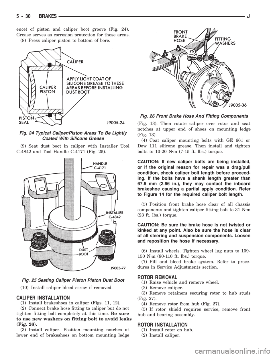
ence) of piston and caliper boot groove (Fig. 24).
Grease serves as corrosion protection for these areas.
(8) Press caliper piston to bottom of bore.
(9) Seat dust boot in caliper with Installer Tool
C-4842 and Tool Handle C-4171 (Fig. 25).
(10) Install caliper bleed screw if removed.
CALIPER INSTALLATION
(1) Install brakeshoes in caliper (Figs. 11, 12).
(2) Connect brake hose fitting to caliper but do not
tighten fitting bolt completely at this time.Be sure
to use new washers on fitting bolt to avoid leaks
(Fig. 26).
(3) Install caliper. Position mounting notches at
lower end of brakeshoes on bottom mounting ledge(Fig. 13). Then rotate caliper over rotor and seat
notches at upper end of shoes on mounting ledge
(Fig. 13).
(4) Coat caliper mounting bolts with GE 661 or
Dow 111 silicone grease. Then install and tighten
bolts to 10-20 Nzm (7-15 ft. lbs.) torque.
CAUTION: If new caliper bolts are being installed,
or if the original reason for repair was a drag/pull
condition, check caliper bolt length before proceed-
ing. If the bolts have a shank length greater than
67.6 mm (2.66 in.), they may contact the inboard
brakeshoe causing a partial apply condition. Refer
to Figure 14 for the required caliper bolt length.
(5) Position front brake hose clear of all chassis
components and tighten caliper fitting bolt to 31 Nzm
(23 ft. lbs.) torque.
CAUTION: Be sure the brake hose is not twisted or
kinked at any point. Also be sure the hose is clear
of all steering and suspension components. Loosen
and reposition the hose if necessary.
(6) Install wheels. Tighten wheel lug nuts to 109-
150 Nzm (80-110 ft. lbs.) torque.
(7) Fill and bleed brake system. Refer to proce-
dures in Service Adjustments section.
ROTOR REMOVAL
(1) Raise vehicle and remove wheel.
(2) Remove caliper.
(3) Remove retainers securing rotor to hub studs
(Fig. 27).
(4) Remove rotor from hub (Fig. 27).
(5) If rotor shield requires service, remove front
hub and bearing assembly.
ROTOR INSTALLATION
(1) Install rotor on hub.
(2) Install caliper.
Fig. 24 Typical Caliper/Piston Areas To Be Lightly
Coated With Silicone Grease
Fig. 25 Seating Caliper Piston Piston Dust Boot
Fig. 26 Front Brake Hose And Fitting Components
5 - 30 BRAKESJ
Page 961 of 1784
(1) Disconnect the battery negative cable.
(2) Disconnect all wire harness connectors that
connect body wire harnesses to the frame wire har-
nesses.
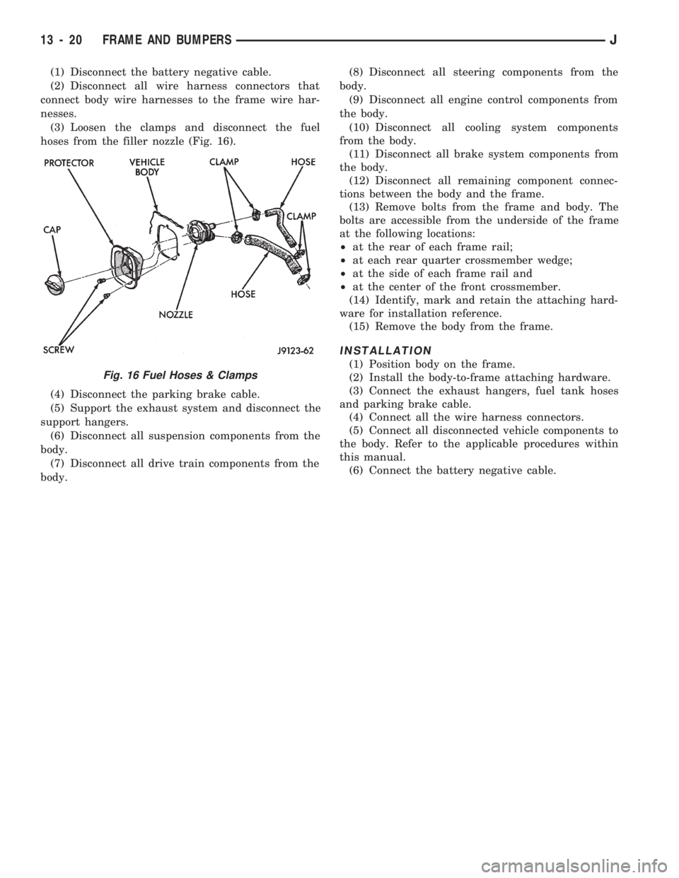
(3) Loosen the clamps and disconnect the fuel
hoses from the filler nozzle (Fig. 16).
(4) Disconnect the parking brake cable.
(5) Support the exhaust system and disconnect the
support hangers.
(6) Disconnect all suspension components from the
body.
(7) Disconnect all drive train components from the
body.(8) Disconnect all steering components from the
body.
(9) Disconnect all engine control components from
the body.
(10) Disconnect all cooling system components
from the body.
(11) Disconnect all brake system components from
the body.
(12) Disconnect all remaining component connec-
tions between the body and the frame.
(13) Remove bolts from the frame and body. The
bolts are accessible from the underside of the frame
at the following locations:
²at the rear of each frame rail;
²at each rear quarter crossmember wedge;
²at the side of each frame rail and
²at the center of the front crossmember.
(14) Identify, mark and retain the attaching hard-
ware for installation reference.
(15) Remove the body from the frame.
INSTALLATION
(1) Position body on the frame.
(2) Install the body-to-frame attaching hardware.
(3) Connect the exhaust hangers, fuel tank hoses
and parking brake cable.
(4) Connect all the wire harness connectors.
(5) Connect all disconnected vehicle components to
the body. Refer to the applicable procedures within
this manual.
(6) Connect the battery negative cable.
Fig. 16 Fuel Hoses & Clamps
13 - 20 FRAME AND BUMPERSJ
Page 1028 of 1784
²Have a 3 degree maximum operating angle
²Have at least a 1/2 degree continuous operating
(propeller shaft) angle
Engine speed (R.P.M.) is the main factor though in
determining maximum allowable operating angles.
As a guide to maximum normal operating angles re-
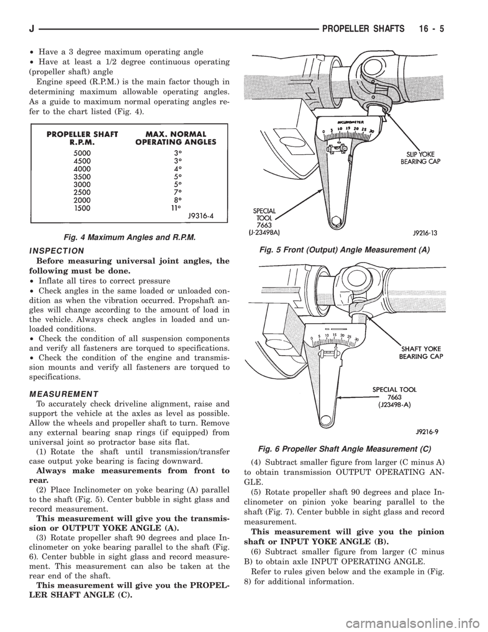
fer to the chart listed (Fig. 4).
INSPECTION
Before measuring universal joint angles, the
following must be done.
²Inflate all tires to correct pressure
²Check angles in the same loaded or unloaded con-
dition as when the vibration occurred. Propshaft an-
gles will change according to the amount of load in
the vehicle. Always check angles in loaded and un-
loaded conditions.
²Check the condition of all suspension components
and verify all fasteners are torqued to specifications.
²Check the condition of the engine and transmis-
sion mounts and verify all fasteners are torqued to
specifications.
MEASUREMENT
To accurately check driveline alignment, raise and
support the vehicle at the axles as level as possible.
Allow the wheels and propeller shaft to turn. Remove
any external bearing snap rings (if equipped) from
universal joint so protractor base sits flat.
(1) Rotate the shaft until transmission/transfer
case output yoke bearing is facing downward.
Always make measurements from front to
rear.
(2) Place Inclinometer on yoke bearing (A) parallel
to the shaft (Fig. 5). Center bubble in sight glass and
record measurement.
This measurement will give you the transmis-
sion or OUTPUT YOKE ANGLE (A).
(3) Rotate propeller shaft 90 degrees and place In-
clinometer on yoke bearing parallel to the shaft (Fig.
6). Center bubble in sight glass and record measure-
ment. This measurement can also be taken at the
rear end of the shaft.
This measurement will give you the PROPEL-
LER SHAFT ANGLE (C).(4) Subtract smaller figure from larger (C minus A)
to obtain transmission OUTPUT OPERATING AN-
GLE.
(5) Rotate propeller shaft 90 degrees and place In-
clinometer on pinion yoke bearing parallel to the
shaft (Fig. 7). Center bubble in sight glass and record
measurement.
This measurement will give you the pinion
shaft or INPUT YOKE ANGLE (B).
(6) Subtract smaller figure from larger (C minus
B) to obtain axle INPUT OPERATING ANGLE.
Refer to rules given below and the example in (Fig.
8) for additional information.
Fig. 4 Maximum Angles and R.P.M.
Fig. 5 Front (Output) Angle Measurement (A)
Fig. 6 Propeller Shaft Angle Measurement (C)
JPROPELLER SHAFTS 16 - 5