1994 JEEP CHEROKEE engine
[x] Cancel search: enginePage 1302 of 1784
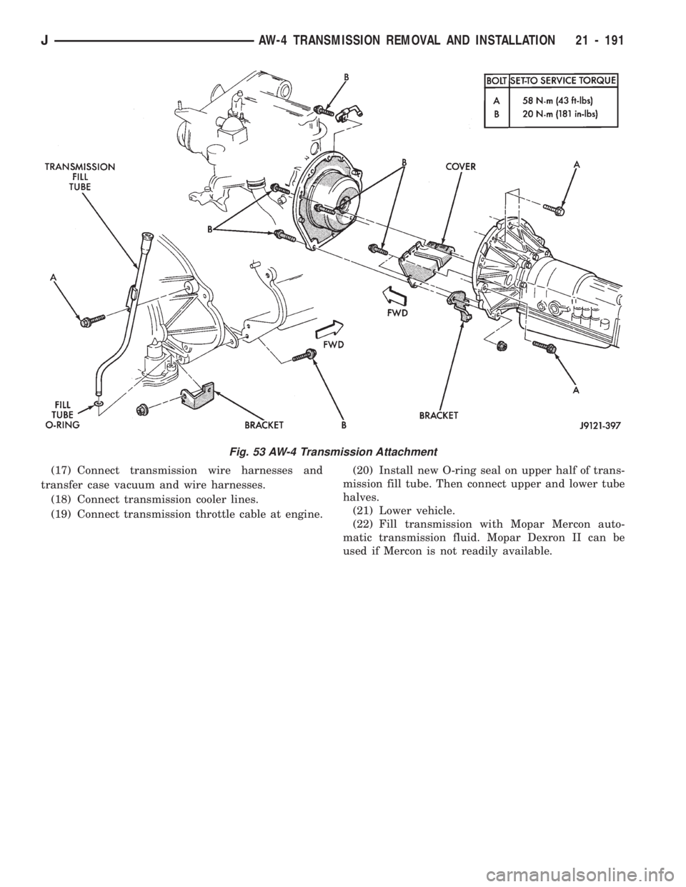
(17) Connect transmission wire harnesses and
transfer case vacuum and wire harnesses.
(18) Connect transmission cooler lines.
(19) Connect transmission throttle cable at engine.(20) Install new O-ring seal on upper half of trans-
mission fill tube. Then connect upper and lower tube
halves.
(21) Lower vehicle.
(22) Fill transmission with Mopar Mercon auto-
matic transmission fluid. Mopar Dexron II can be
used if Mercon is not readily available.
Fig. 53 AW-4 Transmission Attachment
JAW-4 TRANSMISSION REMOVAL AND INSTALLATION 21 - 191
Page 1452 of 1784
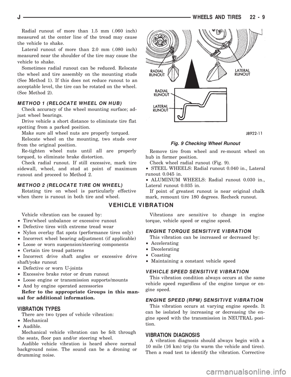
Radial runout of more than 1.5 mm (.060 inch)
measured at the center line of the tread may cause
the vehicle to shake.
Lateral runout of more than 2.0 mm (.080 inch)
measured near the shoulder of the tire may cause the
vehicle to shake.
Sometimes radial runout can be reduced. Relocate
the wheel and tire assembly on the mounting studs
(See Method 1). If this does not reduce runout to an
acceptable level, the tire can be rotated on the wheel.
(See Method 2).
METHOD 1 (RELOCATE WHEEL ON HUB)
Check accuracy of the wheel mounting surface; ad-
just wheel bearings.
Drive vehicle a short distance to eliminate tire flat
spotting from a parked position.
Make sure all wheel nuts are properly torqued.
Relocate wheel on the mounting, two studs over
from the original position.
Re-tighten wheel nuts until all are properly
torqued, to eliminate brake distortion.
Check radial runout. If still excessive, mark tire
sidewall, wheel, and stud at point of maximum
runout and proceed to Method 2.
METHOD 2 (RELOCATE TIRE ON WHEEL)
Rotating tire on wheel is particularly effective
when there is runout in both tire and wheel.Remove tire from wheel and re-mount wheel on
hub in former position.
Check wheel radial runout (Fig. 9).
²STEEL WHEELS: Radial runout 0.040 in., Lateral
runout 0.045 in.
²ALUMINUM WHEELS: Radial runout 0.030 in.,
Lateral runout 0.035 in.
If point of greatest runout is near original chalk
mark, remount tire 180 degrees. Recheck runout.
VEHICLE VIBRATION
Vehicle vibration can be caused by:
²Tire/wheel unbalance or excessive runout
²Defective tires with extreme tread wear
²Nylon overlay flat spots (performance tires only)
²Incorrect wheel bearing adjustment (if applicable)
²Loose or worn suspension/steering components
²Certain tire tread patterns
²Incorrect drive shaft angles or excessive drive
shaft/yoke runout
²Defective or worn U-joints
²Excessive brake rotor or drum runout
²Loose engine or transmission supports/mounts
²And by engine operated accessories
Refer to the appropriate Groups in this man-
ual for additional information.
VIBRATION TYPES
There are two types of vehicle vibration:
²Mechanical
²Audible.
Mechanical vehicle vibration can be felt through
the seats, floor pan and/or steering wheel.
Audible vehicle vibration is heard above normal
background noise. The sound can be a droning or
drumming noise.Vibrations are sensitive to change in engine
torque, vehicle speed or engine speed.
ENGINE TORQUE SENSITIVE VIBRATION
This vibration can be increased or decreased by:
²Accelerating
²Decelerating
²Coasting
²Maintaining a constant vehicle speed
VEHICLE SPEED SENSITIVE VIBRATION
This vibration condition always occurs at the same
vehicle speed regardless of the engine torque or en-
gine speed.
ENGINE SPEED (RPM) SENSITIVE VIBRATION
This vibration occurs at varying engine speeds. It
can be isolated by increasing or decreasing the en-
gine speed with the transmission in NEUTRAL posi-
tion.
VIBRATION DIAGNOSIS
A vibration diagnosis should always begin with a
10 mile (16 km) trip (to warm the vehicle and tires).
Then a road test to identify the vibration. Corrective
Fig. 9 Checking Wheel Runout
JWHEELS AND TIRES 22 - 9
Page 1453 of 1784
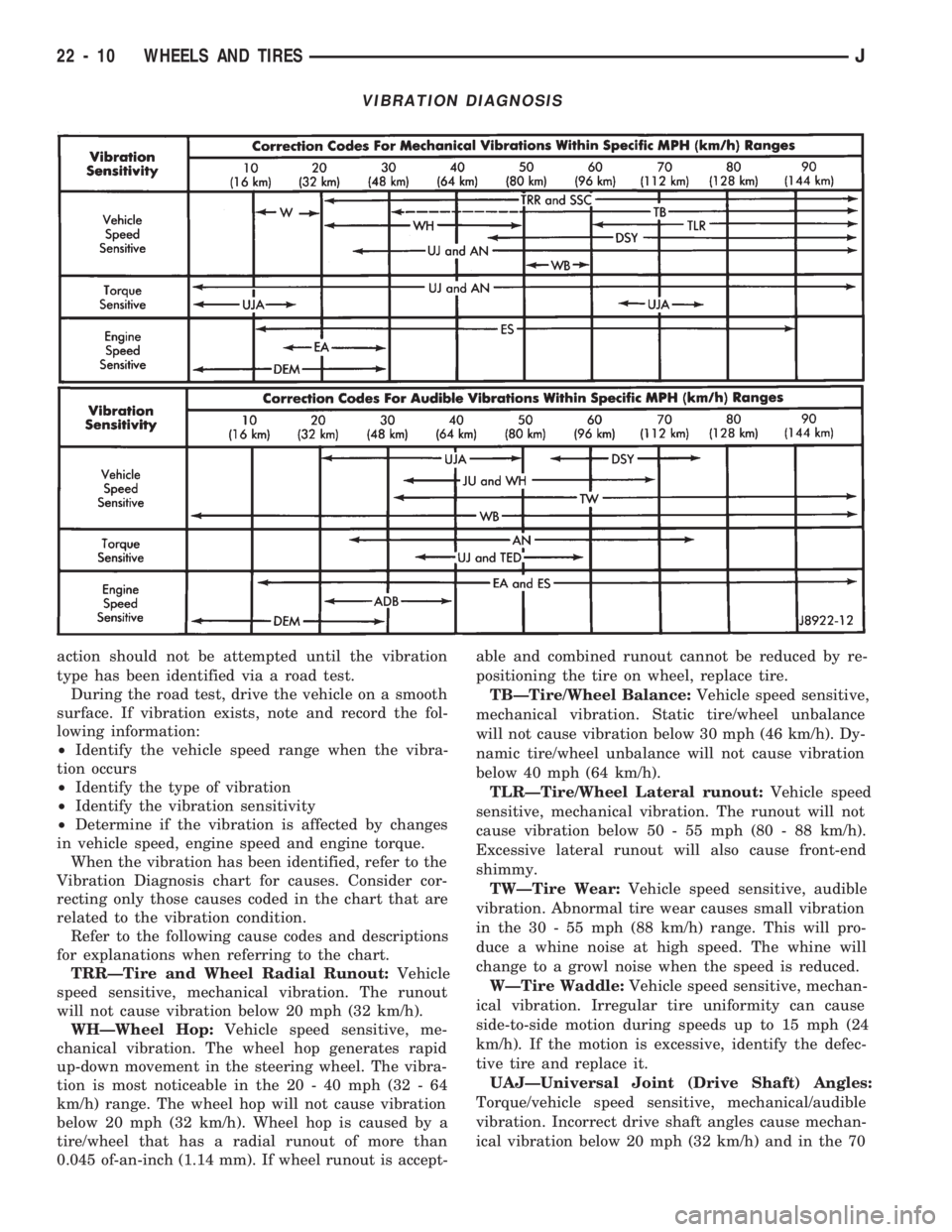
action should not be attempted until the vibration
type has been identified via a road test.
During the road test, drive the vehicle on a smooth
surface. If vibration exists, note and record the fol-
lowing information:
²Identify the vehicle speed range when the vibra-
tion occurs
²Identify the type of vibration
²Identify the vibration sensitivity
²Determine if the vibration is affected by changes
in vehicle speed, engine speed and engine torque.
When the vibration has been identified, refer to the
Vibration Diagnosis chart for causes. Consider cor-
recting only those causes coded in the chart that are
related to the vibration condition.
Refer to the following cause codes and descriptions
for explanations when referring to the chart.
TRRÐTire and Wheel Radial Runout:Vehicle
speed sensitive, mechanical vibration. The runout
will not cause vibration below 20 mph (32 km/h).
WHÐWheel Hop:Vehicle speed sensitive, me-
chanical vibration. The wheel hop generates rapid
up-down movement in the steering wheel. The vibra-
tion is most noticeable in the 20 - 40 mph (32 - 64
km/h) range. The wheel hop will not cause vibration
below 20 mph (32 km/h). Wheel hop is caused by a
tire/wheel that has a radial runout of more than
0.045 of-an-inch (1.14 mm). If wheel runout is accept-able and combined runout cannot be reduced by re-
positioning the tire on wheel, replace tire.
TBÐTire/Wheel Balance:Vehicle speed sensitive,
mechanical vibration. Static tire/wheel unbalance
will not cause vibration below 30 mph (46 km/h). Dy-
namic tire/wheel unbalance will not cause vibration
below 40 mph (64 km/h).
TLRÐTire/Wheel Lateral runout:Vehicle speed
sensitive, mechanical vibration. The runout will not
cause vibration below 50 - 55 mph (80 - 88 km/h).
Excessive lateral runout will also cause front-end
shimmy.
TWÐTire Wear:Vehicle speed sensitive, audible
vibration. Abnormal tire wear causes small vibration
in the 30 - 55 mph (88 km/h) range. This will pro-
duce a whine noise at high speed. The whine will
change to a growl noise when the speed is reduced.
WÐTire Waddle:Vehicle speed sensitive, mechan-
ical vibration. Irregular tire uniformity can cause
side-to-side motion during speeds up to 15 mph (24
km/h). If the motion is excessive, identify the defec-
tive tire and replace it.
UAJÐUniversal Joint (Drive Shaft) Angles:
Torque/vehicle speed sensitive, mechanical/audible
vibration. Incorrect drive shaft angles cause mechan-
ical vibration below 20 mph (32 km/h) and in the 70
VIBRATION DIAGNOSIS
22 - 10 WHEELS AND TIRESJ
Page 1454 of 1784
mph (112 km/h) range. The incorrect angles can also
produce an audible vibration in the 20 - 50 mph (32 -
80 km/h) range. Caster adjustment could be required
to correct the angles.
UJÐUniversal Joints:Engine torque/vehicle
speed sensitive, mechanical/audible vibration. If the
U-joint is worn it will cause vibration with almost
any vehicle speed/engine torque condition.
DSYÐDrive Shaft and Yokes:Vehicle speed sen-
sitive, mechanical/audible vibration. The condition
will not cause vibration below 35 mph (56 km/h). Ex-
cessive runout, unbalance or dents and bends in the
shaft will cause the vibration. Identify the actual
cause and repair/replace as necessary.
WBÐWheel Bearings:Vehicle speed sensitive,
mechanical/audible vibration. Loose wheel bearings
cause shimmy-like vibration at 35 mph (56 km/h)
and above. Worn bearings will also produce a growl
noise at low vehicle speed and a whine noise at high
vehicle speed. The wheel bearings must be adjusted
or replaced, as applicable.
ANÐAxle Noise:Engine torque/vehicle speed sen-
sitive, mechanical/audible vibration. The axle will not
cause mechanical vibration unless the axle shaft is
bent. Worn or damaged axle pinion shaft or differen-
tial gears and bearings will cause noise. Replace the
defective component(s) as necessary.
SSCÐSuspension and Steering Components:
Vehicle speed sensitive, mechanical vibration. Wornsuspension/steering components can cause mechani-
cal vibration at speeds above 20 mph (32 km/h).
Identify and repair or replace the defective compo-
nent(s).
EAÐEngine Driven Accessories:Engine speed
sensitive, mechanical/audible vibration. Vibration can
be caused by loose or broken A/C compressor, PS
pump, water pump, generator or brackets, etc. Usu-
ally more noticeable when the transmission is shifted
into the NEUTRAL position and the engine speed
(rpm) increased. Inspect the engine driven accesso-
ries in the engine compartment. Repair/replace as
necessary.
ADBÐAccessory Drive Belts:Engine speed sen-
sitive, audible vibration. Worn drive belts can cause a
vibration that produces either a droning, fluttering or
rumbling noise. Inspect the drive belt(s) and tighten/
replace as necessary.
DEMÐDamaged Engine or Transmission Sup-
port Mounts:Engine speed sensitive, mechanical/
audible vibration. If a support mount is worn, noise
or vibration will occur. Inspect the support mounts
and repair/replace as necessary.
ESÐExhaust System:Engine speed sensitive,
mechanical/audible vibration. If loose exhaust compo-
nents contact the vehicle body they will cause noise
and vibration. Inspect the exhaust system for loose,
broken and mis-aligned components and repair/re-
place as necessary.
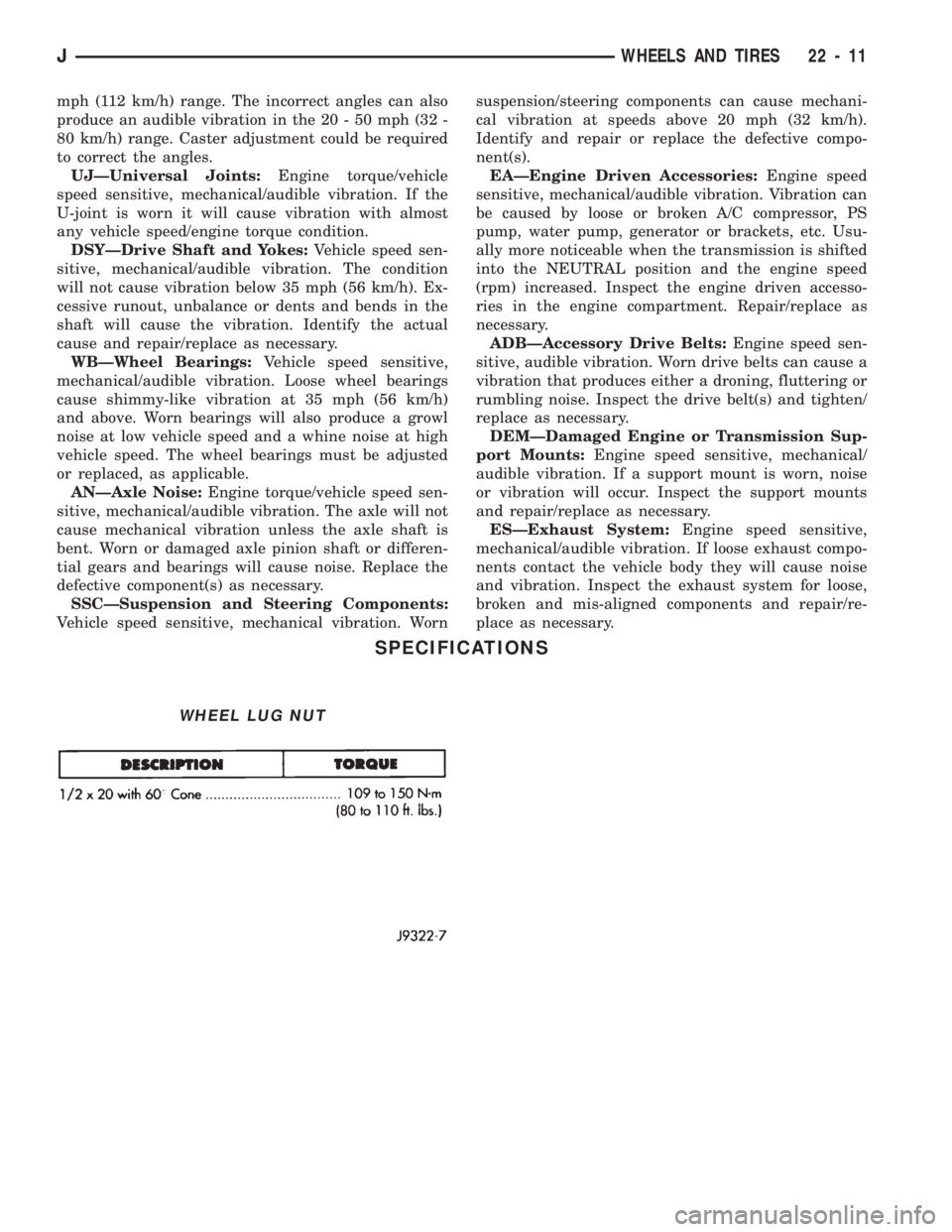
SPECIFICATIONS
WHEEL LUG NUT
JWHEELS AND TIRES 22 - 11
Page 1460 of 1784
INSTALLATION
(1) Place the grille opening panel (GOP) on bumper
and connect all front lamp wire harness connectors.
(2) Position the grille opening panel (GOP) on the
vehicle and install the side and upper nuts. Tighten
nuts to 7 Nzm (58 in-lbs) torque.
(3) Install the screw to attach grille opening panel
(GOP) to the crossmember support bracket. Tighten
the screw to 1 Nzm (11 in-lbs) torque.
(4) Install headlamps and park/turn signal lamps
in GOP.(5) Install the headlamp bezels on the GOP.
Tighten the screws to 1 Nzm (13 in-lbs) torque.
(6) Install the side marker lenses and screws on
the grille opening panel (GOP). Tighten the screws to
1Nzm (13 in-lbs) torque.
(7) Install the grille on the GOP. Tighten screws to
1Nzm (13 in-lbs) torque.
(8) Adjust the headlamp aim, if necessary. Refer to
the headlamp beam adjustment procedure within
Group 8L.
RADIATOR SUPPORT CROSSMEMBER
REMOVAL
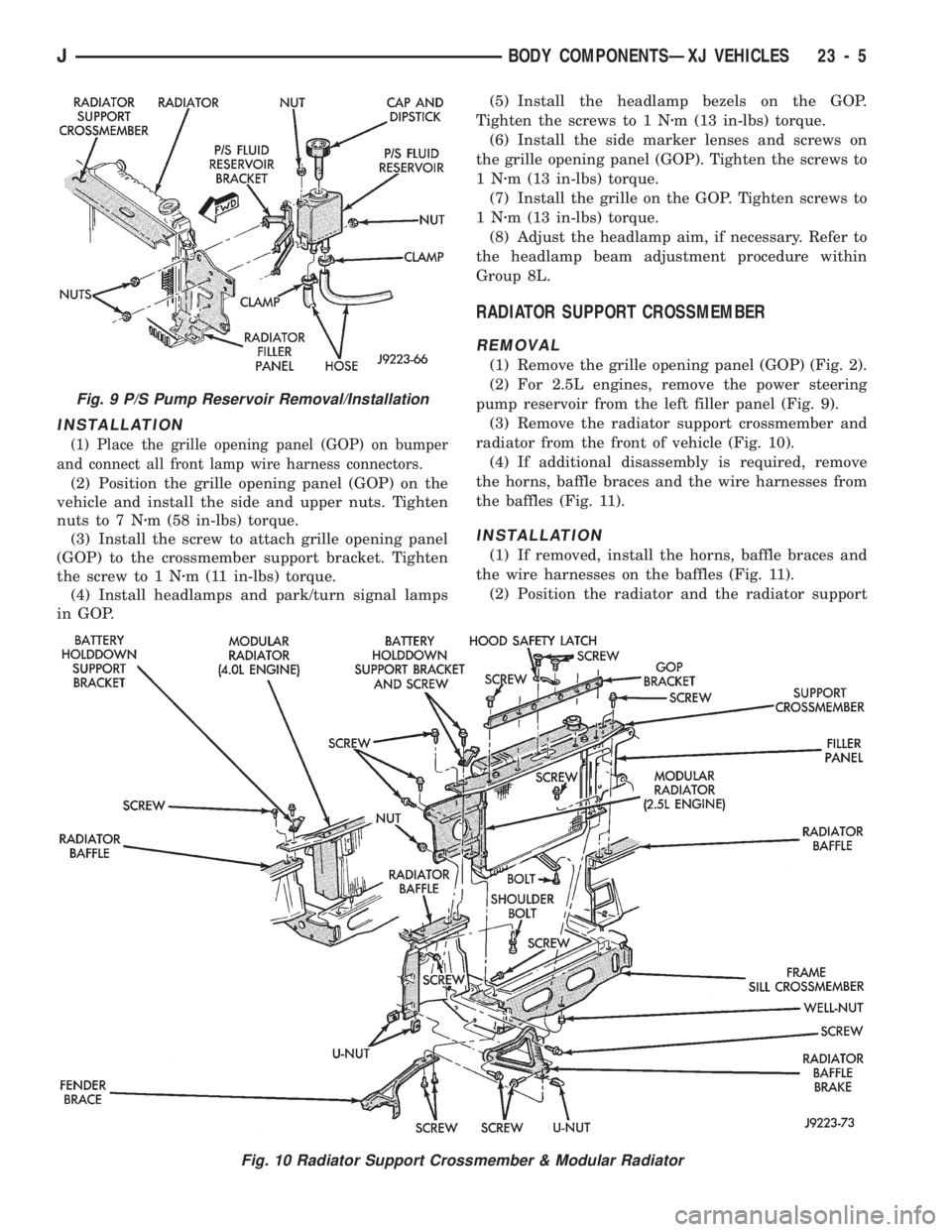
(1) Remove the grille opening panel (GOP) (Fig. 2).
(2) For 2.5L engines, remove the power steering
pump reservoir from the left filler panel (Fig. 9).
(3) Remove the radiator support crossmember and
radiator from the front of vehicle (Fig. 10).
(4) If additional disassembly is required, remove
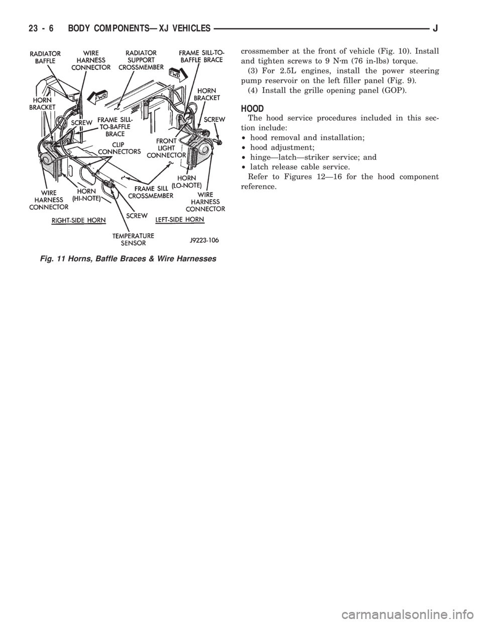
the horns, baffle braces and the wire harnesses from
the baffles (Fig. 11).
INSTALLATION
(1) If removed, install the horns, baffle braces and
the wire harnesses on the baffles (Fig. 11).
(2) Position the radiator and the radiator support
Fig. 9 P/S Pump Reservoir Removal/Installation
Fig. 10 Radiator Support Crossmember & Modular Radiator
JBODY COMPONENTSÐXJ VEHICLES 23 - 5
Page 1461 of 1784
crossmember at the front of vehicle (Fig. 10). Install
and tighten screws to 9 Nzm (76 in-lbs) torque.
(3) For 2.5L engines, install the power steering
pump reservoir on the left filler panel (Fig. 9).
(4) Install the grille opening panel (GOP).
HOOD
The hood service procedures included in this sec-
tion include:
²hood removal and installation;
²hood adjustment;
²hingeÐlatchÐstriker service; and
²latch release cable service.
Refer to Figures 12Ð16 for the hood component
reference.
Fig. 11 Horns, Baffle Braces & Wire Harnesses
23 - 6 BODY COMPONENTSÐXJ VEHICLESJ
Page 1465 of 1784
(2) Install the hinge nuts on the studs. Tighten the
restraint cable nut to 4 Nzm (38 in-lbs) torque.
Tighten the remaining nuts to 9 Nzm (77 in-lbs)
torque.
If a replacement hinge seal is being installed,
position it around the hinge arm, force it
against the hinge base.
(3) Position the hinge seal around the hinge arm
and on hinge base.
(4) Install the hood.
(5) Adjust the hood as necessary.
HOOD LATCH REPLACEMENT
REMOVAL
(1) Remove the screw that attaches the latch to the
hood inner panel (Fig. 15).
(2) Disconnect the latch from the hood and latch
connecting rod. Remove the latch from the hood.
INSTALLATION
(1) Connect the latch to the latch connecting rod
and position it on the hood inner panel.
(2) Install the screw that attaches the latch to the
hood inner panel.
(3) Tighten the screw to 9 Nzm (77 in-lbs) torque.
(4) Test the operation of the latch release cable and
latch.
HOOD LATCH STRIKER REPLACEMENT
REMOVE
(1) Remove the grille opening panel (GOP).
(2) Remove the screws that attach the striker to
the radiator baffle (Fig. 19).
(3) Remove the striker and shims from the baffle.
INSTALLATION
(1) Position the shims and striker on the radiator
baffle and install the screws.
(2) Tighten the screws to 21 Nzm (15 ft-lbs) torque.
(3) Test the striker/hood alignment by opening and
closing the hood several times. Adjust the striker, if
necessary.
LATCH RELEASE CABLE REPLACEMENT
REMOVAL
(1) Drill out the bellcrank to hood rivet heads and
remove the rivets (Fig. 14).
(2) Disconnect the bellcrank from the latch rod and
the latch release cable. Remove the bellcrank from
the hood.
(3) Disconnect the latch release cable from the
clips on the hood.
(4) Remove the left cowl side trim panel.
(5) Remove the cable bracket screws from the cowl
side panel.(6) Pull the cable through the dash panel and re-
move it from under the instrument panel.
INSTALLATION
(1) Insert the replacement cable end through the
hole in the dash panel into the engine compartment.
(2) Pull the cable forward and seat the grommet in
the dash panel.
(3) Position the cable bracket on the cowl side
panel and install the screws. Tighten the screws to
13 Nzm (111 in-lbs) torque.
(4) Install the left cowl side trim panel.
(5) Connect the cable and latch rod to the
bellcrank (Fig. 14).
(6) Position the bellcrank on the hood and install
the rivets.
(7) Attach the cable to the clips.
(8) Test release the cable for proper operation.
SAFETY LATCH STRIKER REPLACEMENT
REMOVAL
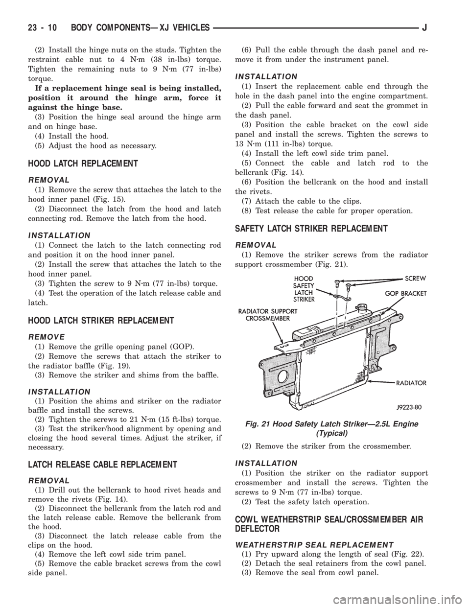
(1) Remove the striker screws from the radiator
support crossmember (Fig. 21).
(2) Remove the striker from the crossmember.
INSTALLATION
(1) Position the striker on the radiator support
crossmember and install the screws. Tighten the
screws to 9 Nzm (77 in-lbs) torque.
(2) Test the safety latch operation.
COWL WEATHERSTRIP SEAL/CROSSMEMBER AIR
DEFLECTOR
WEATHERSTRIP SEAL REPLACEMENT
(1) Pry upward along the length of seal (Fig. 22).
(2) Detach the seal retainers from the cowl panel.
(3) Remove the seal from cowl panel.
Fig. 21 Hood Safety Latch StrikerÐ2.5L Engine
(Typical)
23 - 10 BODY COMPONENTSÐXJ VEHICLESJ
Page 1466 of 1784
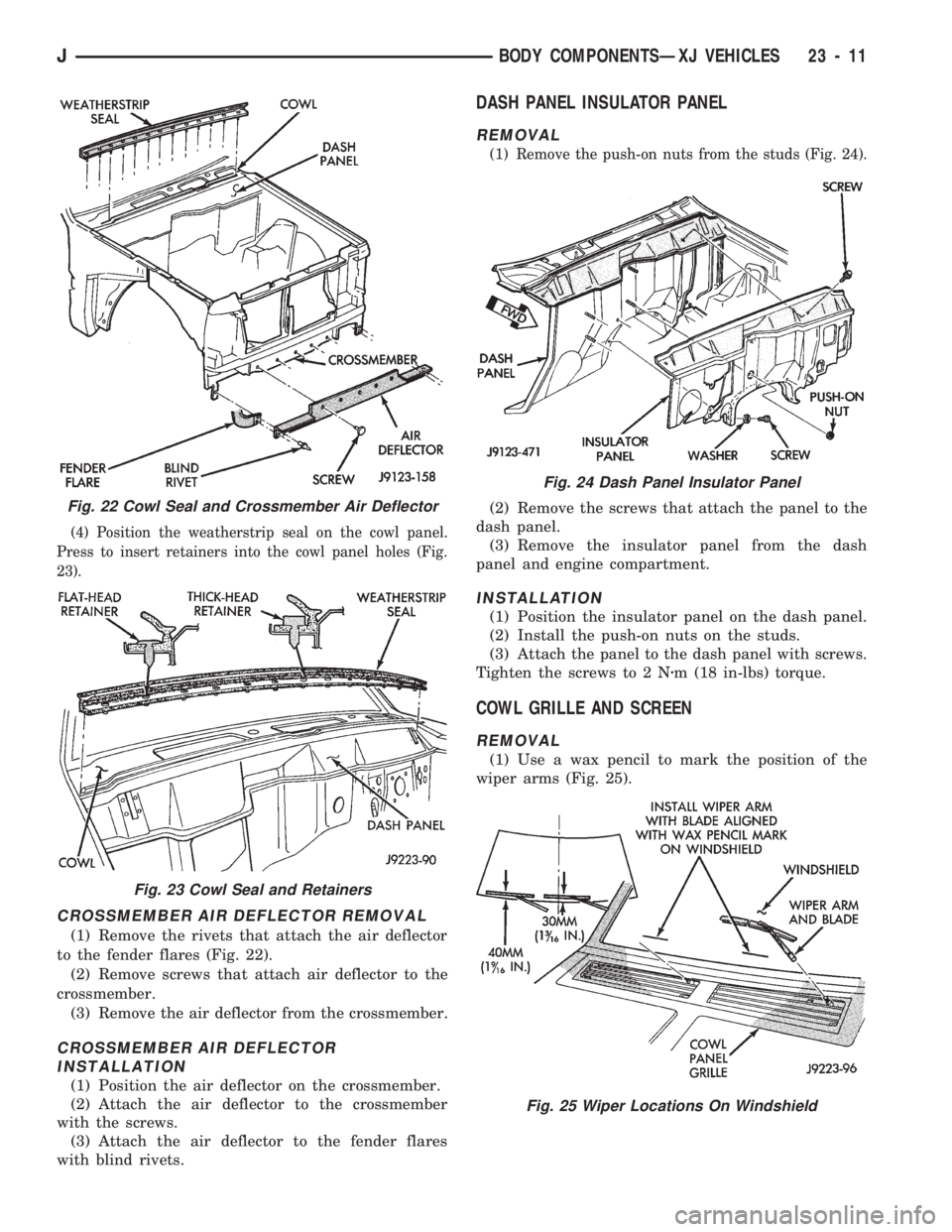
(4) Position the weatherstrip seal on the cowl panel.
Press to insert retainers into the cowl panel holes (Fig.
23).
CROSSMEMBER AIR DEFLECTOR REMOVAL
(1) Remove the rivets that attach the air deflector
to the fender flares (Fig. 22).
(2) Remove screws that attach air deflector to the
crossmember.
(3) Remove the air deflector from the crossmember.
CROSSMEMBER AIR DEFLECTOR
INSTALLATION
(1) Position the air deflector on the crossmember.
(2) Attach the air deflector to the crossmember
with the screws.
(3) Attach the air deflector to the fender flares
with blind rivets.
DASH PANEL INSULATOR PANEL
REMOVAL
(1) Remove the push-on nuts from the studs (Fig. 24).
(2) Remove the screws that attach the panel to the
dash panel.
(3) Remove the insulator panel from the dash
panel and engine compartment.
INSTALLATION
(1) Position the insulator panel on the dash panel.
(2) Install the push-on nuts on the studs.
(3) Attach the panel to the dash panel with screws.
Tighten the screws to 2 Nzm (18 in-lbs) torque.
COWL GRILLE AND SCREEN
REMOVAL
(1) Use a wax pencil to mark the position of the
wiper arms (Fig. 25).
Fig. 22 Cowl Seal and Crossmember Air Deflector
Fig. 23 Cowl Seal and Retainers
Fig. 24 Dash Panel Insulator Panel
Fig. 25 Wiper Locations On Windshield
JBODY COMPONENTSÐXJ VEHICLES 23 - 11