1994 JEEP CHEROKEE engine
[x] Cancel search: enginePage 1719 of 1784
EMISSION CONTROL SYSTEMS
CONTENTS
page page
COMPONENT REMOVAL/INSTALLATION...... 8
EVAPORATIVE EMISSION CONTROLS....... 4EXHAUST EMISSION CONTROLS........... 7
GENERAL INFORMATION.................. 1
GENERAL INFORMATION
INDEX
page page
DRB Scan Tool........................... 2
Service Reminder Indicator (SRI) Lamp......... 1Vacuum Hose Routing Schematics............ 1
Vehicle Emission Control Information (VECI) Label . 1
SERVICE REMINDER INDICATOR (SRI) LAMP
The instrument panel mounted SRI lamp was for-
merly referred to as the emission maintenance re-
minder (EMR) lamp. It isnot usedon any Jeep
model for the 1994 model year.
VEHICLE EMISSION CONTROL INFORMATION
(VECI) LABEL
All vehicles are equipped with a combined VECI
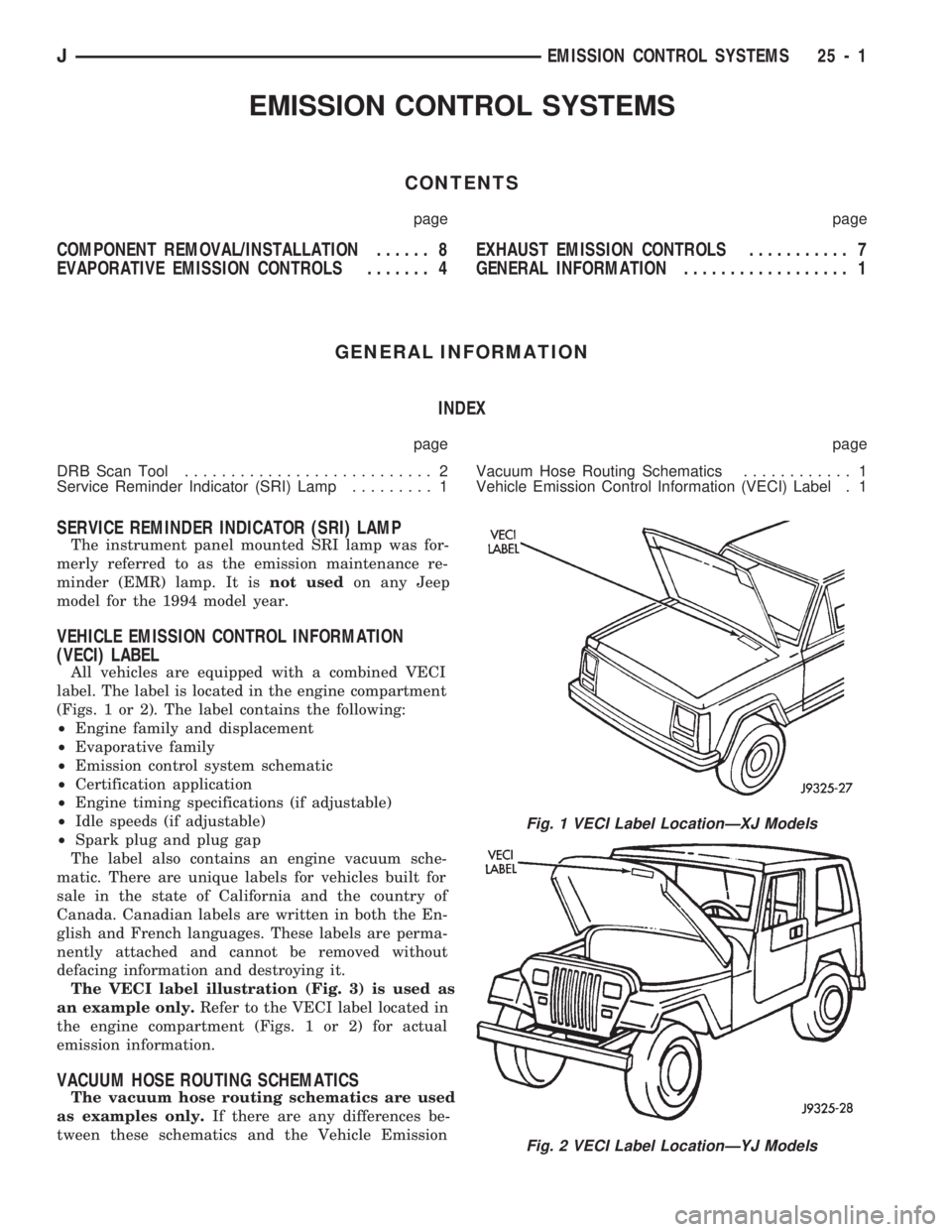
label. The label is located in the engine compartment
(Figs. 1 or 2). The label contains the following:
²Engine family and displacement
²Evaporative family
²Emission control system schematic
²Certification application
²Engine timing specifications (if adjustable)
²Idle speeds (if adjustable)
²Spark plug and plug gap
The label also contains an engine vacuum sche-
matic. There are unique labels for vehicles built for
sale in the state of California and the country of
Canada. Canadian labels are written in both the En-
glish and French languages. These labels are perma-
nently attached and cannot be removed without
defacing information and destroying it.
The VECI label illustration (Fig. 3) is used as
an example only.Refer to the VECI label located in
the engine compartment (Figs. 1 or 2) for actual
emission information.
VACUUM HOSE ROUTING SCHEMATICS
The vacuum hose routing schematics are used
as examples only.If there are any differences be-
tween these schematics and the Vehicle Emission
Fig. 1 VECI Label LocationÐXJ Models
Fig. 2 VECI Label LocationÐYJ Models
JEMISSION CONTROL SYSTEMS 25 - 1
Page 1720 of 1784
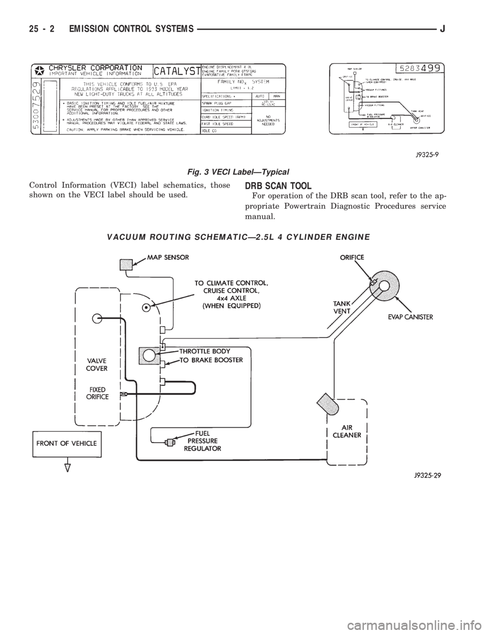
Control Information (VECI) label schematics, those
shown on the VECI label should be used.DRB SCAN TOOL
For operation of the DRB scan tool, refer to the ap-
propriate Powertrain Diagnostic Procedures service
manual.
VACUUM ROUTING SCHEMATICÐ2.5L 4 CYLINDER ENGINE
Fig. 3 VECI LabelÐTypical
25 - 2 EMISSION CONTROL SYSTEMSJ
Page 1721 of 1784
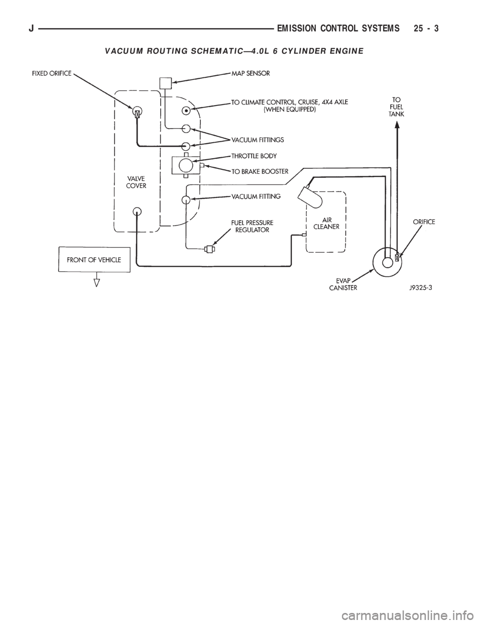
VACUUM ROUTING SCHEMATICÐ4.0L 6 CYLINDER ENGINE
JEMISSION CONTROL SYSTEMS 25 - 3
Page 1722 of 1784
EVAPORATIVE EMISSION CONTROLS
INDEX
page page
Crankcase Ventilation System................ 5
EVAP (Evaporation) Control System........... 4
EVAP Canister........................... 4Fuel Tank Filler Tube Cap.................. 4
Pressure Relief/Rollover Valve................ 5
EVAP (EVAPORATION) CONTROL SYSTEM
GENERAL INFORMATION
The function of the EVAP control system is to pre-
vent the emissions of gasoline vapors from the fuel
tank into the atmosphere. When fuel evaporates in
the fuel tank, the vapors pass through vent hoses or
tubes to a carbon filled EVAP canister. They are
temporarily held in the canister until they can be
drawn into the intake manifold when the engine is
running.
The EVAP canister is a feature on all models for
the storage of fuel vapors from the fuel tank.
The hoses used in this system are specially
manufactured. If replacement becomes neces-
sary, it is important to use only fuel resistant
hose.
EVAP CANISTER
A sealed, maintenance free, EVAP canister is used
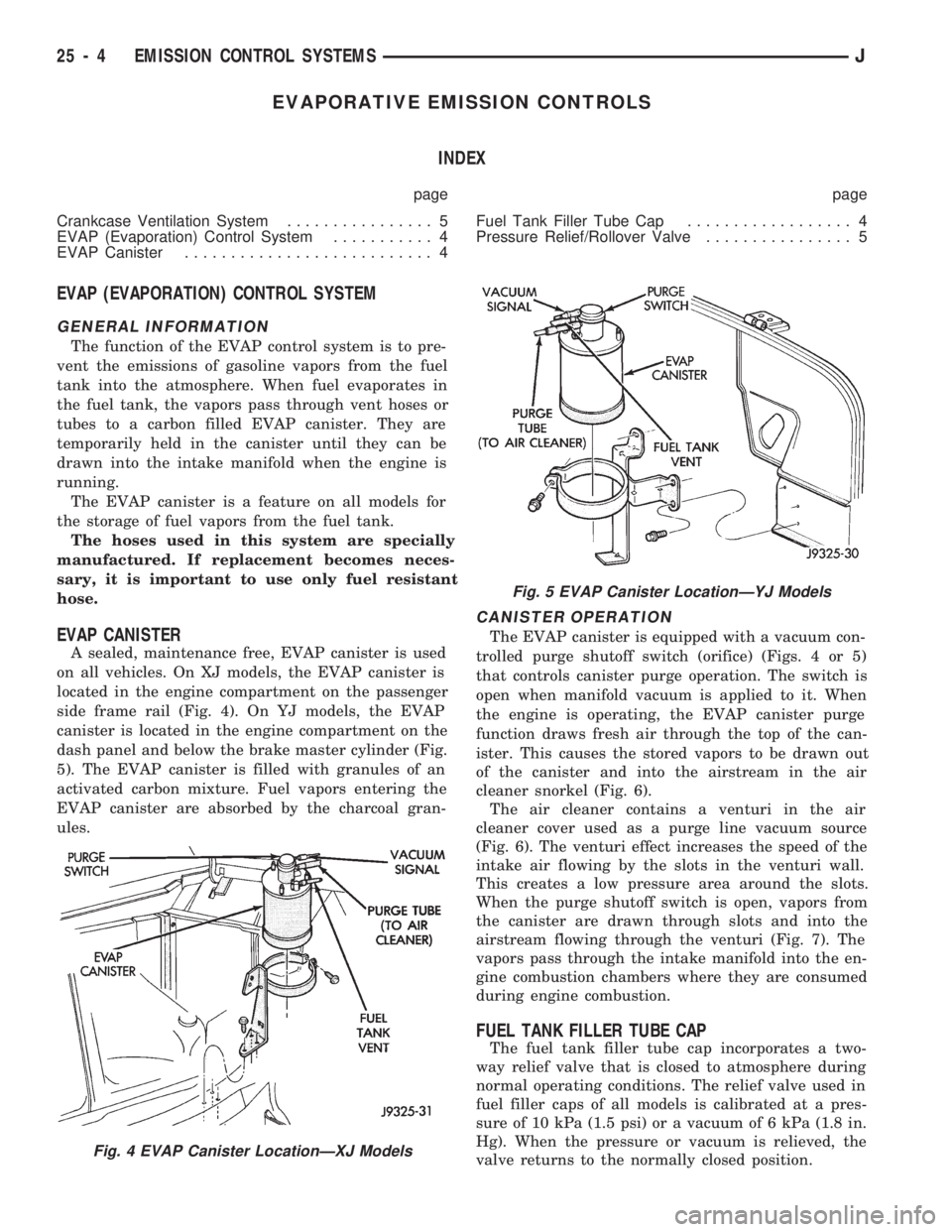
on all vehicles. On XJ models, the EVAP canister is
located in the engine compartment on the passenger
side frame rail (Fig. 4). On YJ models, the EVAP
canister is located in the engine compartment on the
dash panel and below the brake master cylinder (Fig.
5). The EVAP canister is filled with granules of an
activated carbon mixture. Fuel vapors entering the
EVAP canister are absorbed by the charcoal gran-
ules.
CANISTER OPERATION
The EVAP canister is equipped with a vacuum con-
trolled purge shutoff switch (orifice) (Figs. 4 or 5)
that controls canister purge operation. The switch is
open when manifold vacuum is applied to it. When
the engine is operating, the EVAP canister purge
function draws fresh air through the top of the can-
ister. This causes the stored vapors to be drawn out
of the canister and into the airstream in the air
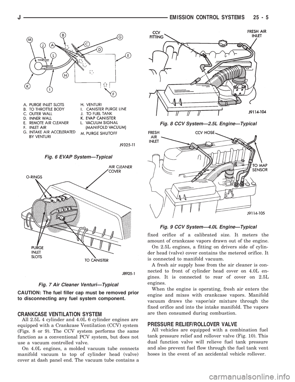
cleaner snorkel (Fig. 6).
The air cleaner contains a venturi in the air
cleaner cover used as a purge line vacuum source
(Fig. 6). The venturi effect increases the speed of the
intake air flowing by the slots in the venturi wall.
This creates a low pressure area around the slots.
When the purge shutoff switch is open, vapors from
the canister are drawn through slots and into the
airstream flowing through the venturi (Fig. 7). The
vapors pass through the intake manifold into the en-
gine combustion chambers where they are consumed
during engine combustion.
FUEL TANK FILLER TUBE CAP
The fuel tank filler tube cap incorporates a two-
way relief valve that is closed to atmosphere during
normal operating conditions. The relief valve used in
fuel filler caps of all models is calibrated at a pres-
sure of 10 kPa (1.5 psi) or a vacuum of 6 kPa (1.8 in.
Hg). When the pressure or vacuum is relieved, the
valve returns to the normally closed position.
Fig. 4 EVAP Canister LocationÐXJ Models
Fig. 5 EVAP Canister LocationÐYJ Models
25 - 4 EMISSION CONTROL SYSTEMSJ
Page 1723 of 1784
CAUTION: The fuel filler cap must be removed prior
to disconnecting any fuel system component.
CRANKCASE VENTILATION SYSTEM
All 2.5L 4 cylinder and 4.0L 6 cylinder engines are
equipped with a Crankcase Ventilation (CCV) system
(Figs. 8 or 9). The CCV system performs the same
function as a conventional PCV system, but does not
use a vacuum controlled valve.
On 4.0L engines, a molded vacuum tube connects
manifold vacuum to top of cylinder head (valve)
cover at dash panel end. The vacuum tube contains afixed orifice of a calibrated size. It meters the
amount of crankcase vapors drawn out of the engine.
On 2.5L engines, a fitting on drivers side of cylin-
der head (valve) cover contains the metered orifice. It
is connected to manifold vacuum.
A fresh air supply hose from the air cleaner is con-
nected to front of cylinder head cover on 4.0L en-
gines. It is connected to rear of cover on 2.5L
engines.
When the engine is operating, fresh air enters the
engine and mixes with crankcase vapors. Manifold
vacuum draws the vapor/air mixture through the
fixed orifice and into the intake manifold. The vapors
are then consumed during combustion.
PRESSURE RELIEF/ROLLOVER VALVE
All vehicles are equipped with a combination fuel
tank pressure relief and rollover valve (Fig. 10). This
dual function valve will relieve fuel tank pressure
and also prevent fuel flow through the fuel tank vent
hoses in the event of an accidental vehicle rollover.
Fig. 6 EVAP SystemÐTypical
Fig. 7 Air Cleaner VenturiÐTypical
Fig. 8 CCV SystemÐ2.5L EngineÐTypical
Fig. 9 CCV SystemÐ4.0L EngineÐTypical
JEMISSION CONTROL SYSTEMS 25 - 5
Page 1725 of 1784
EXHAUST EMISSION CONTROLS
INDEX
page page
Air Cleaner.............................. 7Oxygen (O2S) Sensor...................... 7
AIR CLEANER
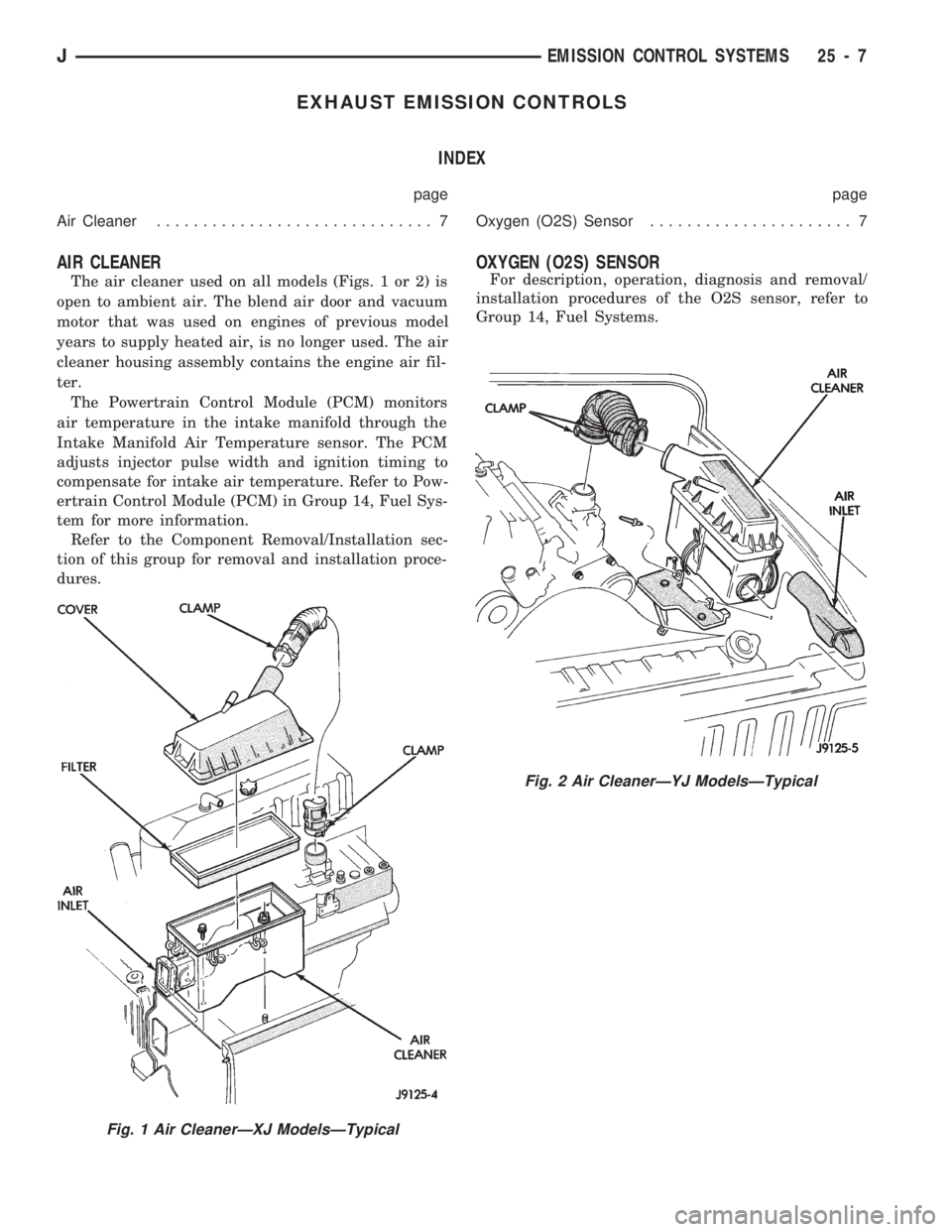
The air cleaner used on all models (Figs. 1 or 2) is
open to ambient air. The blend air door and vacuum
motor that was used on engines of previous model
years to supply heated air, is no longer used. The air
cleaner housing assembly contains the engine air fil-
ter.
The Powertrain Control Module (PCM) monitors
air temperature in the intake manifold through the
Intake Manifold Air Temperature sensor. The PCM
adjusts injector pulse width and ignition timing to
compensate for intake air temperature. Refer to Pow-
ertrain Control Module (PCM) in Group 14, Fuel Sys-
tem for more information.
Refer to the Component Removal/Installation sec-
tion of this group for removal and installation proce-
dures.
OXYGEN (O2S) SENSOR
For description, operation, diagnosis and removal/
installation procedures of the O2S sensor, refer to
Group 14, Fuel Systems.
Fig. 2 Air CleanerÐYJ ModelsÐTypical
Fig. 1 Air CleanerÐXJ ModelsÐTypical
JEMISSION CONTROL SYSTEMS 25 - 7
Page 1727 of 1784
Install air filter and cover.
(3) Install vacuum lines to housing.
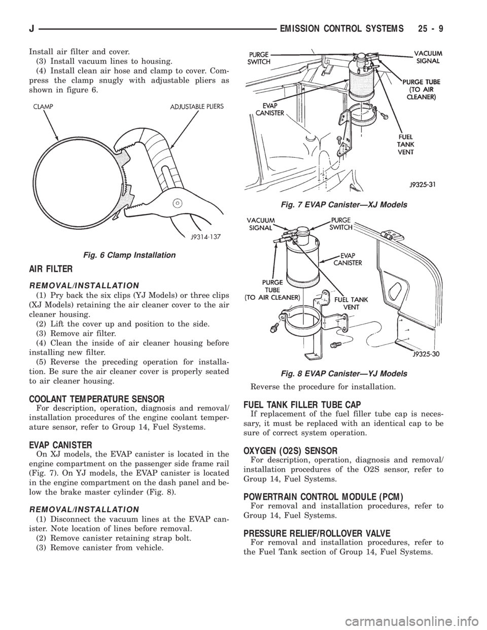
(4) Install clean air hose and clamp to cover. Com-
press the clamp snugly with adjustable pliers as
shown in figure 6.
AIR FILTER
REMOVAL/INSTALLATION
(1) Pry back the six clips (YJ Models) or three clips
(XJ Models) retaining the air cleaner cover to the air
cleaner housing.
(2) Lift the cover up and position to the side.
(3) Remove air filter.
(4) Clean the inside of air cleaner housing before
installing new filter.
(5) Reverse the preceding operation for installa-
tion. Be sure the air cleaner cover is properly seated
to air cleaner housing.
COOLANT TEMPERATURE SENSOR
For description, operation, diagnosis and removal/
installation procedures of the engine coolant temper-
ature sensor, refer to Group 14, Fuel Systems.
EVAP CANISTER
On XJ models, the EVAP canister is located in the
engine compartment on the passenger side frame rail
(Fig. 7). On YJ models, the EVAP canister is located
in the engine compartment on the dash panel and be-
low the brake master cylinder (Fig. 8).
REMOVAL/INSTALLATION
(1) Disconnect the vacuum lines at the EVAP can-
ister. Note location of lines before removal.
(2) Remove canister retaining strap bolt.
(3) Remove canister from vehicle.Reverse the procedure for installation.
FUEL TANK FILLER TUBE CAP
If replacement of the fuel filler tube cap is neces-
sary, it must be replaced with an identical cap to be
sure of correct system operation.
OXYGEN (O2S) SENSOR
For description, operation, diagnosis and removal/
installation procedures of the O2S sensor, refer to
Group 14, Fuel Systems.
POWERTRAIN CONTROL MODULE (PCM)
For removal and installation procedures, refer to
Group 14, Fuel Systems.
PRESSURE RELIEF/ROLLOVER VALVE
For removal and installation procedures, refer to
the Fuel Tank section of Group 14, Fuel Systems.
Fig. 7 EVAP CanisterÐXJ Models
Fig. 8 EVAP CanisterÐYJ Models
Fig. 6 Clamp Installation
JEMISSION CONTROL SYSTEMS 25 - 9
Page 1730 of 1784
FOREWORD
The information contained in this service manual has been prepared for the professional automotive tech-
nician involved in daily repair operations. This manual does not cover theory of operation, which is addressed
in service training material. Information describing the operation and use of standard and optional equipment
is included in the Owner 's Manual provided with the vehicle.
Information in this manual is divided into groups. These groups contain general information, diagnosis,
testing, adjustments, removal, installation, disassembly, and assembly procedures for the components. To as-
sist in locating a group title page, use the Group Tab Locator on the following page. The solid bar after the
group title is aligned to a solid tab on the first page of each group. The first page of the group has a contents
section that lists major topics within the group. If you are not sure which Group contains the information you
need, look up the Component/System in the alphabetical index located in the rear of this manual.
A Service Manual Comment form is included at the rear of this manual. Use the form to provide Chrysler
Corporation with your comments and suggestions.
Tightening torques are provided as a specific value throughout this manual. This value represents the
midpoint of the acceptable engineering torque range for a given fastener application. These torque values are
intended for use in service assembly and installation procedures using the correct OEM fasteners. When re-
placing fasteners, always use the same type (part number) fastener as removed.
Chrysler Corporation reserves the right to change testing procedures, specifications, diagnosis, repair
methods, or vehicle wiring at any time without prior notice or incurring obligation.
NOTE: The acronyms, terminology and nomenclature used to identify emissions related components in
this manual may have changed from prior publications. These new terms are in compliance with S.A.E.
recommended practice J1930.
NEXT PAGE©