Page 1407 of 1784

SHIFT LINKAGE ADJUSTMENT
(1) Remove shift lever bezel.
(2) Move shift lever into 4L position.
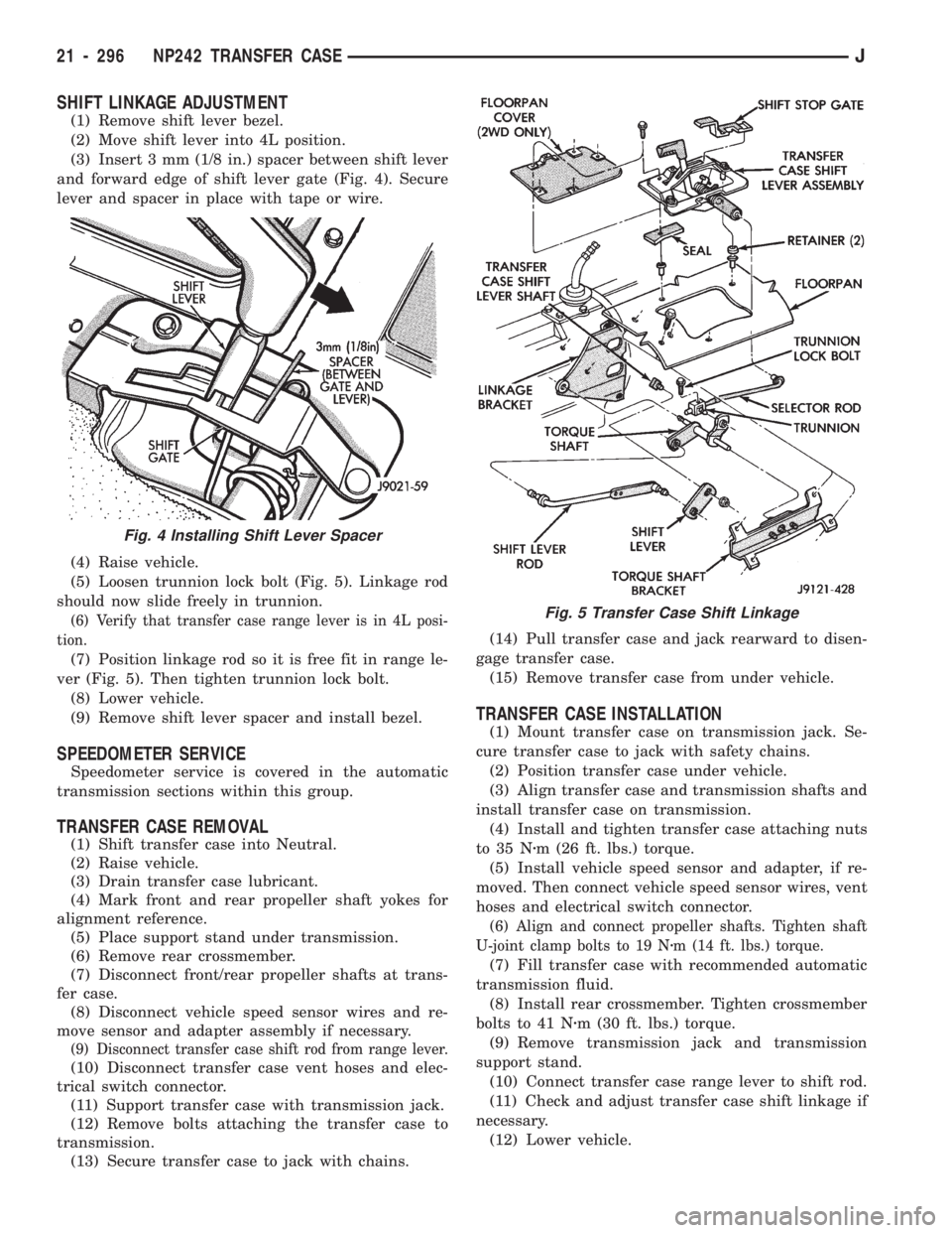
(3) Insert 3 mm (1/8 in.) spacer between shift lever
and forward edge of shift lever gate (Fig. 4). Secure
lever and spacer in place with tape or wire.
(4) Raise vehicle.
(5) Loosen trunnion lock bolt (Fig. 5). Linkage rod
should now slide freely in trunnion.
(6) Verify that transfer case range lever is in 4L posi-
tion.
(7) Position linkage rod so it is free fit in range le-
ver (Fig. 5). Then tighten trunnion lock bolt.
(8) Lower vehicle.
(9) Remove shift lever spacer and install bezel.
SPEEDOMETER SERVICE
Speedometer service is covered in the automatic
transmission sections within this group.
TRANSFER CASE REMOVAL
(1) Shift transfer case into Neutral.
(2) Raise vehicle.
(3) Drain transfer case lubricant.
(4) Mark front and rear propeller shaft yokes for
alignment reference.
(5) Place support stand under transmission.
(6) Remove rear crossmember.
(7) Disconnect front/rear propeller shafts at trans-
fer case.
(8) Disconnect vehicle speed sensor wires and re-
move sensor and adapter assembly if necessary.
(9) Disconnect transfer case shift rod from range lever.
(10) Disconnect transfer case vent hoses and elec-
trical switch connector.
(11) Support transfer case with transmission jack.
(12) Remove bolts attaching the transfer case to
transmission.
(13) Secure transfer case to jack with chains.(14) Pull transfer case and jack rearward to disen-
gage transfer case.
(15) Remove transfer case from under vehicle.
TRANSFER CASE INSTALLATION
(1) Mount transfer case on transmission jack. Se-
cure transfer case to jack with safety chains.
(2) Position transfer case under vehicle.
(3) Align transfer case and transmission shafts and
install transfer case on transmission.
(4) Install and tighten transfer case attaching nuts
to 35 Nzm (26 ft. lbs.) torque.
(5) Install vehicle speed sensor and adapter, if re-
moved. Then connect vehicle speed sensor wires, vent
hoses and electrical switch connector.
(6) Align and connect propeller shafts. Tighten shaft
U-joint clamp bolts to 19 Nzm (14 ft. lbs.) torque.
(7) Fill transfer case with recommended automatic
transmission fluid.
(8) Install rear crossmember. Tighten crossmember
bolts to 41 Nzm (30 ft. lbs.) torque.
(9) Remove transmission jack and transmission
support stand.
(10) Connect transfer case range lever to shift rod.
(11) Check and adjust transfer case shift linkage if
necessary.
(12) Lower vehicle.
Fig. 4 Installing Shift Lever Spacer
Fig. 5 Transfer Case Shift Linkage
21 - 296 NP242 TRANSFER CASEJ
Page 1417 of 1784

Inspect the differential gears, thrust washers and
case halves. Replace the mainshaft gear if the gear
teeth or the brass ring on the underside of the gear
are damaged. Replace the differential as an assembly
if the gears, case halves, or the pins in the lower case
half are damaged.
Inspect the case halves, extension housing and re-
tainers for cracks, porosity, or damaged sealing sur-
faces. Inspect the shafts, gears, chain and shift
components for wear or damage.
Inspect all of the transfer case bearings for wear,
roughness, pitting, or galling. Replace worn or dam-
aged bearings as outlined in the assembly section.
TRANSFER CASE ASSEMBLY
(1) Lubricate the transfer case components with
automatic transmission fluid or petroleum jelly
(where indicated) during assembly.
CAUTION: The bearing bores in various transfer
case components contain oil feed holes. Be sure re-
placement bearings do not block these feed holes.
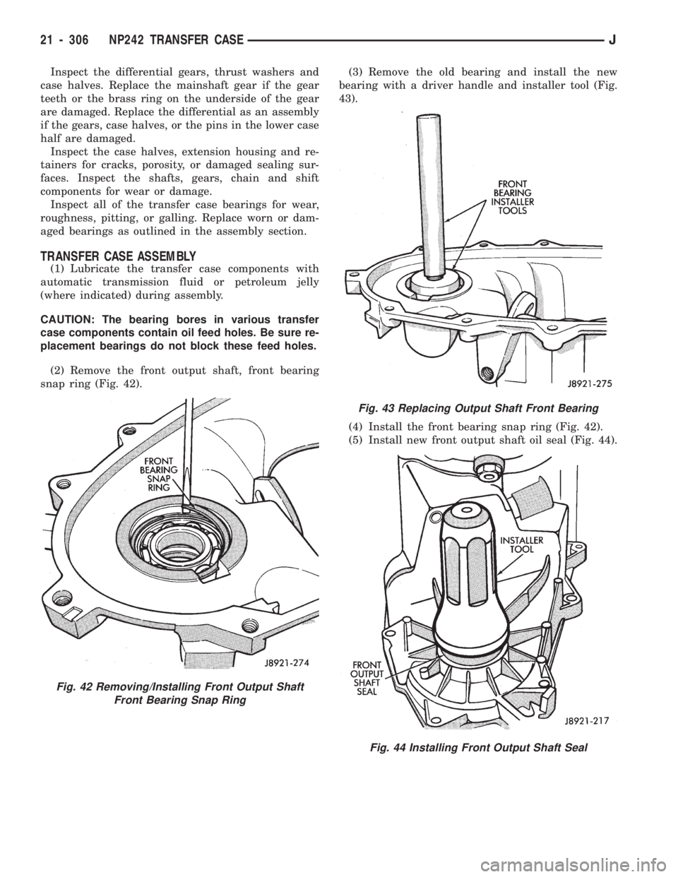
(2) Remove the front output shaft, front bearing
snap ring (Fig. 42).(3) Remove the old bearing and install the new
bearing with a driver handle and installer tool (Fig.
43).
(4) Install the front bearing snap ring (Fig. 42).
(5) Install new front output shaft oil seal (Fig. 44).
Fig. 42 Removing/Installing Front Output Shaft
Front Bearing Snap Ring
Fig. 43 Replacing Output Shaft Front Bearing
Fig. 44 Installing Front Output Shaft Seal
21 - 306 NP242 TRANSFER CASEJ
Page 1419 of 1784
(11) Assemble low range gear, input gear thrust
washers, input gear and input gear retainer (Fig. 49).
(12) Install low range gear snap ring (Fig. 50).
(13) Lubricate input gear and low range gears with
automatic transmission fluid.
(14) Start the input gear shaft into the front case
bearing.
(15) Press the input gear shaft into the front bear-
ing.CAUTION: Be sure the input gear installer tool is
the proper size. The wrong size tool could push the
input gear pilot bearing too far into the gear bore
(Fig. 51). Also, do not press against the end sur-
faces of the low range gear. The gear case and
thrust washers could be damaged.
(16) Install new input gear snap ring (Fig. 52).
Fig. 49 Low Range And Input Gear Assembly
Fig. 50 Install Low Range Gear Snap Ring
Fig. 51 Input Gear Installation
Fig. 52 Install Input Gear Snap Ring
21 - 308 NP242 TRANSFER CASEJ
Page 1421 of 1784
(24) Position low range fork and hub in case. Be
sure low range fork pin is engaged in the shift sector
slot (Fig. 57).
(25) Lubricate differential components with auto-
matic transmission fluid.
(26) Install sprocket gear in differential bottom
case (Fig. 58).(27) Install differential planet gears and new
thrust washers (Fig. 59).Be sure thrust washers
are installed at top and bottom of each planet
gear.
(28) Install differential mainshaft gear (Fig. 59).
(29) Align and position differential top case on bot-
tom case (Fig. 60). Align using scribe marks made at
disassembly.
(30) Install and tighten the differential case bolts
to specified torque.
Fig. 57 Positioning Low Range Fork
Fig. 58 Installing Differential Sprocket Gear
Fig. 59 Installing Mainshaft And Planet Gears
Fig. 60 Differential Case Assembly
21 - 310 NP242 TRANSFER CASEJ
Page 1428 of 1784
(72) Apply 3 mm (1/8 in.) wide bead of Mopar gas-
ket maker, silicone adhesive sealer, or Loctite 518 to
seal surface of extension housing.
(73) Install extension housing on case. Tighten
housing bolts to 41 Nzm (30 ft. lbs.) torque.
(74) Install front yoke. Secure yoke with new seal
washer and nut. Tighten nut to 149 Nzm (110 ft. lbs.)
torque.
(75) Install new gasket on vacuum switch and in-
stall switch in the case. Tighten switch to 27 Nzm (20
ft. lbs.) torque.
(76) Install speedometer components (Fig. 85).
(77) Install and tighten drain plug to 47 Nzm (35
ft. lbs.) torque.
(78) After installing transfer case, refill with rec-
ommended transmission fluid.
(79) Tighten fill plug to 47 Nzm (35 ft. lbs.) torque.
(80) Adjust transfer case shift linkage.
Fig. 85 Speedometer Components
JNP242 TRANSFER CASE 21 - 317
Page 1431 of 1784
TRANSMISSION/TRANSFER CASE SPECIFICATIONS
TORQUE SPECIFICATIONSÐ
AX 15 MANUAL TRANSMISSION
21 - 320 TRANSMISSION/TRANSFER CASE SPECIFICATIONSJ
Page 1432 of 1784
SELECTIVE SNAP RING CHARTÐAX 15 MANUAL TRANSMISSION
JTRANSMISSION/TRANSFER CASE SPECIFICATIONS 21 - 321
Page 1433 of 1784
30RH/32RH GENERAL SPECIFICATIONS
30RH/32RH SNAP RING/THRUST WASHER/THRUST PLATE SPECIFICATIONS
21 - 322 TRANSMISSION/TRANSFER CASE SPECIFICATIONSJ