Page 1357 of 1784

(8) Press regulator valve sleeve into bore and in-
stall retainer (Fig. 5 and 6). Be sure retainer is posi-
tioned in sleeve lugs as shown.
(9) Install 1-2 shift valve, spring and plug (Fig. 4).
Then press valve assembly into bore and install re-
tainer.
(10) Install replacement O-rings on solenoids and
install solenoids on valve body. Tighten solenoid at-
taching bolts to 10 Nzm (7 ft-lbs) torque.
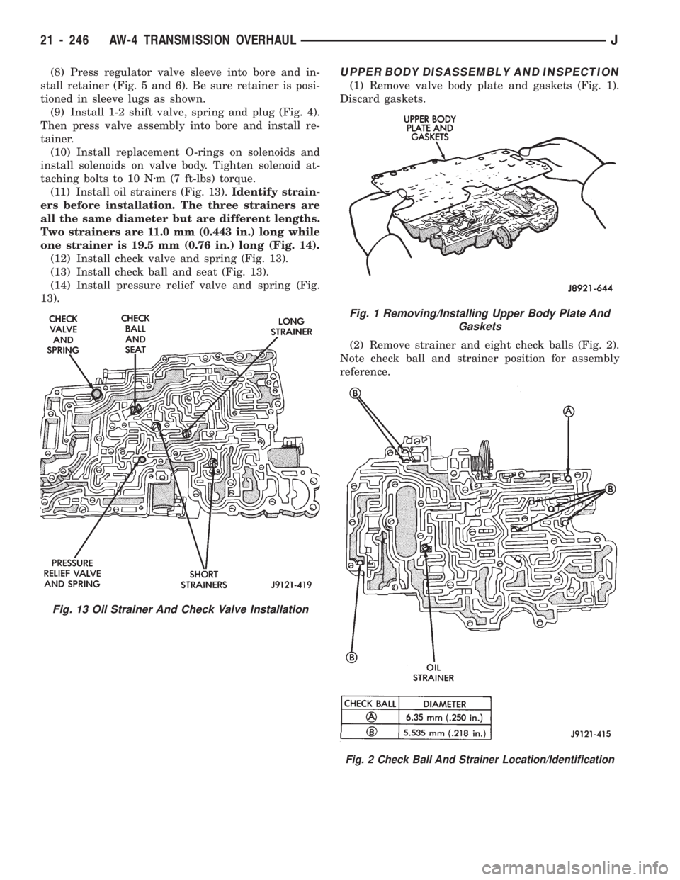
(11) Install oil strainers (Fig. 13).Identify strain-
ers before installation. The three strainers are
all the same diameter but are different lengths.
Two strainers are 11.0 mm (0.443 in.) long while
one strainer is 19.5 mm (0.76 in.) long (Fig. 14).
(12) Install check valve and spring (Fig. 13).
(13) Install check ball and seat (Fig. 13).
(14) Install pressure relief valve and spring (Fig.
13).UPPER BODY DISASSEMBLY AND INSPECTION
(1) Remove valve body plate and gaskets (Fig. 1).
Discard gaskets.
(2) Remove strainer and eight check balls (Fig. 2).
Note check ball and strainer position for assembly
reference.
Fig. 1 Removing/Installing Upper Body Plate And
Gaskets
Fig. 2 Check Ball And Strainer Location/Identification
Fig. 13 Oil Strainer And Check Valve Installation
21 - 246 AW-4 TRANSMISSION OVERHAULJ
Page 1358 of 1784

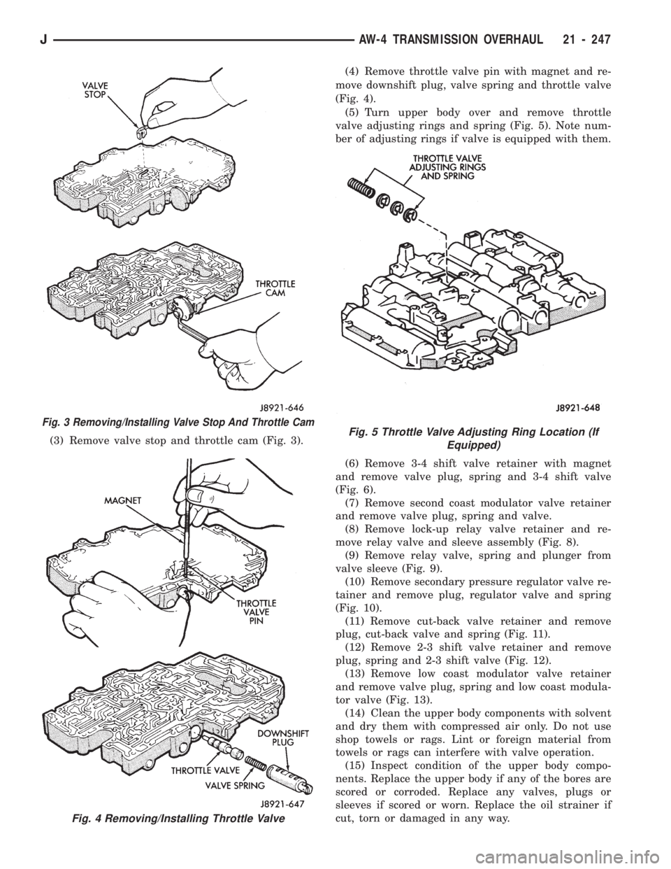
(3) Remove valve stop and throttle cam (Fig. 3).(4) Remove throttle valve pin with magnet and re-
move downshift plug, valve spring and throttle valve
(Fig. 4).
(5) Turn upper body over and remove throttle
valve adjusting rings and spring (Fig. 5). Note num-
ber of adjusting rings if valve is equipped with them.
(6) Remove 3-4 shift valve retainer with magnet
and remove valve plug, spring and 3-4 shift valve
(Fig. 6).
(7) Remove second coast modulator valve retainer
and remove valve plug, spring and valve.
(8) Remove lock-up relay valve retainer and re-
move relay valve and sleeve assembly (Fig. 8).
(9) Remove relay valve, spring and plunger from
valve sleeve (Fig. 9).
(10) Remove secondary pressure regulator valve re-
tainer and remove plug, regulator valve and spring
(Fig. 10).
(11) Remove cut-back valve retainer and remove
plug, cut-back valve and spring (Fig. 11).
(12) Remove 2-3 shift valve retainer and remove
plug, spring and 2-3 shift valve (Fig. 12).
(13) Remove low coast modulator valve retainer
and remove valve plug, spring and low coast modula-
tor valve (Fig. 13).
(14) Clean the upper body components with solvent
and dry them with compressed air only. Do not use
shop towels or rags. Lint or foreign material from
towels or rags can interfere with valve operation.
(15) Inspect condition of the upper body compo-
nents. Replace the upper body if any of the bores are
scored or corroded. Replace any valves, plugs or
sleeves if scored or worn. Replace the oil strainer if
cut, torn or damaged in any way.
Fig. 3 Removing/Installing Valve Stop And Throttle Cam
Fig. 4 Removing/Installing Throttle Valve
Fig. 5 Throttle Valve Adjusting Ring Location (If
Equipped)
JAW-4 TRANSMISSION OVERHAUL 21 - 247
Page 1359 of 1784
Fig. 6 Removing/Installing 3-4 Shift Valve
Fig. 7 Removing/Installing Second Coast Modulator
Valve
Fig. 8 Removing/Installing Converter Clutch Relay
Valve
Fig. 9 Relay Valve Components
21 - 248 AW-4 TRANSMISSION OVERHAULJ
Page 1360 of 1784
Fig. 10 Removing/Installing Secondary Pressure
Regulator Valve
Fig. 11 Removing/Installing Cut-Back Valve
Fig. 12 Removing/Installing 2-3 Shift Valve
Fig. 13 Removing/Installing Low Coast Modulator
Valve
JAW-4 TRANSMISSION OVERHAUL 21 - 249
Page 1361 of 1784

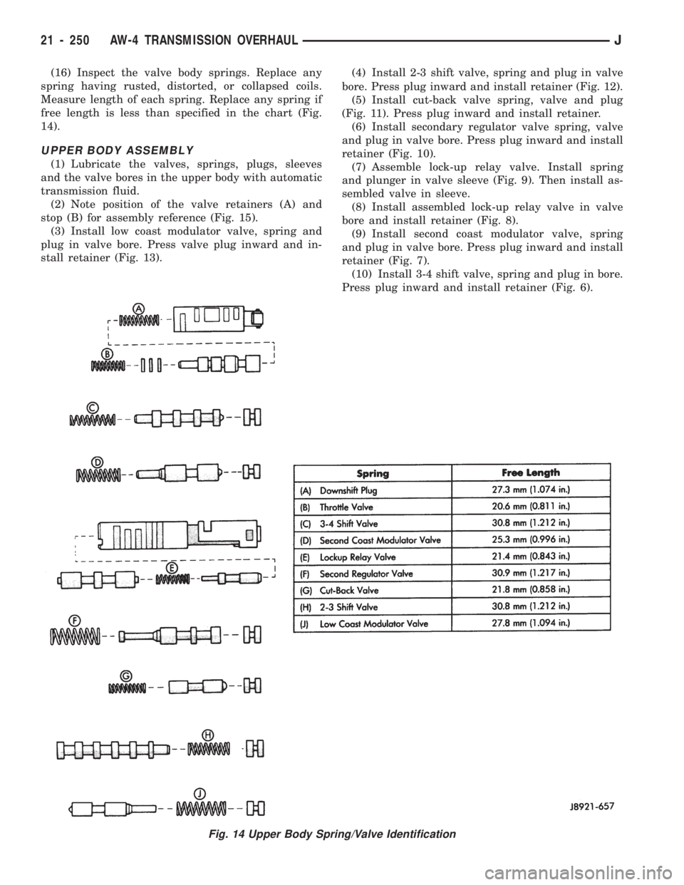
(16) Inspect the valve body springs. Replace any
spring having rusted, distorted, or collapsed coils.
Measure length of each spring. Replace any spring if
free length is less than specified in the chart (Fig.
14).
UPPER BODY ASSEMBLY
(1) Lubricate the valves, springs, plugs, sleeves
and the valve bores in the upper body with automatic
transmission fluid.
(2) Note position of the valve retainers (A) and
stop (B) for assembly reference (Fig. 15).
(3) Install low coast modulator valve, spring and
plug in valve bore. Press valve plug inward and in-
stall retainer (Fig. 13).(4) Install 2-3 shift valve, spring and plug in valve
bore. Press plug inward and install retainer (Fig. 12).
(5) Install cut-back valve spring, valve and plug
(Fig. 11). Press plug inward and install retainer.
(6) Install secondary regulator valve spring, valve
and plug in valve bore. Press plug inward and install
retainer (Fig. 10).
(7) Assemble lock-up relay valve. Install spring
and plunger in valve sleeve (Fig. 9). Then install as-
sembled valve in sleeve.
(8) Install assembled lock-up relay valve in valve
bore and install retainer (Fig. 8).
(9) Install second coast modulator valve, spring
and plug in valve bore. Press plug inward and install
retainer (Fig. 7).
(10) Install 3-4 shift valve, spring and plug in bore.
Press plug inward and install retainer (Fig. 6).
Fig. 14 Upper Body Spring/Valve Identification
21 - 250 AW-4 TRANSMISSION OVERHAULJ
Page 1362 of 1784
(11) Install throttle valve in valve bore. Push valve
into place and install valve stop (Fig. 16).
(12) On models with adjusting rings, turn upper
body over and install adjusting rings (Fig. 17). Be
sure to install same number of rings as were re-
moved.
(13) Install throttle valve adjusting spring in bore
and onto end of throttle valve (Fig. 18).
(14) Install downshift spring and plug in throttle
valve bore. Press plug inward against throttle valve
and spring and install retainer pin (Fig. 19).
(15) Install sleeve in throttle cam (Fig. 20).
Fig. 15 Valve Retainer And Stop Locations
Fig. 16 Installing Throttle Valve And Stop
Fig. 17 Install Throttle Valve Adjusting Rings (If
Equipped)
Fig. 18 Installing Throttle Valve Adjusting Spring
Fig. 19 Installing Downshift Plug
JAW-4 TRANSMISSION OVERHAUL 21 - 251
Page 1363 of 1784

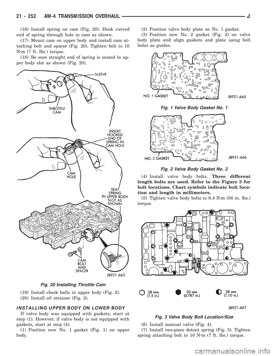
(16) Install spring on cam (Fig. 20). Hook curved
end of spring through hole in cam as shown.
(17) Mount cam on upper body and install cam at-
taching bolt and spacer (Fig. 20). Tighten bolt to 10
Nzm (7 ft. lbs.) torque.
(18) Be sure straight end of spring is seated in up-
per body slot as shown (Fig. 20).
(19) Install check balls in upper body (Fig. 2).
(20) Install oil strainer (Fig. 2).
INSTALLING UPPER BODY ON LOWER BODY
If valve body was equipped with gaskets, start at
step (1). However, if valve body is not equipped with
gaskets, start at step (4).
(1) Position new No. 1 gasket (Fig. 1) on upper
body.(2) Position valve body plate on No. 1 gasket.
(3) Position new No. 2 gasket (Fig. 2) on valve
body plate and align gaskets and plate using bolt
holes as guides.
(4) Install valve body bolts.Three different
length bolts are used. Refer to the Figure 3 for
bolt locations. Chart symbols indicate bolt loca-
tion and length in millimeters.
(5) Tighten valve body bolts to 6.4 Nzm (56 in. lbs.)
torque.
(6) Install manual valve (Fig. 4).
(7) Install two-piece detent spring (Fig. 5). Tighten
spring attaching bolt to 10 Nzm (7 ft. lbs.) torque.
Fig. 20 Installing Throttle Cam
Fig. 1 Valve Body Gasket No. 1
Fig. 2 Valve Body Gasket No. 2
Fig. 3 Valve Body Bolt Location/Size
21 - 252 AW-4 TRANSMISSION OVERHAULJ
Page 1364 of 1784
Fig. 5 Installing Detent Spring
Fig. 4 Installing Manual Valve
JAW-4 TRANSMISSION OVERHAUL 21 - 253