1994 JEEP CHEROKEE transmission
[x] Cancel search: transmissionPage 1442 of 1784
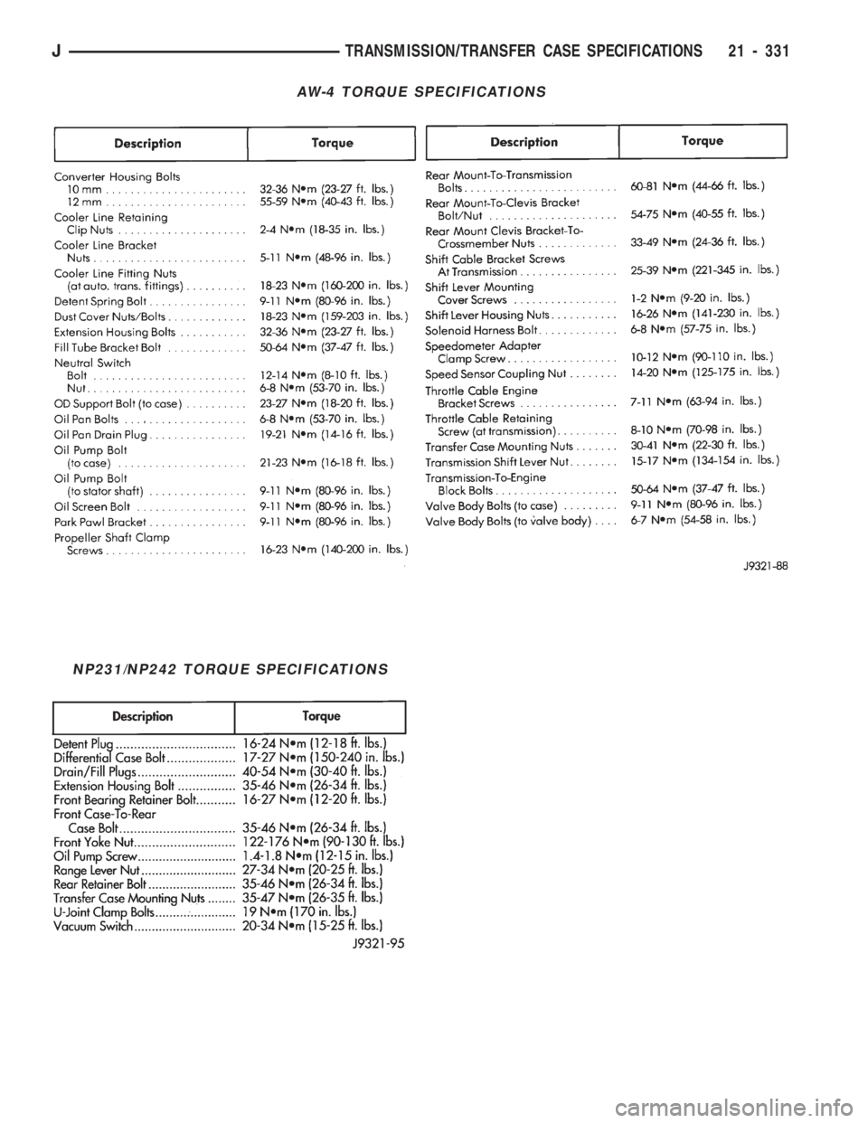
AW-4 TORQUE SPECIFICATIONS
NP231/NP242 TORQUE SPECIFICATIONS
JTRANSMISSION/TRANSFER CASE SPECIFICATIONS 21 - 331
Page 1452 of 1784
Radial runout of more than 1.5 mm (.060 inch)
measured at the center line of the tread may cause
the vehicle to shake.
Lateral runout of more than 2.0 mm (.080 inch)
measured near the shoulder of the tire may cause the
vehicle to shake.
Sometimes radial runout can be reduced. Relocate
the wheel and tire assembly on the mounting studs
(See Method 1). If this does not reduce runout to an
acceptable level, the tire can be rotated on the wheel.
(See Method 2).
METHOD 1 (RELOCATE WHEEL ON HUB)
Check accuracy of the wheel mounting surface; ad-
just wheel bearings.
Drive vehicle a short distance to eliminate tire flat
spotting from a parked position.
Make sure all wheel nuts are properly torqued.
Relocate wheel on the mounting, two studs over
from the original position.
Re-tighten wheel nuts until all are properly
torqued, to eliminate brake distortion.
Check radial runout. If still excessive, mark tire
sidewall, wheel, and stud at point of maximum
runout and proceed to Method 2.
METHOD 2 (RELOCATE TIRE ON WHEEL)
Rotating tire on wheel is particularly effective
when there is runout in both tire and wheel.Remove tire from wheel and re-mount wheel on
hub in former position.
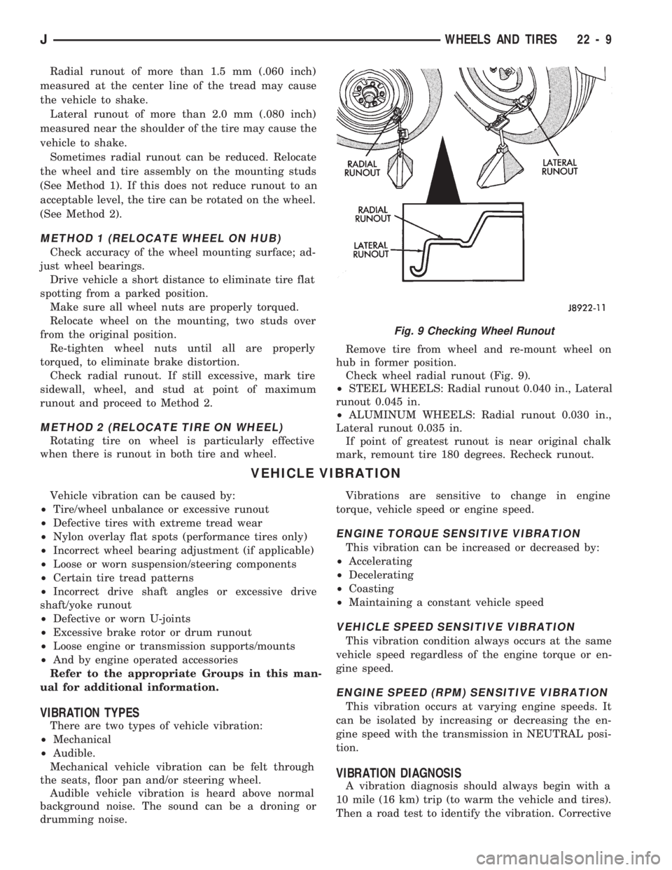
Check wheel radial runout (Fig. 9).
²STEEL WHEELS: Radial runout 0.040 in., Lateral
runout 0.045 in.
²ALUMINUM WHEELS: Radial runout 0.030 in.,
Lateral runout 0.035 in.
If point of greatest runout is near original chalk
mark, remount tire 180 degrees. Recheck runout.
VEHICLE VIBRATION
Vehicle vibration can be caused by:
²Tire/wheel unbalance or excessive runout
²Defective tires with extreme tread wear
²Nylon overlay flat spots (performance tires only)
²Incorrect wheel bearing adjustment (if applicable)
²Loose or worn suspension/steering components
²Certain tire tread patterns
²Incorrect drive shaft angles or excessive drive
shaft/yoke runout
²Defective or worn U-joints
²Excessive brake rotor or drum runout
²Loose engine or transmission supports/mounts
²And by engine operated accessories
Refer to the appropriate Groups in this man-
ual for additional information.
VIBRATION TYPES
There are two types of vehicle vibration:
²Mechanical
²Audible.
Mechanical vehicle vibration can be felt through
the seats, floor pan and/or steering wheel.
Audible vehicle vibration is heard above normal
background noise. The sound can be a droning or
drumming noise.Vibrations are sensitive to change in engine
torque, vehicle speed or engine speed.
ENGINE TORQUE SENSITIVE VIBRATION
This vibration can be increased or decreased by:
²Accelerating
²Decelerating
²Coasting
²Maintaining a constant vehicle speed
VEHICLE SPEED SENSITIVE VIBRATION
This vibration condition always occurs at the same
vehicle speed regardless of the engine torque or en-
gine speed.
ENGINE SPEED (RPM) SENSITIVE VIBRATION
This vibration occurs at varying engine speeds. It
can be isolated by increasing or decreasing the en-
gine speed with the transmission in NEUTRAL posi-
tion.
VIBRATION DIAGNOSIS
A vibration diagnosis should always begin with a
10 mile (16 km) trip (to warm the vehicle and tires).
Then a road test to identify the vibration. Corrective
Fig. 9 Checking Wheel Runout
JWHEELS AND TIRES 22 - 9
Page 1454 of 1784
mph (112 km/h) range. The incorrect angles can also
produce an audible vibration in the 20 - 50 mph (32 -
80 km/h) range. Caster adjustment could be required
to correct the angles.
UJÐUniversal Joints:Engine torque/vehicle
speed sensitive, mechanical/audible vibration. If the
U-joint is worn it will cause vibration with almost
any vehicle speed/engine torque condition.
DSYÐDrive Shaft and Yokes:Vehicle speed sen-
sitive, mechanical/audible vibration. The condition
will not cause vibration below 35 mph (56 km/h). Ex-
cessive runout, unbalance or dents and bends in the
shaft will cause the vibration. Identify the actual
cause and repair/replace as necessary.
WBÐWheel Bearings:Vehicle speed sensitive,
mechanical/audible vibration. Loose wheel bearings
cause shimmy-like vibration at 35 mph (56 km/h)
and above. Worn bearings will also produce a growl
noise at low vehicle speed and a whine noise at high
vehicle speed. The wheel bearings must be adjusted
or replaced, as applicable.
ANÐAxle Noise:Engine torque/vehicle speed sen-
sitive, mechanical/audible vibration. The axle will not
cause mechanical vibration unless the axle shaft is
bent. Worn or damaged axle pinion shaft or differen-
tial gears and bearings will cause noise. Replace the
defective component(s) as necessary.
SSCÐSuspension and Steering Components:
Vehicle speed sensitive, mechanical vibration. Wornsuspension/steering components can cause mechani-
cal vibration at speeds above 20 mph (32 km/h).
Identify and repair or replace the defective compo-
nent(s).
EAÐEngine Driven Accessories:Engine speed
sensitive, mechanical/audible vibration. Vibration can
be caused by loose or broken A/C compressor, PS
pump, water pump, generator or brackets, etc. Usu-
ally more noticeable when the transmission is shifted
into the NEUTRAL position and the engine speed
(rpm) increased. Inspect the engine driven accesso-
ries in the engine compartment. Repair/replace as
necessary.
ADBÐAccessory Drive Belts:Engine speed sen-
sitive, audible vibration. Worn drive belts can cause a
vibration that produces either a droning, fluttering or
rumbling noise. Inspect the drive belt(s) and tighten/
replace as necessary.
DEMÐDamaged Engine or Transmission Sup-
port Mounts:Engine speed sensitive, mechanical/
audible vibration. If a support mount is worn, noise
or vibration will occur. Inspect the support mounts
and repair/replace as necessary.
ESÐExhaust System:Engine speed sensitive,
mechanical/audible vibration. If loose exhaust compo-
nents contact the vehicle body they will cause noise
and vibration. Inspect the exhaust system for loose,
broken and mis-aligned components and repair/re-
place as necessary.
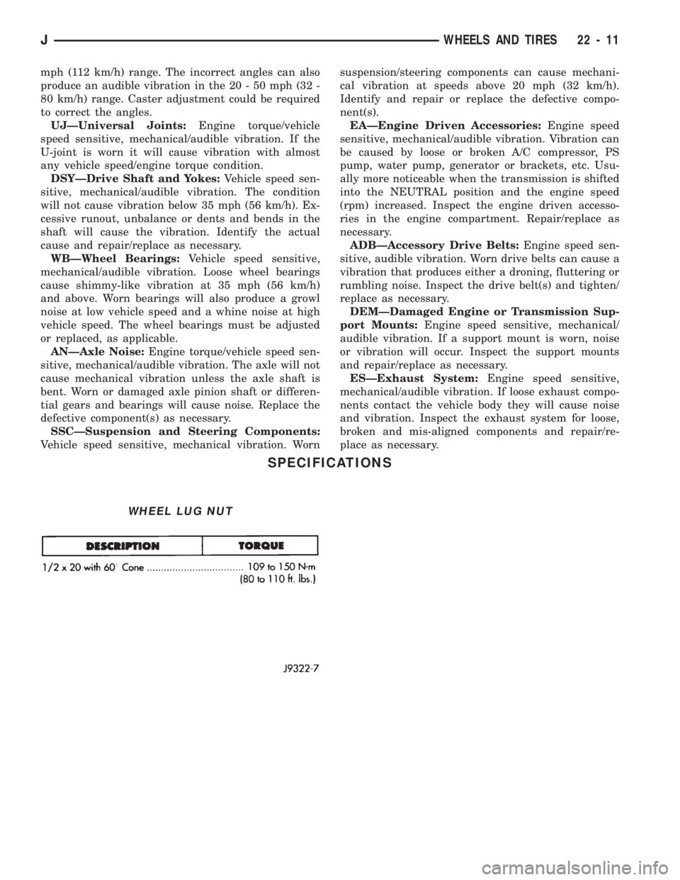
SPECIFICATIONS
WHEEL LUG NUT
JWHEELS AND TIRES 22 - 11
Page 1539 of 1784
UNDERBODY COMPONENTS
INDEX
page page
Catalytic Converter/Muffler/Tailpipe Support
Brackets............................. 85
Front Skid Plate......................... 84
Fuel and Brake Fluid Tube Retainer Clip....... 86
Fuel Filler Hose Splash ShieldÐXJ Vehicles.... 86
Fuel Filter Bracket........................ 86Fuel Tank Skid Plate...................... 84
Fuel Tank Support Strap................... 86
Rear Tow HookÐXJ Vehicles............... 87
Service Information....................... 84
Trailer Hitches........................... 88
Transfer Case Skid Plate.................. 84
SERVICE INFORMATION
In some cases, components in the following proce-
dures either support, or are concealed by other com-
ponents. When necessary, refer to component
removal procedure for service access.
FRONT SKID PLATE
REMOVAL
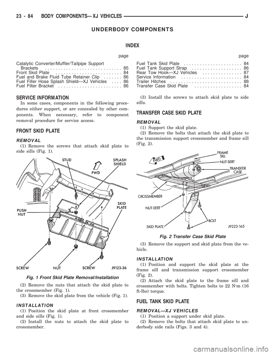
(1) Remove the screws that attach skid plate to
side sills (Fig. 1).
(2) Remove the nuts that attach the skid plate to
the crossmember (Fig. 1).
(3) Remove the skid plate from the vehicle (Fig. 1).
INSTALLATION
(1) Position the skid plate at front crossmember
and side sills (Fig. 1).
(2) Install the nuts to attach the skid plate to
crossmember.(3) Install the screws to attach skid plate to side
sills.
TRANSFER CASE SKID PLATE
REMOVAL
(1) Support the skid plate.
(2) Remove the bolts that attach the skid plate to
the transmission support crossmember and frame sill
(Fig. 2).
(3) Remove the support and skid plate from the ve-
hicle.
INSTALLATION
(1) Position and support the skid plate at the
frame sill and transmission support crossmember
(Fig. 2).
(2) Attach the skid plate to the frame sill and
crossmember with bolts. Tighten bolts to 22 Nzm (16
ft-lbs) torque.
FUEL TANK SKID PLATE
REMOVALÐXJ VEHICLES
(1) Position a support under skid plate.
(2) Remove the bolts that attach skid plate to un-
derbody side rails (Figs. 3 and 4).
Fig. 1 Front Skid Plate Removal/Installation
Fig. 2 Transfer Case Skid Plate
23 - 84 BODY COMPONENTSÐXJ VEHICLESJ
Page 1543 of 1784
The reinforcement bracket is held on the
frame rail with two blind rivets.
(2) Remove the bracket and tow hook from frame
rail.
INSTALLATION
(1) Position bracket and tow hook on the frame
rail.
(2) Install bolts that attach tow hook bracket to
frame rail and reinforcement bracket. Tighten bolts
to 75 Nzm (55 ft-lbs) torque.
TRAILER HITCHES
CLASS III HITCHÐXJ VEHICLES
A class III weight-distributing/equalizer type hitch
can be used to tow a trailer:
²having a maximum gross weight of 5,000 lbs/2250
kg, and
²having a maximum tongue weight of 750 lbs/332
kg).
The following vehicle basic equipment is required
for class III trailer towing:
²P205/75R15 or larger tires;
²full size spare tire;
²trailer sway control;
²trailer tow wire harness and connector;
²heavy duty turn signal flasher element;
²heavy duty axle (with synthetic lubricant);²heavy duty cooling system;
²heavy duty generator/battery;
²auxiliary automatic transmission fluid cooler; and
²I-6, 4.0L engine.
Wide-angle type door mirrors are recommended but
not required.
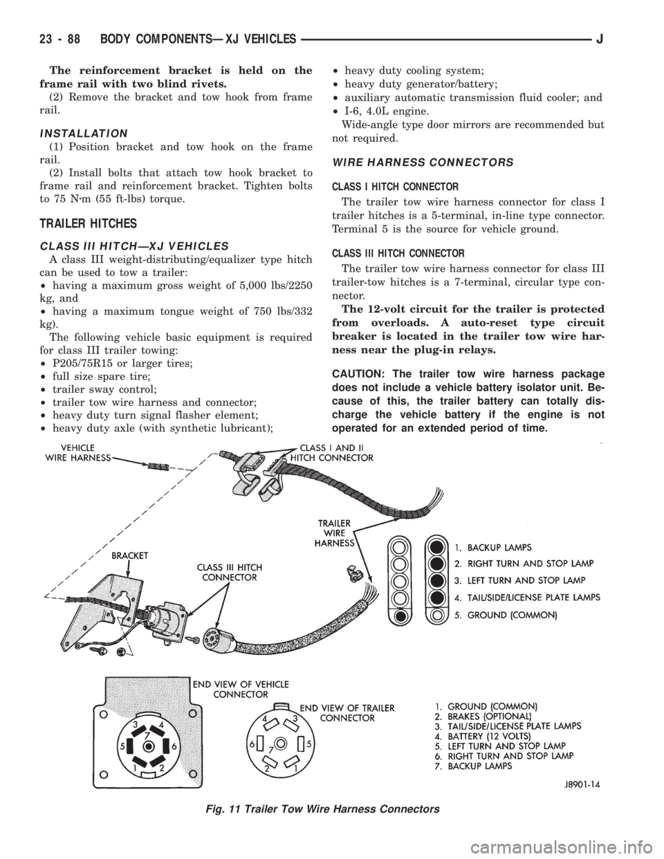
WIRE HARNESS CONNECTORS
CLASS I HITCH CONNECTOR
The trailer tow wire harness connector for class I
trailer hitches is a 5-terminal, in-line type connector.
Terminal 5 is the source for vehicle ground.
CLASS III HITCH CONNECTOR
The trailer tow wire harness connector for class III
trailer-tow hitches is a 7-terminal, circular type con-
nector.
The 12-volt circuit for the trailer is protected
from overloads. A auto-reset type circuit
breaker is located in the trailer tow wire har-
ness near the plug-in relays.
CAUTION: The trailer tow wire harness package
does not include a vehicle battery isolator unit. Be-
cause of this, the trailer battery can totally dis-
charge the vehicle battery if the engine is not
operated for an extended period of time.
Fig. 11 Trailer Tow Wire Harness Connectors
23 - 88 BODY COMPONENTSÐXJ VEHICLESJ
Page 1574 of 1784
(2) Fold the end covers over the retaining screws.
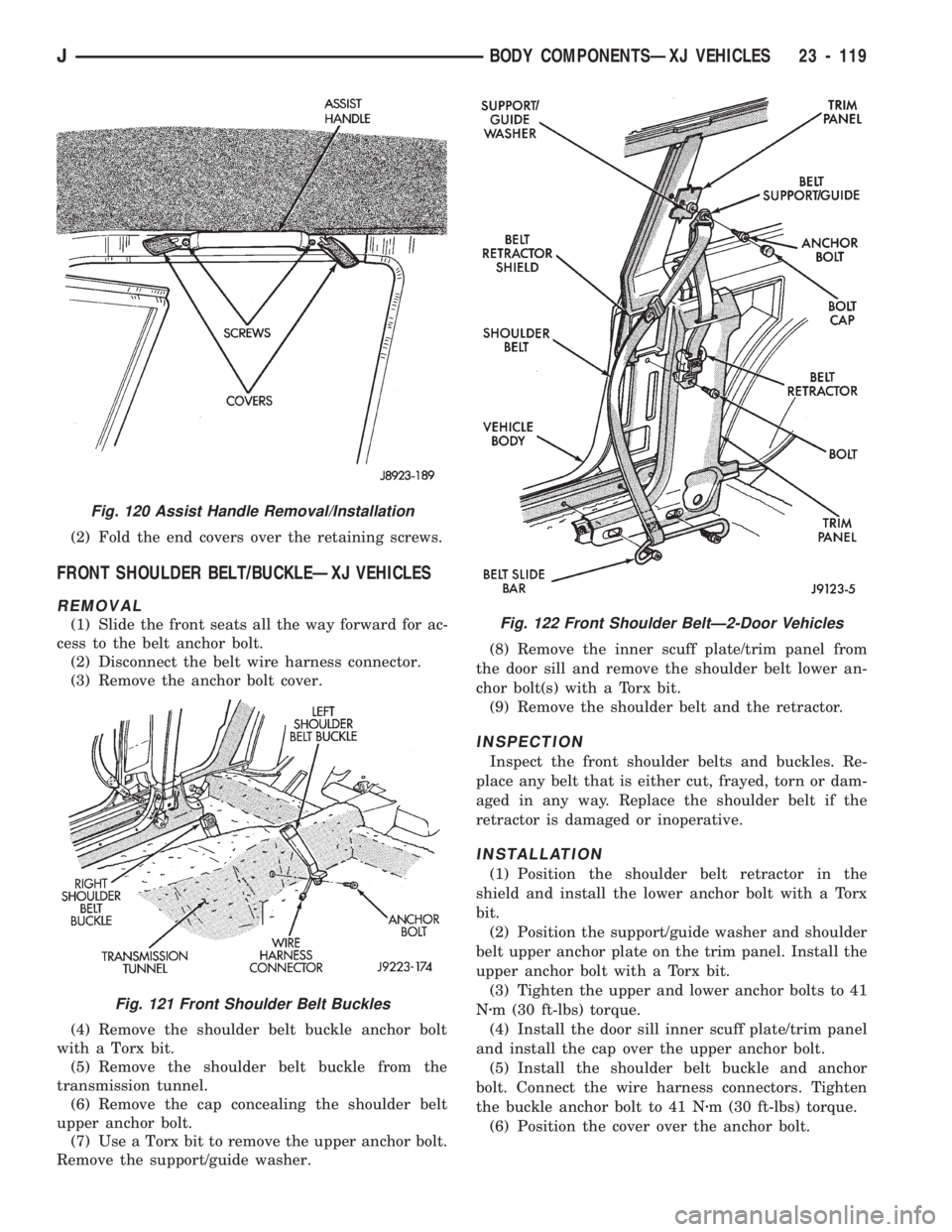
FRONT SHOULDER BELT/BUCKLEÐXJ VEHICLES
REMOVAL
(1) Slide the front seats all the way forward for ac-
cess to the belt anchor bolt.
(2) Disconnect the belt wire harness connector.
(3) Remove the anchor bolt cover.
(4) Remove the shoulder belt buckle anchor bolt
with a Torx bit.
(5) Remove the shoulder belt buckle from the
transmission tunnel.
(6) Remove the cap concealing the shoulder belt
upper anchor bolt.
(7) Use a Torx bit to remove the upper anchor bolt.
Remove the support/guide washer.(8) Remove the inner scuff plate/trim panel from
the door sill and remove the shoulder belt lower an-
chor bolt(s) with a Torx bit.
(9) Remove the shoulder belt and the retractor.
INSPECTION
Inspect the front shoulder belts and buckles. Re-
place any belt that is either cut, frayed, torn or dam-
aged in any way. Replace the shoulder belt if the
retractor is damaged or inoperative.
INSTALLATION
(1) Position the shoulder belt retractor in the
shield and install the lower anchor bolt with a Torx
bit.
(2) Position the support/guide washer and shoulder
belt upper anchor plate on the trim panel. Install the
upper anchor bolt with a Torx bit.
(3) Tighten the upper and lower anchor bolts to 41
Nzm (30 ft-lbs) torque.
(4) Install the door sill inner scuff plate/trim panel
and install the cap over the upper anchor bolt.
(5) Install the shoulder belt buckle and anchor
bolt. Connect the wire harness connectors. Tighten
the buckle anchor bolt to 41 Nzm (30 ft-lbs) torque.
(6) Position the cover over the anchor bolt.
Fig. 120 Assist Handle Removal/Installation
Fig. 121 Front Shoulder Belt Buckles
Fig. 122 Front Shoulder BeltÐ2-Door Vehicles
JBODY COMPONENTSÐXJ VEHICLES 23 - 119
Page 1579 of 1784
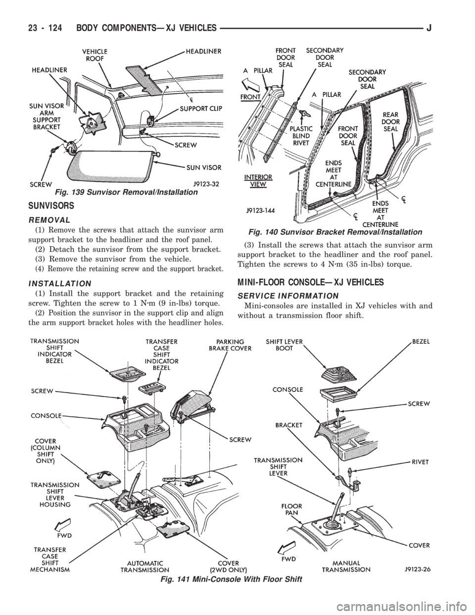
SUNVISORS
REMOVAL
(1) Remove the screws that attach the sunvisor arm
support bracket to the headliner and the roof panel.
(2) Detach the sunvisor from the support bracket.
(3) Remove the sunvisor from the vehicle.
(4) Remove the retaining screw and the support bracket.
INSTALLATION
(1) Install the support bracket and the retaining
screw. Tighten the screw to 1 Nzm (9 in-lbs) torque.
(2) Position the sunvisor in the support clip and align
the arm support bracket holes with the headliner holes.
(3) Install the screws that attach the sunvisor arm
support bracket to the headliner and the roof panel.
Tighten the screws to 4 Nzm (35 in-lbs) torque.
MINI-FLOOR CONSOLEÐXJ VEHICLES
SERVICE INFORMATION
Mini-consoles are installed in XJ vehicles with and
without a transmission floor shift.
Fig. 139 Sunvisor Removal/Installation
Fig. 140 Sunvisor Bracket Removal/Installation
Fig. 141 Mini-Console With Floor Shift
23 - 124 BODY COMPONENTSÐXJ VEHICLESJ
Page 1580 of 1784
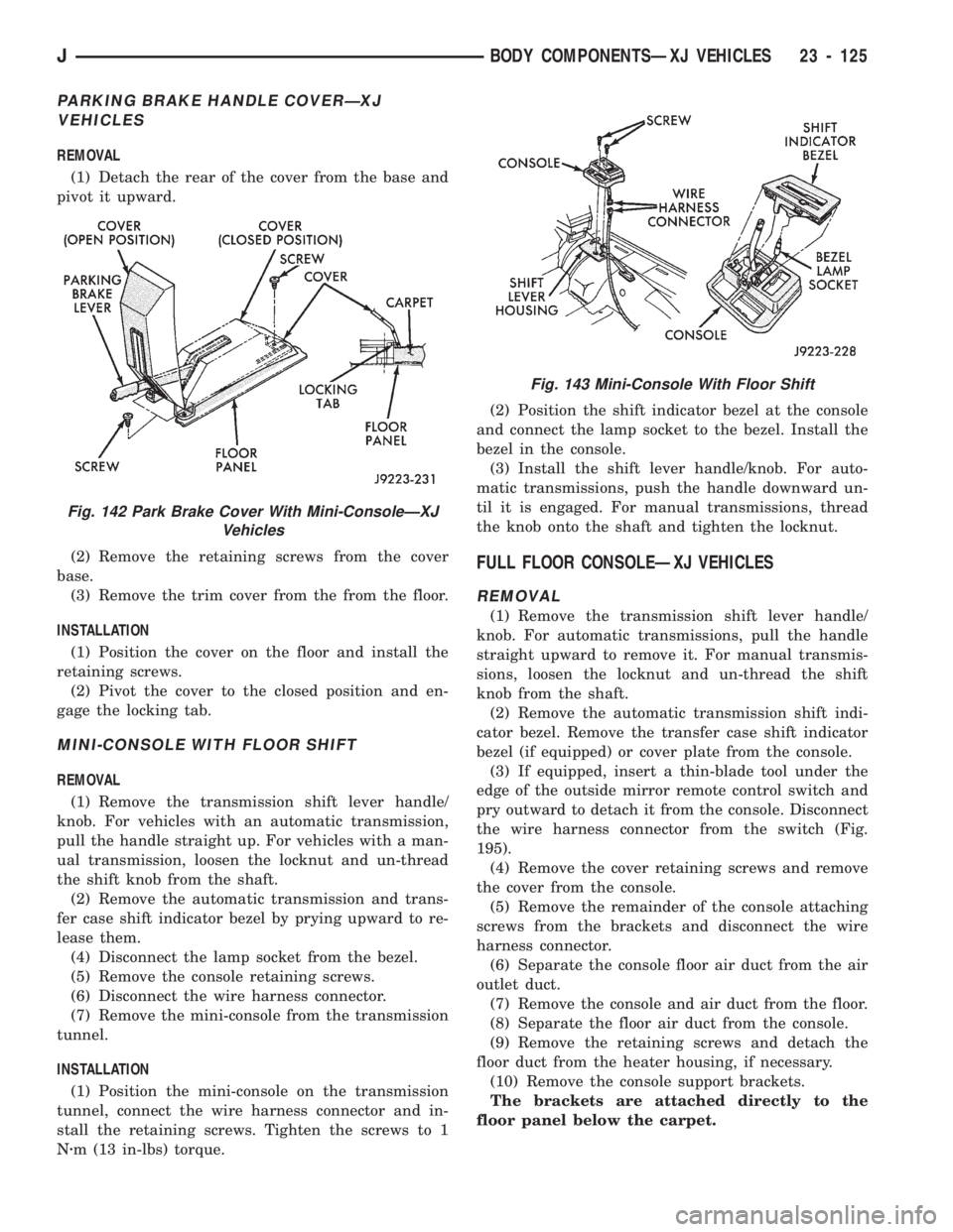
PARKING BRAKE HANDLE COVERÐXJ
VEHICLES
REMOVAL
(1) Detach the rear of the cover from the base and
pivot it upward.
(2) Remove the retaining screws from the cover
base.
(3) Remove the trim cover from the from the floor.
INSTALLATION
(1) Position the cover on the floor and install the
retaining screws.
(2) Pivot the cover to the closed position and en-
gage the locking tab.
MINI-CONSOLE WITH FLOOR SHIFT
REMOVAL
(1) Remove the transmission shift lever handle/
knob. For vehicles with an automatic transmission,
pull the handle straight up. For vehicles with a man-
ual transmission, loosen the locknut and un-thread
the shift knob from the shaft.
(2) Remove the automatic transmission and trans-
fer case shift indicator bezel by prying upward to re-
lease them.
(4) Disconnect the lamp socket from the bezel.
(5) Remove the console retaining screws.
(6) Disconnect the wire harness connector.
(7) Remove the mini-console from the transmission
tunnel.
INSTALLATION
(1) Position the mini-console on the transmission
tunnel, connect the wire harness connector and in-
stall the retaining screws. Tighten the screws to 1
Nzm (13 in-lbs) torque.(2) Position the shift indicator bezel at the console
and connect the lamp socket to the bezel. Install the
bezel in the console.
(3) Install the shift lever handle/knob. For auto-
matic transmissions, push the handle downward un-
til it is engaged. For manual transmissions, thread
the knob onto the shaft and tighten the locknut.
FULL FLOOR CONSOLEÐXJ VEHICLES
REMOVAL
(1) Remove the transmission shift lever handle/
knob. For automatic transmissions, pull the handle
straight upward to remove it. For manual transmis-
sions, loosen the locknut and un-thread the shift
knob from the shaft.
(2) Remove the automatic transmission shift indi-
cator bezel. Remove the transfer case shift indicator
bezel (if equipped) or cover plate from the console.
(3) If equipped, insert a thin-blade tool under the
edge of the outside mirror remote control switch and
pry outward to detach it from the console. Disconnect
the wire harness connector from the switch (Fig.
195).
(4) Remove the cover retaining screws and remove
the cover from the console.
(5) Remove the remainder of the console attaching
screws from the brackets and disconnect the wire
harness connector.
(6) Separate the console floor air duct from the air
outlet duct.
(7) Remove the console and air duct from the floor.
(8) Separate the floor air duct from the console.
(9) Remove the retaining screws and detach the
floor duct from the heater housing, if necessary.
(10) Remove the console support brackets.
The brackets are attached directly to the
floor panel below the carpet.
Fig. 142 Park Brake Cover With Mini-ConsoleÐXJ
Vehicles
Fig. 143 Mini-Console With Floor Shift
JBODY COMPONENTSÐXJ VEHICLES 23 - 125