1994 JEEP CHEROKEE wheel alignment
[x] Cancel search: wheel alignmentPage 1074 of 1784
(2) Wrap a single layer of plastic tape around the
pitman shaft threads and splines. This will protect
the replacement seals during installation.
(3) Install the seal with a suitable size socket.
(4) Remove the tape from the shaft.
(5) Center the steering gear.
(6) Align and install the pitman arm.
(7) Install the washer and retaining nut on the pit-
man shaft. Tighten the nut to 251 Nb1m (185 ft. lbs.)
torque.
GEAR ADJUSTMENTS IN VEHICLE
REMOVE
(1) Raise and support the vehicle.
(2) Mark the pitman shaft and pitman arm for in-
stallation reference. Remove the pitman arm from
the shaft.
(3) Loosen the adjuster lock nut then back the ad-
juster plug off 1/4 turn.
(4) Remove the steering wheel horn pad.
(5) Turn the steering wheel in one direction until
stopped by the gear. Then turn back 1/2 turn.
CAUTION: Do not turn the steering wheel hard
against the internal stops when the linkage is re-
moved. This could result in damage to the recircu-
lating ball guides.
MEASURE
Place a low calibration (50 in. lbs.) torque wrench
and socket on the steering wheel nut. Rotate the
wrench and nut through a 90 degree arc (1/4 turn).
This will measure the worm shaft bearing preload.
ADJUST WORMSHAFT BEARING PRELOAD
TORQUE
(1) Adjust the preload by tightening the adjuster
plug. The preload should be 0.6 to 1 Nzm(5to8in.
lbs.) torque.
Steering column/shaft misalignment or damage will
increase the amount of torque required to rotate the
steering wheel. If the rotating torque is exceptionally
high, inspect the steering column/shaft alignment. If
the alignment is correct, remove the steering gear,
determine the cause of the high preload torque, and
repair as necessary.
(2) Tighten the adjuster locknut to 68 Nzm (50 ft.
lbs.) torque. Measure the preload torque. If neces-
sary, adjust the preload torque again.
ADJUST OVERCENTER DRAG TORQUE
(1) Turn the steering wheel from one stop to the
other and count the total numbers of turns. Turn the
wheel back in reverse direction 1/2 the total number
of turns to center the steering gear.
(2) Turn the over center adjusting screw in to re-
move all lash between the ball nut and pitman shaftsector teeth. Hold the adjustment screw and tighten
the lock nut to 34 Nzm (25 ft. lbs.) torque.
(3) Check the torque at the steering wheel by tak-
ing the highest reading as the wheel is turned
through the center position.
(4) The overcenter drag torque should be 0.5 to 1
Nzm (4 to 10 in. lbs.).
(5) If necessary, loosen the lock nut and adjust the
over center adjuster screw to obtain the proper
torque. Re-tighten the lock nut to the lock nut.
(6) After tightening the locknut, measure the over-
center drag torque again and readjust the torque, if
necessary.
INSTALL
(1) Align the installation reference marks and in-
stall the pitman arm.
(2) Install and tighten the pitman shaft nut and
washer to 251 Nzm (185 ft. lbs.) torque.
(3) Install the horn button.
GEAR DISASSEMBLY
(1) Rotate the wormshaft from stop-to-stop and
count the number of rotations. Rotate the wormshaft
in the reverse direction 1/2 of the total number of ro-
tations to center it and the ball nut.
(2) Remove the pitman shaft adjustment screw
locknut. Remove the cover retaining bolts, cover, and
gasket (Fig. 3).
(3) Slide the adjustment screw head (Fig. 3) out of
the pitman shaft T-slot and remove it and the
shim(s).
(4) Retain the shim(s) for end-play measurement
during assembly.
(5) Remove the pitman shaft, the wormshaft bear-
ing preload torque adjustment cap locknut, and the
adjustment cap (Fig. 2).
(6) Remove the wormshaft and the ball nut (Fig.
2).
(7) Remove (pry) the pitman shaft and the worm-
shaft seals from the steering gear housing (Fig. 3).
WORMSHAFT AND BALL NUT DISASSEMBLY
(1) Remove the upper bearing from the wormshaft
(Fig. 2).
CAUTION: Do not allow the ball nut to rotate freely
and travel to either extreme end of the wormshaft.
This could damage the tangs at the ends of the re-
circulating ball guides (Fig. 3).
(2) Remove the recirculating ball guide clamp re-
taining screws, the clamp and the guides (Fig. 2).
Separate the half-guides and place the recirculating
balls aside in a container.
(3) Hold the ball nut over a cloth. Remove the re-
maining recirculating balls by rotating the worm-
shaft back and forth.
JSTEERING 19 - 37
Page 1082 of 1784
STEERING COLUMN GENERAL SERVICE
INDEX
page page
Column ReplacementÐXJ.................. 46
Column ReplacementÐYJ.................. 48
Park-Lock CableÐConsole Shift Automatic..... 45Service Information....................... 45
Steering Wheel.......................... 45
SERVICE INFORMATION
The column may be disassembled and reassembled.
Also most steering column components can be ser-
viced without removing the column from the vehicle.
For additional information, refer to Group 8H, Elec-
trical.
CAUTION: Bumping, jolting and hammering on the
steering column shaft and gear shift tube must be
avoided during all service procedures.
CAUTION: Disconnect negative (ground) cable from
the battery before servicing any component on the
column.
Safety goggles should be worn at all times
when involved with steering column service.
STEERING WHEEL
REMOVAL
(1) Make sure the front wheels are in thestraight
aheadposition.
(2) Disconnect the negative (ground) cable from the
battery.
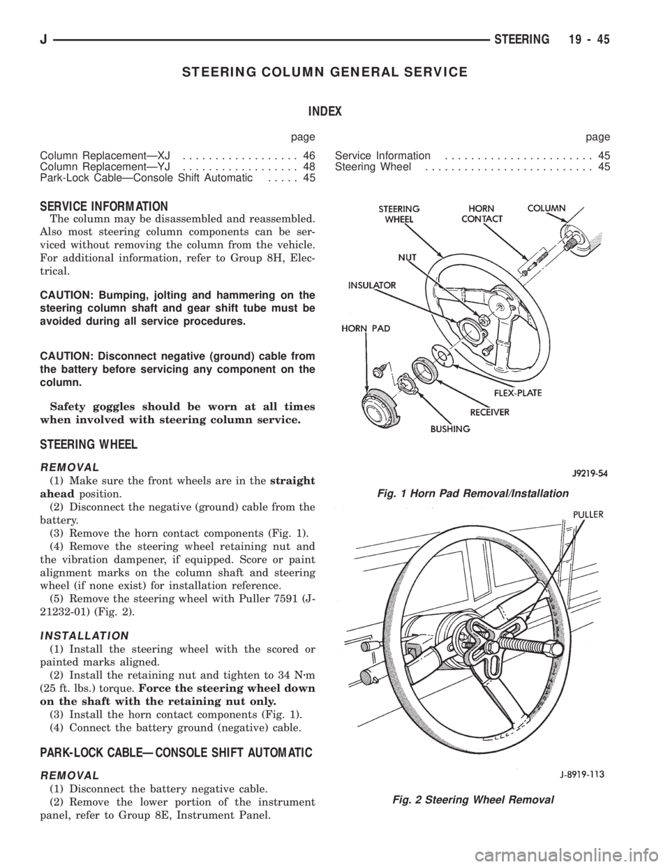
(3) Remove the horn contact components (Fig. 1).
(4) Remove the steering wheel retaining nut and
the vibration dampener, if equipped. Score or paint
alignment marks on the column shaft and steering
wheel (if none exist) for installation reference.
(5) Remove the steering wheel with Puller 7591 (J-
21232-01) (Fig. 2).
INSTALLATION
(1) Install the steering wheel with the scored or
painted marks aligned.
(2) Install the retaining nut and tighten to 34 Nzm
(25 ft. lbs.) torque.Force the steering wheel down
on the shaft with the retaining nut only.
(3) Install the horn contact components (Fig. 1).
(4) Connect the battery ground (negative) cable.
PARK-LOCK CABLEÐCONSOLE SHIFT AUTOMATIC
REMOVAL
(1) Disconnect the battery negative cable.
(2) Remove the lower portion of the instrument
panel, refer to Group 8E, Instrument Panel.
Fig. 1 Horn Pad Removal/Installation
Fig. 2 Steering Wheel Removal
JSTEERING 19 - 45
Page 1106 of 1784
STEERING RHD
GENERAL SERVICE PROCEDURE INFORMATION
Right hand drive service procedures and torque
specifications involving steering; linkage, gear and
column are the same as left hand drive vehicles ex-
cept where shown. Refer to appropriate service proce-
dures regarding each component in the system.
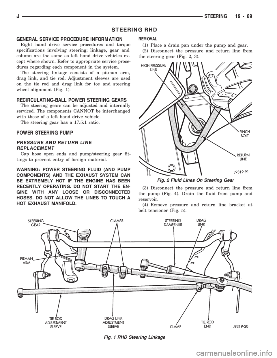
The steering linkage consists of a pitman arm,
drag link, and tie rod. Adjustment sleeves are used
on the tie rod and drag link for toe and steering
wheel alignment (Fig. 1).
RECIRCULATING-BALL POWER STEERING GEARS
The steering gears can be adjusted and internally
serviced. The components CANNOT be interchanged
with those of a left hand drive vehicle.
The steering gear has a 17.5:1 ratio.
POWER STEERING PUMP
PRESSURE AND RETURN LINE
REPLACEMENT
Cap hose open ends and pump/steering gear fit-
tings to prevent entry of foreign material.
WARNING: POWER STEERING FLUID (AND PUMP
COMPONENTS) AND THE EXHAUST SYSTEM CAN
BE EXTREMELY HOT IF THE ENGINE HAS BEEN
RECENTLY OPERATING. DO NOT START THE EN-
GINE WITH ANY LOOSE OR DISCONNECTED
HOSES. DO NOT ALLOW THE LINES TO TOUCH A
HOT EXHAUST MANIFOLD.REMOVAL
(1) Place a drain pan under the pump and gear.
(2) Disconnect the pressure and return line from
the steering gear (Fig. 2, 3).
(3) Disconnect the pressure and return line from
the pump (Fig. 4). Drain the fluid from pump and
reservoir.
(4) Remove pressure and return line bracket at
belt tensioner (Fig. 5).
Fig. 1 RHD Steering Linkage
Fig. 2 Fluid Lines On Steering Gear
JSTEERING 19 - 69
Page 1449 of 1784
WHEELS
GENERAL INFORMATION
Original equipment wheels are designed for the
specified Maximum Vehicle Capacity.
All models use steel or cast aluminum drop center
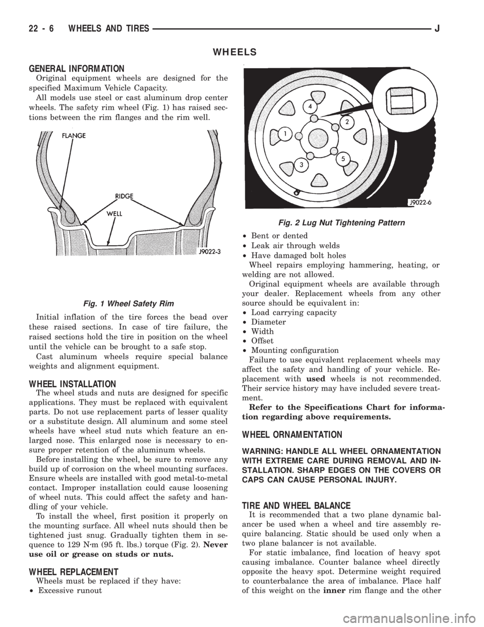
wheels. The safety rim wheel (Fig. 1) has raised sec-
tions between the rim flanges and the rim well.
Initial inflation of the tire forces the bead over
these raised sections. In case of tire failure, the
raised sections hold the tire in position on the wheel
until the vehicle can be brought to a safe stop.
Cast aluminum wheels require special balance
weights and alignment equipment.
WHEEL INSTALLATION
The wheel studs and nuts are designed for specific
applications. They must be replaced with equivalent
parts. Do not use replacement parts of lesser quality
or a substitute design. All aluminum and some steel
wheels have wheel stud nuts which feature an en-
larged nose. This enlarged nose is necessary to en-
sure proper retention of the aluminum wheels.
Before installing the wheel, be sure to remove any
build up of corrosion on the wheel mounting surfaces.
Ensure wheels are installed with good metal-to-metal
contact. Improper installation could cause loosening
of wheel nuts. This could affect the safety and han-
dling of your vehicle.
To install the wheel, first position it properly on
the mounting surface. All wheel nuts should then be
tightened just snug. Gradually tighten them in se-
quence to 129 Nzm (95 ft. lbs.) torque (Fig. 2).Never
use oil or grease on studs or nuts.
WHEEL REPLACEMENT
Wheels must be replaced if they have:
²Excessive runout²Bent or dented
²Leak air through welds
²Have damaged bolt holes
Wheel repairs employing hammering, heating, or
welding are not allowed.
Original equipment wheels are available through
your dealer. Replacement wheels from any other
source should be equivalent in:
²Load carrying capacity
²Diameter
²Width
²Offset
²Mounting configuration
Failure to use equivalent replacement wheels may
affect the safety and handling of your vehicle. Re-
placement withusedwheels is not recommended.
Their service history may have included severe treat-
ment.
Refer to the Specifications Chart for informa-
tion regarding above requirements.
WHEEL ORNAMENTATION
WARNING: HANDLE ALL WHEEL ORNAMENTATION
WITH EXTREME CARE DURING REMOVAL AND IN-
STALLATION. SHARP EDGES ON THE COVERS OR
CAPS CAN CAUSE PERSONAL INJURY.
TIRE AND WHEEL BALANCE
It is recommended that a two plane dynamic bal-
ancer be used when a wheel and tire assembly re-
quire balancing. Static should be used only when a
two plane balancer is not available.
For static imbalance, find location of heavy spot
causing imbalance. Counter balance wheel directly
opposite the heavy spot. Determine weight required
to counterbalance the area of imbalance. Place half
of this weight on theinnerrim flange and the other
Fig. 2 Lug Nut Tightening Pattern
Fig. 1 Wheel Safety Rim
22 - 6 WHEELS AND TIRESJ
Page 1474 of 1784
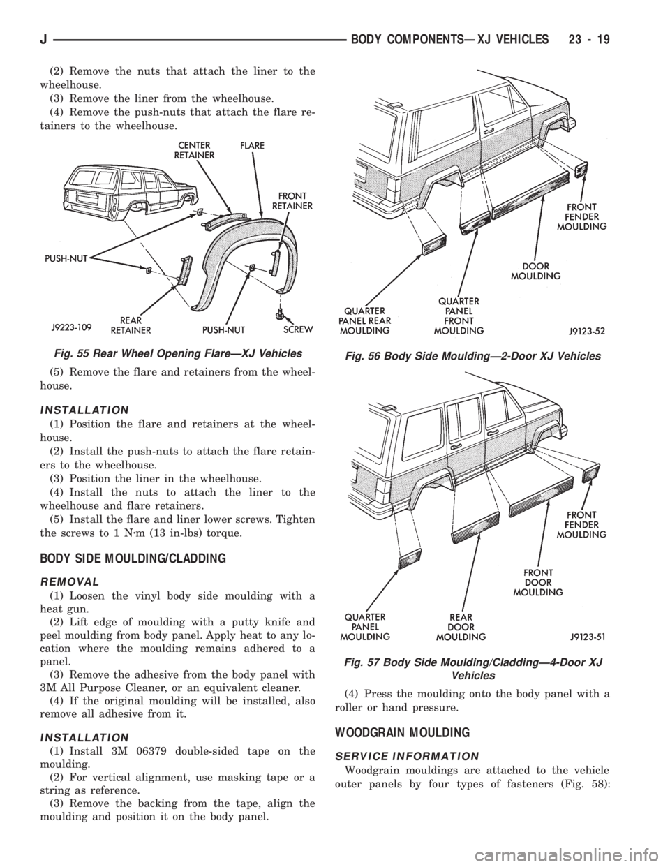
(2) Remove the nuts that attach the liner to the
wheelhouse.
(3) Remove the liner from the wheelhouse.
(4) Remove the push-nuts that attach the flare re-
tainers to the wheelhouse.
(5) Remove the flare and retainers from the wheel-
house.
INSTALLATION
(1) Position the flare and retainers at the wheel-
house.
(2) Install the push-nuts to attach the flare retain-
ers to the wheelhouse.
(3) Position the liner in the wheelhouse.
(4) Install the nuts to attach the liner to the
wheelhouse and flare retainers.
(5) Install the flare and liner lower screws. Tighten
the screws to 1 Nzm (13 in-lbs) torque.
BODY SIDE MOULDING/CLADDING
REMOVAL
(1) Loosen the vinyl body side moulding with a
heat gun.
(2) Lift edge of moulding with a putty knife and
peel moulding from body panel. Apply heat to any lo-
cation where the moulding remains adhered to a
panel.
(3) Remove the adhesive from the body panel with
3M All Purpose Cleaner, or an equivalent cleaner.
(4) If the original moulding will be installed, also
remove all adhesive from it.
INSTALLATION
(1) Install 3M 06379 double-sided tape on the
moulding.
(2) For vertical alignment, use masking tape or a
string as reference.
(3) Remove the backing from the tape, align the
moulding and position it on the body panel.(4) Press the moulding onto the body panel with a
roller or hand pressure.
WOODGRAIN MOULDING
SERVICE INFORMATION
Woodgrain mouldings are attached to the vehicle
outer panels by four types of fasteners (Fig. 58):
Fig. 56 Body Side MouldingÐ2-Door XJ Vehicles
Fig. 57 Body Side Moulding/CladdingÐ4-Door XJ
Vehicles
Fig. 55 Rear Wheel Opening FlareÐXJ Vehicles
JBODY COMPONENTSÐXJ VEHICLES 23 - 19
Page 1589 of 1784
EXTERIOR COMPONENTS
INDEX
page page
Battery Tray........................... 140
Body Extension Panels and FasciasÐYJ
Renegade Vehicles..................... 147
Body Side Step Moulding................. 145
Body Stripes/Decals..................... 153
Cowl Grille and Screen................... 139
Cowl Weatherstrip Seal................... 139
Exterior Nameplates (Adhesive-Backed)....... 158
External Spare/Wheel Tire Carrier........... 172
Fender Flare........................... 144
Fender Inner Splash Shields............... 147
Fender Splash Aprons.................... 147
Fenders............................... 141
Fog LampÐYJ Renegade Vehicles.......... 150
Front Fascia and Skid PlateÐYJ Renegade
Vehicles............................. 148
Front Fender Extension PanelÐYJ Renegade
Vehicles............................. 149
Fuel Filler Protector/Nozzle................ 158
Half Metal Door Mirror (External)............ 158
Hard Top Liftgate Glass.................. 162
Hard Top Repair........................ 165
Hard Top Roof Vent..................... 165
Hard Top Service....................... 164
Hard Top Service Information.............. 164Hood................................. 137
Hood Alignment......................... 138
Hood Insulator Panel..................... 138
Hood Safety Latch....................... 139
Liftgate Glass Weatherstrip Seal Replacement . . 163
Radiator Grille Applique................... 134
Rear Fascia and Skid PlateÐYJ Renegade
Vehicles............................. 152
Rear Quarter Extension PanelÐYJ Renegade
Vehicles............................. 151
Rocker Extension PanelÐYJ Renegade
Vehicles............................. 150
Soft Top Service........................ 167
Soft Top Service Information............... 166
Sport Bar............................. 171
Tailgate Adjustment...................... 160
Tailgate Hinge.......................... 159
Tailgate Latch and Release Handle.......... 160
Tailgate Latch Striker..................... 161
Tailgate Lock Cylinder.................... 160
Tailgate Service......................... 159
Tailgate Service Information................ 159
Tailgate Weatherstrip Seal................. 161
Wheelhouse Splash Liners................ 146
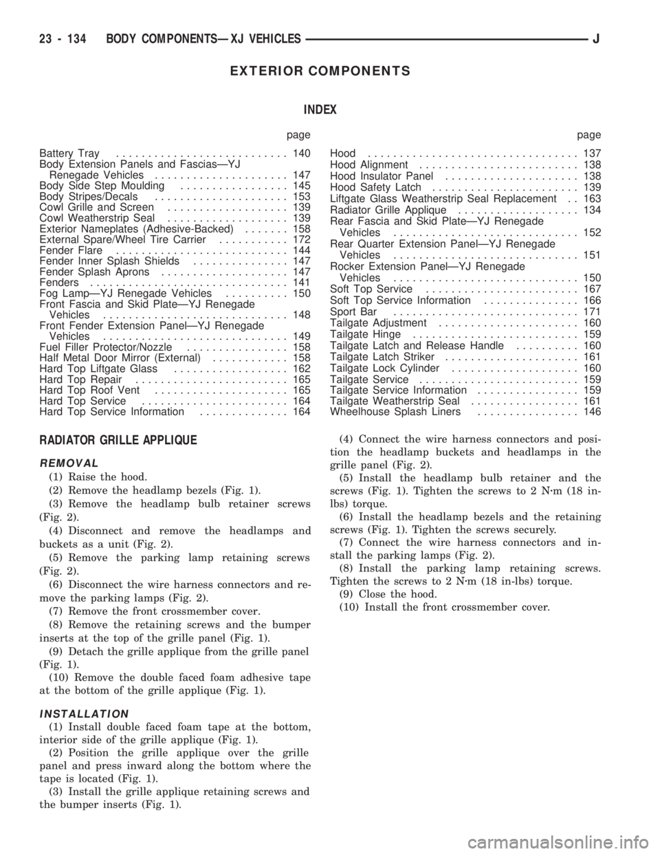
RADIATOR GRILLE APPLIQUE
REMOVAL
(1) Raise the hood.
(2) Remove the headlamp bezels (Fig. 1).
(3) Remove the headlamp bulb retainer screws
(Fig. 2).
(4) Disconnect and remove the headlamps and
buckets as a unit (Fig. 2).
(5) Remove the parking lamp retaining screws
(Fig. 2).
(6) Disconnect the wire harness connectors and re-
move the parking lamps (Fig. 2).
(7) Remove the front crossmember cover.
(8) Remove the retaining screws and the bumper
inserts at the top of the grille panel (Fig. 1).
(9) Detach the grille applique from the grille panel
(Fig. 1).
(10) Remove the double faced foam adhesive tape
at the bottom of the grille applique (Fig. 1).
INSTALLATION
(1) Install double faced foam tape at the bottom,
interior side of the grille applique (Fig. 1).
(2) Position the grille applique over the grille
panel and press inward along the bottom where the
tape is located (Fig. 1).
(3) Install the grille applique retaining screws and
the bumper inserts (Fig. 1).(4) Connect the wire harness connectors and posi-
tion the headlamp buckets and headlamps in the
grille panel (Fig. 2).
(5) Install the headlamp bulb retainer and the
screws (Fig. 1). Tighten the screws to 2 Nzm (18 in-
lbs) torque.
(6) Install the headlamp bezels and the retaining
screws (Fig. 1). Tighten the screws securely.
(7) Connect the wire harness connectors and in-
stall the parking lamps (Fig. 2).
(8) Install the parking lamp retaining screws.
Tighten the screws to 2 Nzm (18 in-lbs) torque.
(9) Close the hood.
(10) Install the front crossmember cover.
23 - 134 BODY COMPONENTSÐXJ VEHICLESJ
Page 1745 of 1784
30RH/32RH AUTOMATIC TRANSMISSION . . . 21-66
30RH/32RH GENERAL SPECIFICATIONS . . . 21-322
30RH/32RH IN-VEHICLE SERVICE.........21-96
30RH/32RH PRESSURE TEST
SPECIFICATIONS....................21-323
30RH/32RH SNAP RING/THRUST
WASHER/THRUST PLATE
SPECIFICATIONS....................21-322
30RH/32RH TORQUE SPECIFICATIONS....21-323
30RH/32RH TRANSMISSION DIAGNOSIS . . . 21-69,
21-77,21-78,21-79,21-80,21-81,21-82,21-83,21-84,
21-85
30RH/32RH TRANSMISSION OVERHAUL . . . 21-112
30RH/32RH TRANSMISSION REMOVAL
AND INSTALLATION..................21-108
3-2 DOWNSHIFT, HYDRAULIC FLOW
DURING FULL THROTTLE..............21-92
3-2 DOWNSHIFT, HYDRAULIC FLOW
DURING PART THROTTLE..............21-91
4WD INDICATOR......................8E-22
4WD INDICATOR INOPERATIVE............8E-4
4WD INDICATOR LAMP..................8E-2
60-WAY CONNECTOR, POWERTRAIN
CONTROL MODULE (PCM).............14-38
ABBREVIATIONS, SYMBOLS, FUSES........8W-6
ABS BRAKE DIAGNOSIS...................5-3
ABS BRAKES, BRAKE BLEEDINGÐWITH.....5-14
ABS COMPONENT SERVICE...............5-47
ABS FAULT DIAGNOSIS................5-4,5-6
ABS OPERATION IN ANTILOCK BRAKING
MODE..............................5-43
ABS OPERATION IN NORMAL BRAKING
MODE..............................5-43
ABS SYSTEM OPERATION................5-39
ABS SYSTEM WIRING AND ELECTRICAL
CIRCUITS............................5-4
ABS WARNING LIGHT DISPLAY.............5-3
ABSOLUTE PRESSURE (MAP) SENSOR,
MANIFOLD; FUEL SYSTEM.............14-57
ABSOLUTE PRESSURE (MAP) SENSOR,
MANIFOLD; IGNITION SYSTEMS....8D-5,8D-27
ABSOLUTE PRESSURE (MAP) SENSORÐ
PCM INPUT, MANIFOLD...............14-21
ABSOLUTE PRESSURE (MAP) SENSOR
TEST, MANIFOLD; FUEL SYSTEM........14-44
ABSOLUTE PRESSURE (MAP) SENSOR
TEST, MANIFOLD; IGNITION
SYSTEMS..........................8D-14
ABSORBER, SHOCK; FRONT
SUSPENSION AND AXLE............2-12,2-14
ABSORBER, SHOCK; REAR SUSPENSION
AND AXLES........................3-3,3-5
A/C BLOWER MOTOR...................24-43
A/C CONDENSER......................24-42
A/C CONTROL PANEL...................24-41
A/C CONTROL PANEL REPLACEMENT,
HEATER ............................24-26
A/C OPERATION........................24-1
A/C PERFORMANCE TEST................24-8
A/C RECIRCULATING AIR DOOR
VACUUM MOTOR REPLACEMENT........24-31
ACCELERATION SENSOR INSTALLATION.....5-52
ACCELERATION SENSOR REMOVAL........5-52
ACCELERATION SWITCH.................5-41
ACCELERATION SWITCH OPERATION.......5-45
ACCELERATOR PEDAL..................14-16
ACCELERATOR PEDAL AND THROTTLE
CABLE........................14-16,14-54
ACCENT PAINT.......................23-202
ACCESSORY DRIVE BELT.................0-20
ACCESSORY DRIVE BELTS, ENGINE........7-31
ACCUMULATOR PISTONS AND SPRINGS . . 21-179
ACTUATOR MOTOR STALL TEST...........8P-6
ADAPTER HOUSING AND PARK LOCK
COMPONENT OVERHAUL.............21-120
ADAPTER HOUSING SEAL REPLACEMENT . . 21-182
ADD-A-TRUNK.......................23-199
ADJUSTER PLUG ASSEMBLY
REPLACEMENT......................19-27
ADJUSTMENT, BRAKELIGHT SWITCH.......5-66
ADJUSTMENT, DIFFERENTIAL SHIM
PACK MEASUREMENT..................2-42
ADJUSTMENT, DOOR LATCH
.............23-55
ADJUSTMENT, DRUM BRAKE
..............5-35
ADJUSTMENT, FOG LAMP BEAM
..........8L-12
ADJUSTMENT, FRONT BAND
.............21-99ADJUSTMENT, HEADLAMP BEAM..........8L-3
ADJUSTMENT, HOOD....................23-9
ADJUSTMENT, LIFTGATE................23-70
ADJUSTMENTÐMAJOR, DOOR
ALIGNMENT.........................23-47
ADJUSTMENTÐMINOR, DOOR
ALIGNMENT.........................23-46
ADJUSTMENT, PARK INTERLOCK CABLE . . . 21-186
ADJUSTMENT, PARKING BRAKE...........5-63
ADJUSTMENT, PRELIMINARY
INSPECTION.......................21-167
ADJUSTMENT PROCEDURES,
TRANSMISSION ASSEMBLY...........21-146
ADJUSTMENT, REAR BAND..............21-99
ADJUSTMENT, SHIFT CABLE............21-186
ADJUSTMENT, SHIFT LINKAGE....21-275,21-296
ADJUSTMENT, TAILGATE...............23-160
ADJUSTMENT, TRANSMISSION
ASSEMBLY..............21-15,21-51,21-255
ADJUSTMENT, TRANSMISSION
THROTTLE CABLE..............21-98,21-185
ADJUSTMENT, TRANSMISSION
THROTTLE VALVE CABLE..............21-70
ADJUSTMENT, VALVE BODY ASSEMBLY . . . 21-144
ADJUSTMENT, WHEEL SENSOR AIR GAP....5-49
ADJUSTMENT (XJ), PARK INTERLOCK
CABLE.............................21-97
ADJUSTMENT (XJ), SHIFT CABLE.........21-97
ADJUSTMENT (YJ), GEARSHIFT LINKAGE . . . 21-96
ADJUSTMENTS, ALIGNMENT
MEASUREMENTS......................2-6
ADJUSTMENTS IN VEHICLE, GEAR........19-37
ADJUSTMENTS ON BENCH, GEAR.........19-42
ADJUSTMENTS, SPECIFICATIONS AND
BAND..............................21-66
ADJUSTMENTS, STEERING GEAR.........19-22
AIR CLEANER..........................25-7
AIR CLEANER FILTER ELEMENT, ENGINE....0-16
AIR CLEANER HOUSING; EMISSION
CONTROL SYSTEMS...................25-8
AIR CLEANER HOUSING; FUEL SYSTEM....14-54
AIR CONDITIONER COMPRESSOR/HOSES/
FITTINGS............................0-21
AIR CONDITIONING CLUTCH RELAY.......14-54
AIR CONDITIONING CLUTCH RELAYÐ
PCM OUTPUT.......................14-24
AIR CONDITIONING CONTROLSÐPCM
INPUT.............................14-19
AIR CONDITIONING, DESCRIPTION........24-41
AIR CONDITIONING SCHEMATIC..........24-25
AIR CONDITIONING SYSTEM DIAGNOSIS . . . 24-12
AIR CONDITIONING SYSTEMÐXJ
VEHICLES..........................24-14
AIR CONDITIONING SYSTEMÐYJ
VEHICLES..........................24-15
AIR CONTROL (IAC) MOTOR, IDLE........14-56
AIR CONTROL (IAC) MOTORÐPCM
OUTPUT, IDLE.......................14-25
AIR CONTROL MOTOR TEST, IDLE........14-46
AIR DEFLECTOR, COWL WEATHERSTRIP
SEAL/CROSSMEMBER.................23-10
AIR DOOR VACUUM MOTOR, FRESH.......24-41
AIR DOOR VACUUM MOTOR
REPLACEMENT, A/C RECIRCULATING.....24-31
AIR EXHAUST GRILLEÐXJ VEHICLES......23-30
AIR FILTER; EMISSION CONTROL
SYSTEMS...........................25-9
AIR FILTER; FUEL SYSTEM..............14-54
AIR GAP ADJUSTMENT, WHEEL SENSOR....5-49
AIR GAP, REAR SPEED SENSOR............5-3
AIR INTAKE DUCT, FRESH...............24-41
AIR PRESSURE TEST...................21-73
AIR, PURGING COMPRESSOR OF.........24-17
AIR TEMPERATURE SENSOR, INTAKE......14-54
AIR TEMPERATURE SENSOR, INTAKE
MANIFOLD.....................8D-5,8D-27
AIR TEMPERATURE SENSORÐPCM
INPUT, INTAKE.......................14-20
AIR TEMPERATURE, SENSOR RESISTANCE
(OHMS)ÐCOOLANT TEMPERATURE
SENSOR/MANIF; FUEL SYSTEM
.........14-43
AIR TEMPERATURE SENSOR TEST,
INTAKE
............................14-43
AIR TEMPERATURE SENSOR TEST,
INTAKE MANIFOLD
...................8D-14
AIR VENTILATION, FRESH
...............24-39AIRFLOW DIAGRAM....................24-23
ALIGNMENT ADJUSTMENTÐMAJOR,
DOOR.............................23-47
ALIGNMENT ADJUSTMENTÐMINOR,
DOOR.............................23-46
ALIGNMENT, FRAME...................13-10
ALIGNMENT, FRONT WHEEL...............2-5
ALIGNMENT, HOOD...................23-138
ALIGNMENT MEASUREMENTS AND
ADJUSTMENTS........................2-6
ALIGNMENTÐMINOR, XJ DOOR..........23-46
ALIGNMENT, REAR AXLE..................3-8
ALIGNMENT SPECIFICATIONSÐXJ
VEHICLES............................2-9
ALIGNMENT SPECIFICATIONSÐYJ VEHICLES . . 2-9
ANALYSIS, BACKLASH AND CONTACT
PATTERN; FRONT SUSPENSION AND AXLE . 2-44
ANALYSIS, BACKLASH AND CONTACT
PATTERN; REAR SUSPENSION AND AXLES . 3-25
ANCHOR AND BUMPER, LIFTGATE
LICENSE PLATE SCREW...............23-72
ANGLE MEASUREMENT, UNIVERSAL
JOINT..............................16-4
ANTENNA, RADIO.......................8F-8
ANTENNA TESTS.......................8F-9
ANTILOCK BRAKE SYSTEM (ABS)...........5-1
ANTI-LOCK BRAKE SYSTEM (ABS)
INDICATOR LAMP.....................8E-2
ANTILOCK BRAKE SYSTEM OPERATION.....5-43
ANTILOCK BRAKING MODE, ABS
OPERATION..........................5-43
ANTI-LOCK INDICATOR..................8E-4
ANTILOCK MODE, VEHICLE RESPONSE.......5-3
APPLICATION CHARTS, GEARTRAIN
OPERATION........................21-159
APPLICATION, PAINT..................23-201
APPLICATION, TRANSMISSION...........21-66
APPLIQUE, RADIATOR GRILLE
...........23-134
APPLIQUEÐXJ VEHICLES, QUARTER
WINDOW
...........................23-29
APRONS, FENDER SPLASH
.............23-147
ARM AND PIVOT ASSEMBLY
REPLACEMENT, FRONT WIPER
...........8K-9
ARM, LOWER SUSPENSION
...............2-11
ARM, PITMAN
...................19-15,19-18
ARM REPLACEMENT, FRONT WIPER
........8K-8
ARM REPLACEMENT, REAR WIPER
........8K-12
ARM, UPPER SUSPENSION
...............2-11
ARMS, ROCKER
....................9-19,9-59
ASH RECEIVER TRAY LAMP, I/P
..........23-92
ASSEMBLY AND ADJUSTMENT
PROCEDURES, TRANSMISSION
........21-146
ASSEMBLY AND ADJUSTMENT,
TRANSMISSION
..........21-15,21-51,21-255
ASSEMBLY AND ADJUSTMENT, VALVE
BODY
.............................21-144
ASSEMBLY, CALIPER
....................5-29
ASSEMBLY, DIFFERENTIAL; FRONT
SUSPENSION AND AXLE
................2-36
ASSEMBLY, DIFFERENTIAL; REAR
SUSPENSION AND AXLES
...............3-19
ASSEMBLY, FINAL; FRONT SUSPENSION
AND AXLE
...........................2-44
ASSEMBLY, FINAL; REAR SUSPENSION
AND AXLES
..........................3-26
ASSEMBLY, FUEL RAIL
..................14-56
ASSEMBLY, GEAR
......................19-41
ASSEMBLY, PRESSURE GAUGE AND
MANIFOLD
...........................24-2
ASSEMBLY REPLACEMENT, ADJUSTER
PLUG
..............................19-27
ASSEMBLY REPLACEMENT, CONNECTOR
AND TERMINAL
......................8W-5
ASSEMBLY REPLACEMENT, FRONT WIPER
ARM AND PIVOT
......................8K-9
ASSEMBLY REPLACEMENT, SOLENOID
AND LATCH
..........................8P-6
ASSEMBLY REPLACEMENTÐXJ VEHICLES,
DRIVE AXLE; FRONT SUSPENSION AND
AXLE
...............................2-21
ASSEMBLY REPLACEMENTÐXJ VEHICLES,
DRIVE AXLE; REAR SUSPENSION AND
AXLES
..........................3-11,3-30
JINDEX1
Description Group-Page Description Group-Page Description Group-Page
Page 1746 of 1784
ASSEMBLY REPLACEMENTÐYJ VEHICLES,
DRIVE AXLE; FRONT SUSPENSION AND
AXLE...............................2-21
ASSEMBLY REPLACEMENTÐYJ VEHICLES,
DRIVE AXLE; REAR SUSPENSION AND
AXLES..............................3-12
ASSEMBLY (SHORT BLOCK), SERVICE
ENGINE..............................9-4
ASSEMBLY TIPS, TRANSMISSION........21-146
ASSEMBLY, TRANSFER CASE......21-282,21-306
ASSEMBLYÐXJ VEHICLES, ENGINE....9-14,9-54
ASSEMBLYÐYJ VEHICLES, ENGINE....9-16,9-57
ASSEMBLY/INSTALLATION, PINION
GEAR; FRONT SUSPENSION AND AXLE....2-40
ASSEMBLY/INSTALLATION, PINION
GEAR; REAR SUSPENSION AND AXLES....3-22
ASSIST HANDLE, FULL-METAL DOOR.....23-175
ASSIST HANDLEÐXJ VEHICLES.........23-118
AUTO SHUT DOWN (ASD) RELAYÐPCM
OUTPUT............................14-24
AUTOMATIC BELT TENSIONERÐXJ
MODELS............................7-36
AUTOMATIC, PARK-LOCK CABLEÐ
CONSOLE SHIFT.....................19-45
AUTOMATIC SHUT DOWN (ASD) RELAY;
FUEL SYSTEM.......................14-54
AUTOMATIC SHUT DOWN (ASD) RELAY;
IGNITION SYSTEMS..........8D-1,8D-8,8D-20
AUTOMATIC SHUT DOWN (ASD) RELAY
TESTING...........................14-43
AUTOMATIC SHUT DOWN (ASD)
SENSEÐPCM INPUT..................14-19
AUTOMATIC TRANSMISSION..............0-23
AUTOMATIC TRANSMISSION, 30RH/
32RH..............................21-66
AUTOMATIC TRANSMISSION, AW-4.......21-156
AW-4 AUTOMATIC TRANSMISSION.......21-156
AW-4 BUSHING AND PISTON CLEARANCE . . 21-326
AW-4 CLUTCH AND BRAKE PACK
REQUIREMENTS....................21-328
AW-4 CLUTCH DISC AND PLATE
THICKNESS........................21-325
AW-4 GENERAL SPECIFICATIONS........21-324
AW-4 IN-VEHICLE SERVICE.............21-173
AW-4 OIL PUMP WEAR LIMITS..........21-325
AW-4 RETAINER AND PISTON
SPECIFICATIONS....................21-327
AW-4 TORQUE SPECIFICATIONS.........21-331
AW-4 TRANSMISSION DIAGNOSIS.......21-167
AW-4 TRANSMISSION OVERHAUL........21-192
AW-4 TRANSMISSION REMOVAL AND
INSTALLATION......................21-189
AW-4 VALVE AND SPRING
IDENTIFICATION....................21-330
AW-4 VALVE BODY CHECK BALL
DIMENSIONS.......................21-328
AX 15 MANUAL TRANSMISSION..........21-32
AX 15 MANUAL TRANSMISSION,
TORQUE SPECIFICATIONS.............21-320
AX 4/5 MANUAL TRANSMISSION..........21-1
AXLE (2WD), MODEL 30 AXLE AND TUBE . . . 2-20
AXLE 8 1/4 INCH, REAR.........3-29,3-44,3-50
AXLE ALIGNMENT, REAR..................3-8
AXLE AND TUBE AXLE (2WD), MODEL 30 . . . 2-20
AXLE ASSEMBLY REPLACEMENTÐXJ
VEHICLES, DRIVE; FRONT SUSPENSION
AND AXLE...........................2-21
AXLE ASSEMBLY REPLACEMENTÐ
XJ VEHICLES, DRIVE; REAR SUSPENSION
AND AXLES......................3-11,3-30
AXLE ASSEMBLY REPLACEMENTÐ
YJ VEHICLES, DRIVE; FRONT SUSPENSION
AND AXLE...........................2-21
AXLE ASSEMBLY REPLACEMENTÐ
YJ VEHICLES, DRIVE; REAR SUSPENSION
AND AXLES..........................3-12
AXLE BUSHING REPLACEMENT........2-11,2-32
AXLE, FRONT DRIVE.....................2-3
AXLE, MODEL 30 FRONT.............2-46,2-47
AXLE MODEL 35, REAR........3-11, 3-28, 3-50
AXLE NOISE/VIBRATION DIAGNOSIS;
FRONT SUSPENSION AND AXLE
..........2-16
AXLE NOISE/VIBRATION DIAGNOSIS;
REAR SUSPENSION AND AXLES
..........3-7
AXLE SHAFT
...........................3-14
AXLE SHAFTÐCARDAN U-JOINT
...........2-25AXLE SHAFT, HUB BEARING..............2-24
AXLE SHAFT OIL SEAL REPLACEMENT,
INNER..............................2-33
AXLE SHAFT SEAL AND BEARING..........3-15
AXLE SHAFT, SEAL AND BEARING
SERVICE............................3-31
AXLE SPECIFICATIONS; FRONT
SUSPENSION AND AXLE................2-46
AXLE SPECIFICATIONS; REAR
SUSPENSION AND AXLES...........3-28,3-44
AXLEÐYJ VEHICLES, VACUUM
DISCONNECT.........................2-26
AXLES................................3-1
AXLES, FRONT AND REAR................0-26
AXLE/SHIFT MOTOR DIAGNOSIS
DISCONNECT.....................2-28,2-27
BACKLASH AND CONTACT PATTERN
ANALYSIS; FRONT SUSPENSION AND AXLE . 2-44
BACKLASH AND CONTACT PATTERN
ANALYSIS; REAR SUSPENSION AND
AXLES..............................3-25
BACK-UP/REAR TURN SIGNAL/TAIL
LAMP BULB REPLACEMENT.............8L-9
BALANCE, TIRE AND WHEEL..............22-6
BALL DIMENSIONS, AW-4 VALVE BODY
CHECK............................21-328
BALL POWER STEERING GEAR,
RECIRCULATING.....................19-19
BALL STUD REPLACEMENT, LIFTGATE
SUPPORT ROD......................23-70
BALL STUDS, STEERING KNUCKLE.........2-30
BALL STUDS, STEERING LINKAGE.........0-30
BAND ADJUSTMENT, FRONT.............21-99
BAND ADJUSTMENT, REAR..............21-99
BAND ADJUSTMENTS, SPECIFICATIONS....21-66
BAND OVERHAUL, FRONT SERVO........21-136
BAND OVERHAUL, REAR SERVO.........21-136
BANKS, FUSE CHARTS AND RELAY........8W-8
BAR REPLACEMENT, SOUND..............8F-7
BAR, SPORT.........................23-171
BAR, STABILIZER...................2-10,2-14
BAR, TRACK; FRONT SUSPENSION AND
AXLE...........................2-10,2-13
BAR, TRACK; REAR SUSPENSION AND
AXLES...............................3-6
BARÐXJ VEHICLES, STABILIZER...........3-4
BASECOAT/CLEARCOAT................23-202
BASE/COLOR COAT...................23-201
BATTERY.............................0-18
BATTERY CHARGING....................8A-5
BATTERY CHARGING TIME TABLE..........8A-5
BATTERY CLASSIFICATIONS AND
RATINGS............................8A-8
BATTERY CLASSIFICATIONS AND
RATINGSÐLEFT HAND DRIVE..........8B-10
BATTERY CLASSIFICATIONS AND
RATINGSÐRIGHT HAND DRIVE.........8B-10
BATTERY DIAGNOSTICS CHART...........8A-7
BATTERY INDICATOR (BASE CLUSTER
ONLY), OPERATIONAL CHECK...........8A-14
BATTERY LOAD TEST....................8A-4
BATTERY MAINTENANCE.................8B-1
BATTERY OPEN CIRCUIT VOLTAGE.........8A-4
BATTERY OPEN CIRCUIT VOLTAGE TEST....8A-3
BATTERY REPLACEMENTÐLEFT HAND
DRIVE..............................8B-1
BATTERY REPLACEMENTÐRIGHT HAND
DRIVE..............................8B-2
BATTERY SERVICE PROCEDURES..........8B-1
BATTERY TEST PROCEDURES.............8A-2
BATTERY TESTING GENERAL
INFORMATION........................8A-3
BATTERY TORQUE SPECIFICATIONS.......8B-10
BATTERY TRAY..................23-13,23-140
BATTERY VOLTAGEÐPCM INPUT.........14-19
BATTERY/STARTING/CHARGING
SYSTEMS DIAGNOSTICS...............8A-1
BEAM ADJUSTMENT, FOG LAMP..........8L-12
BEAM ADJUSTMENT, HEADLAMP..........8L-3
BEARING AND AXLE SHAFT, HUB..........2-24
BEARING, AXLE SHAFT SEAL
..............3-15
BEARING FITTING CHART, CONNECTING
ROD
............................9-36,9-76
BEARING FITTING CHART, MAIN
.......9-43,9-83
BEARING LUBRICANTS, CHASSIS
COMPONENT AND WHEEL
..............0-30BEARING NOISE, GEAR AND; FRONT
SUSPENSION AND AXLE................2-16
BEARING NOISE, GEAR AND; REAR
SUSPENSION AND AXLES................3-7
BEARING REPLACEMENT, PILOT...........6-11
BEARING REPLACEMENT, PITMAN
SHAFT SEALS.......................19-32
BEARING REPLACEMENT, RELEASE.........6-11
BEARING SERVICE, AXLE SHAFT, SEAL......3-31
BEARINGS, CRANKSHAFT MAIN.......9-40,9-80
BEARINGS, FRONT WHEEL...............0-31
BELT, ACCESSORY DRIVE................0-20
BELT DIAGNOSIS.......................7-31
BELT DIAGNOSIS, SERPENTINE DRIVE......7-32
BELT INDICATOR, SEAT..................8E-4
BELT REMINDER LAMP, SEAT............8E-16
BELT SCHEMATICS......................7-34
BELT SERVICEÐEXCEPT RIGHT HAND
DRIVE..............................7-34
BELT SERVICEÐWITH RIGHT HAND
DRIVE..............................7-35
BELT TENSION........................8B-10
BELT TENSION, DRIVE...................7-38
BELT TENSIONÐEXCEPT RIGHT HAND
DRIVE (RHD).........................7-33
BELT TENSIONÐRIGHT HAND DRIVE (RHD) . . 7-34
BELT TENSION SPECIFICATIONS...........7-34
BELT TENSIONERÐXJ MODELS,
AUTOMATIC..........................7-36
BELT/BUCKLEÐXJ VEHICLES, FRONT
SHOULDER........................23-119
BELT/BUCKLEÐXJ VEHICLES,
REAR SHOULDER/LAP...............23-120
BELTS, ENGINE ACCESSORY DRIVE........7-31
BELTS, FRONT SHOULDER..............23-196
BELTS, REAR SHOULDER...............23-196
BENCH, GEAR ADJUSTMENTS............19-42
BEZEL, INSTRUMENT CLUSTER.....23-91,23-191
BEZEL REPLACEMENT, INDICATOR........8E-17
BLADE REPLACEMENT, FRONT WIPER......8K-8
BLEEDINGÐBRAKE FLUID AND LEVELÐ
BRAKELINES AND HOSES, BRAKE........5-13
BLEEDINGÐWITH ABS BRAKES, BRAKE.....5-14
BLEEDINGÐWITH STANDARD BRAKES,
BRAKE..............................5-13
BLOCK, CYLINDER..................9-45,9-85
BLOCK HEATER, ENGINE.................7-37
BLOCKSÐTWO-DOOR VEHICLES, FRONT
DOOR SPACER......................23-60
BLOWER CONTROLSÐXJ VEHICLES.......24-14
BLOWER MOTOR, A/C..................24-43
BLOWER MOTOR (HEATING).............24-40
BLOWER MOTOR RESISTORS
REPLACEMENT......................24-35
BLOWER MOTOR/AIR DOOR MOTOR
SWITCH REPLACEMENT...............24-39
BLOWER MOTOR/FAN REPLACEMENT......24-26
BODY...............................13-18
BODY ASSEMBLY AND ADJUSTMENT,
VALVE ............................21-144
BODY CHECK BALL DIMENSIONS, AW-4
VALVE ............................21-328
BODY CODE LETTERS, JEEP...............5-2
BODY COLORS, EXTERIOR..............23-204
BODY COMPONENTS....................0-34
BODY COMPONENTS, CHASSIS............0-30
BODY COMPONENTSÐREFINISHING......23-200
BODY COMPONENTSÐYJ VEHICLES......23-132
BODY DISASSEMBLY AND INSPECTION,
VALVE
............................21-138
BODY EXTENSION PANELS AND
FASCIASÐYJ RENEGADE VEHICLES
.....23-147
BODY INSTALLATION, TRANSMISSION
VALVE
............................21-177
BODY INSTALLATION, VALVE
............21-101
BODY LUBRICANT SPECIFICATIONS
........0-35
BODY OVERHAUL, TRANSMISSION
VALVE
............................21-240
BODY REMOVAL, TRANSMISSION
VALVE
............................21-176
BODY REMOVAL, VALVE
...............21-100
BODY SERVICE INFORMATION, GENERAL
....23-1
BODY SERVICE, VALVE
................21-100
BODY SIDE MOULDING/CLADDING
........23-19
BODY SIDE STEP MOULDING
...........23-145
2 INDEXJ
Description Group-Page Description Group-Page Description Group-Page