1994 JEEP CHEROKEE wheel alignment
[x] Cancel search: wheel alignmentPage 874 of 1784
(9) Place a piece of wood (2 x 2) between the jack
stand and the engine vibration damper.
(10) Remove the engine mount through bolts.
(11) Using the jack stand, raise the engine until
adequate clearance is obtained to remove the oil pan.
(12) Remove the oil pan bolts. Carefully remove
the oil pan and gasket.
CLEANING
Clean the block and pan gasket surfaces.
INSTALLATION
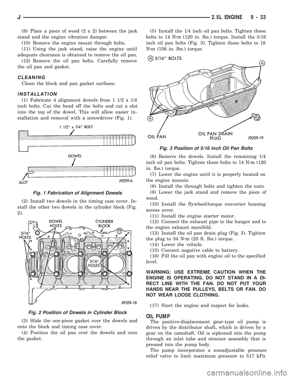
(1) Fabricate 4 alignment dowels from 1 1/2 x 1/4
inch bolts. Cut the head off the bolts and cut a slot
into the top of the dowel. This will allow easier in-
stallation and removal with a screwdriver (Fig. 1).
(2) Install two dowels in the timing case cover. In-
stall the other two dowels in the cylinder block (Fig.
2).
(3) Slide the one-piece gasket over the dowels and
onto the block and timing case cover.
(4) Position the oil pan over the dowels and onto
the gasket.(5) Install the 1/4 inch oil pan bolts. Tighten these
bolts to 14 Nzm (120 in. lbs.) torque. Install the 5/16
inch oil pan bolts (Fig. 3). Tighten these bolts to 18
Nzm (156 in. lbs.) torque.
(6) Remove the dowels. Install the remaining 1/4
inch oil pan bolts. Tighten these bolts to 14 Nzm (120
in. lbs.) torque.
(7) Lower the engine until it is properly located on
the engine mounts.
(8) Install the through bolts and tighten the nuts.
(9) Lower the jack stand and remove the piece of
wood.
(10) Install the flywheel/torque converter housing
access cover.
(11) Install the engine starter motor.
(12) Connect the exhaust pipe to the hanger and to
the engine exhaust manifold.
(13) Install the oil pan drain plug (Fig. 3). Tighten
the plug to 34 Nzm (25 ft. lbs.) torque.
(14) Lower the vehicle.
(15) Connect negative cable to battery.
(16) Fill the oil pan with engine oil to the specified
level.
WARNING: USE EXTREME CAUTION WHEN THE
ENGINE IS OPERATING. DO NOT STAND IN A DI-
RECT LINE WITH THE FAN. DO NOT PUT YOUR
HANDS NEAR THE PULLEYS, BELTS OR FAN. DO
NOT WEAR LOOSE CLOTHING.
(17) Start the engine and inspect for leaks.
OIL PUMP
The positive-displacement gear-type oil pump is
driven by the distributor shaft, which is driven by a
gear on the camshaft. Oil is siphoned into the pump
through an inlet tube and strainer assembly that is
pressed into the pump body.
The pump incorporates a nonadjustable pressure
relief valve to limit maximum pressure to 517 kPa
Fig. 1 Fabrication of Alignment Dowels
Fig. 2 Position of Dowels in Cylinder Block
Fig. 3 Position of 5/16 inch Oil Pan Bolts
J2.5L ENGINE 9 - 33
Page 897 of 1784
(29) Disconnect the engine speed sensor wire con-
nection.
(30) Remove the exhaust pipe support.
(31) Remove the flywheel/converter housing access
cover.
(32)Vehicles with Automatic Transmission:
(a) Mark the converter and drive plate location.
(b) Remove the converter-to-drive plate bolts.
(33) Remove the upper flywheel/converter housing
bolts and loosen the bottom bolts.
(34) Remove the engine mount cushion-to-engine
compartment bracket bolts.
(35) Lower the vehicle.
(36) Attach a lifting device to the engine.
(37) Raise the engine off the front supports.
(38) Place a support or floor jack under the con-
verter (or flywheel) housing.
(39) Remove the remaining converter (or flywheel)
housing bolts.
(40) Lift the engine out of the engine compart-
ment.
INSTALLATION
CAUTION: When installing the engine into a vehicle
equipped with an automatic transmission, be care-
ful not to damage the trigger wheel on the flywheel.
(1) Attach a lifting device to the engine and lower
the engine into the engine compartment. For easier
installation, it may be necessary to remove the en-
gine mount cushions from the engine mount bracket
as an aide in alignment of the engine to the trans-
mission.
(2)Vehicles with Manual Transmission:
(a) Insert the transmission shaft into the clutch
spline.
(b) Align the flywheel housing with the engine.
(c) Install and tighten the flywheel housing
lower bolts finger tight.(3)Vehicles with Automatic Transmission:
(a) Align the transmission torque converter
housing with the engine.
(b) Loosely install the converter housing lower
bolts and install the next higher bolt and nut on
each side.
(c) Tighten all 4 bolts finger tight.
(4) Install the engine mount cushions (if removed).
(5) Lower the engine and engine mount cushions
onto the engine compartment brackets. Install the
bolts and finger tighten the nuts.
(6) Remove the engine lifting device.
(7) Raise and support the vehicle.
(8) Install the remaining flywheel/converter hous-
ing bolts. Tighten all bolts to 38 Nzm (28 ft. lbs.)
torque.
(9)Vehicles with Automatic Transmission:
(a) Install the converter-to-drive plate bolts.
(b) Ensure the installation reference marks are
aligned.
(10) Install the flywheel/converter housing access
cover.
(11) Install the exhaust pipe support and tighten
the screw.
(12) Tighten the engine mount-to-bracket bolts.
(13) Connect the engine speed sensor wire connec-
tions and tighten the screws.
(14) Connect the exhaust pipe to the manifold.
(15) Install the starter motor and connect the ca-
ble.
(16) Connect the wires to the starter motor sole-
noid.
(17) Lower the vehicle.
(18) Connect all the vacuum hoses and wire con-
nectors identified during engine removal.
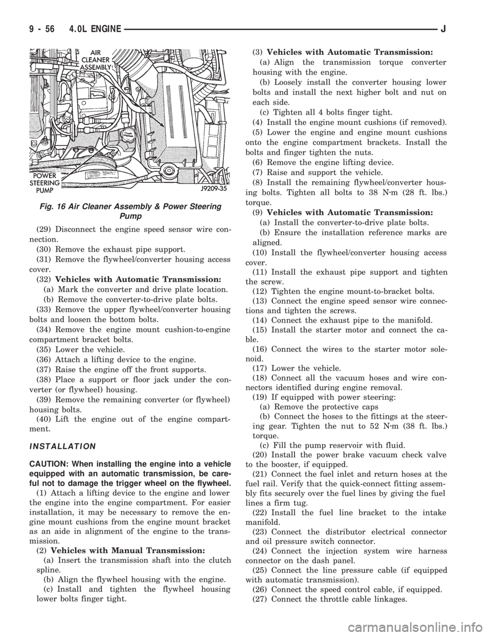
(19) If equipped with power steering:
(a) Remove the protective caps
(b) Connect the hoses to the fittings at the steer-
ing gear. Tighten the nut to 52 Nzm (38 ft. lbs.)
torque.
(c) Fill the pump reservoir with fluid.
(20) Install the power brake vacuum check valve
to the booster, if equipped.
(21) Connect the fuel inlet and return hoses at the
fuel rail. Verify that the quick-connect fitting assem-
bly fits securely over the fuel lines by giving the fuel
lines a firm tug.
(22) Install the fuel line bracket to the intake
manifold.
(23) Connect the distributor electrical connector
and oil pressure switch connector.
(24) Connect the injection system wire harness
connector on the dash panel.
(25) Connect the line pressure cable (if equipped
with automatic transmission).
(26) Connect the speed control cable, if equipped.
(27) Connect the throttle cable linkages.
Fig. 16 Air Cleaner Assembly & Power Steering
Pump
9 - 56 4.0L ENGINEJ
Page 899 of 1784
(20) Disconnect the coolant hoses from the rear of
the intake manifold and thermostat housing.
(21) Remove the fan shroud screws.
(22) Remove the radiator attaching bolts.
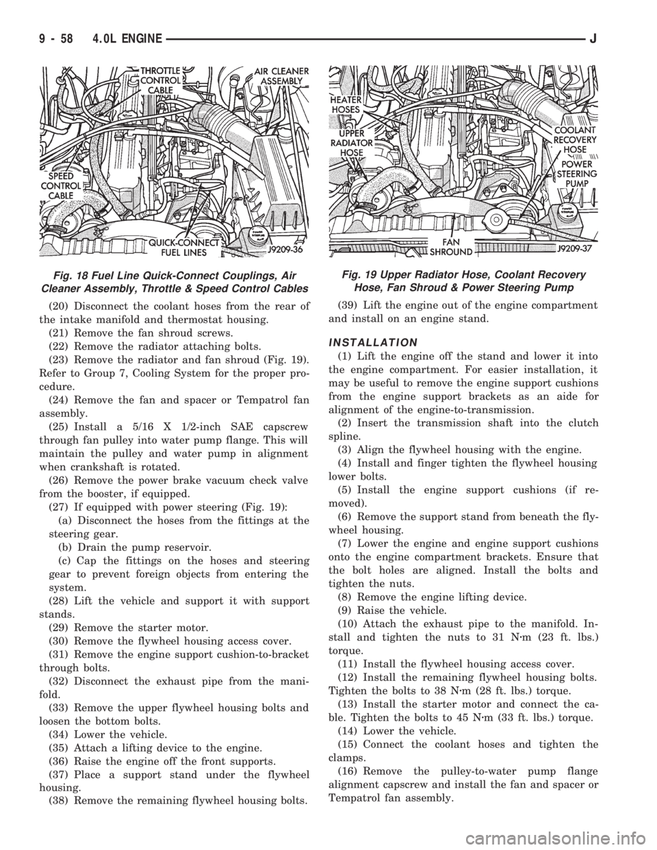
(23) Remove the radiator and fan shroud (Fig. 19).
Refer to Group 7, Cooling System for the proper pro-
cedure.
(24) Remove the fan and spacer or Tempatrol fan
assembly.
(25) Install a 5/16 X 1/2-inch SAE capscrew
through fan pulley into water pump flange. This will
maintain the pulley and water pump in alignment
when crankshaft is rotated.
(26) Remove the power brake vacuum check valve
from the booster, if equipped.
(27) If equipped with power steering (Fig. 19):
(a) Disconnect the hoses from the fittings at the
steering gear.
(b) Drain the pump reservoir.
(c) Cap the fittings on the hoses and steering
gear to prevent foreign objects from entering the
system.
(28) Lift the vehicle and support it with support
stands.
(29) Remove the starter motor.
(30) Remove the flywheel housing access cover.
(31) Remove the engine support cushion-to-bracket
through bolts.
(32) Disconnect the exhaust pipe from the mani-
fold.
(33) Remove the upper flywheel housing bolts and
loosen the bottom bolts.
(34) Lower the vehicle.
(35) Attach a lifting device to the engine.
(36) Raise the engine off the front supports.
(37) Place a support stand under the flywheel
housing.
(38) Remove the remaining flywheel housing bolts.(39) Lift the engine out of the engine compartment
and install on an engine stand.
INSTALLATION
(1) Lift the engine off the stand and lower it into
the engine compartment. For easier installation, it
may be useful to remove the engine support cushions
from the engine support brackets as an aide for
alignment of the engine-to-transmission.
(2) Insert the transmission shaft into the clutch
spline.
(3) Align the flywheel housing with the engine.
(4) Install and finger tighten the flywheel housing
lower bolts.
(5) Install the engine support cushions (if re-
moved).
(6) Remove the support stand from beneath the fly-
wheel housing.
(7) Lower the engine and engine support cushions
onto the engine compartment brackets. Ensure that
the bolt holes are aligned. Install the bolts and
tighten the nuts.
(8) Remove the engine lifting device.
(9) Raise the vehicle.
(10) Attach the exhaust pipe to the manifold. In-
stall and tighten the nuts to 31 Nzm (23 ft. lbs.)
torque.
(11) Install the flywheel housing access cover.
(12) Install the remaining flywheel housing bolts.
Tighten the bolts to 38 Nzm (28 ft. lbs.) torque.
(13) Install the starter motor and connect the ca-
ble. Tighten the bolts to 45 Nzm (33 ft. lbs.) torque.
(14) Lower the vehicle.
(15) Connect the coolant hoses and tighten the
clamps.
(16) Remove the pulley-to-water pump flange
alignment capscrew and install the fan and spacer or
Tempatrol fan assembly.
Fig. 18 Fuel Line Quick-Connect Couplings, Air
Cleaner Assembly, Throttle & Speed Control CablesFig. 19 Upper Radiator Hose, Coolant Recovery
Hose, Fan Shroud & Power Steering Pump
9 - 58 4.0L ENGINEJ
Page 913 of 1784
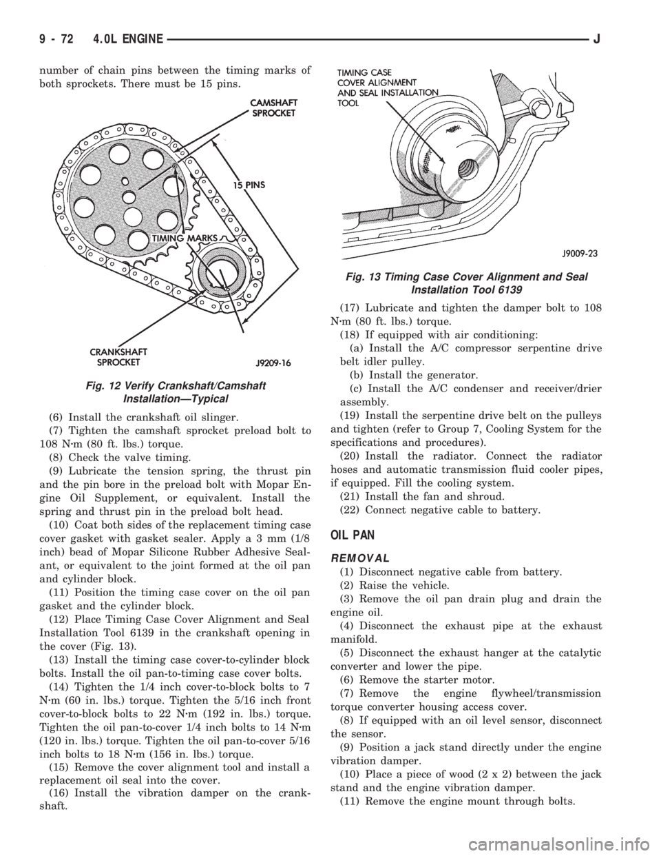
number of chain pins between the timing marks of
both sprockets. There must be 15 pins.
(6) Install the crankshaft oil slinger.
(7) Tighten the camshaft sprocket preload bolt to
108 Nzm (80 ft. lbs.) torque.
(8) Check the valve timing.
(9) Lubricate the tension spring, the thrust pin
and the pin bore in the preload bolt with Mopar En-
gine Oil Supplement, or equivalent. Install the
spring and thrust pin in the preload bolt head.
(10) Coat both sides of the replacement timing case
cover gasket with gasket sealer. Applya3mm(1/8
inch) bead of Mopar Silicone Rubber Adhesive Seal-
ant, or equivalent to the joint formed at the oil pan
and cylinder block.
(11) Position the timing case cover on the oil pan
gasket and the cylinder block.
(12) Place Timing Case Cover Alignment and Seal
Installation Tool 6139 in the crankshaft opening in
the cover (Fig. 13).
(13) Install the timing case cover-to-cylinder block
bolts. Install the oil pan-to-timing case cover bolts.
(14) Tighten the 1/4 inch cover-to-block bolts to 7
Nzm (60 in. lbs.) torque. Tighten the 5/16 inch front
cover-to-block bolts to 22 Nzm (192 in. lbs.) torque.
Tighten the oil pan-to-cover 1/4 inch bolts to 14 Nzm
(120 in. lbs.) torque. Tighten the oil pan-to-cover 5/16
inch bolts to 18 Nzm (156 in. lbs.) torque.
(15) Remove the cover alignment tool and install a
replacement oil seal into the cover.
(16) Install the vibration damper on the crank-
shaft.(17) Lubricate and tighten the damper bolt to 108
Nzm (80 ft. lbs.) torque.
(18) If equipped with air conditioning:
(a) Install the A/C compressor serpentine drive
belt idler pulley.
(b) Install the generator.
(c) Install the A/C condenser and receiver/drier
assembly.
(19) Install the serpentine drive belt on the pulleys
and tighten (refer to Group 7, Cooling System for the
specifications and procedures).
(20) Install the radiator. Connect the radiator
hoses and automatic transmission fluid cooler pipes,
if equipped. Fill the cooling system.
(21) Install the fan and shroud.
(22) Connect negative cable to battery.
OIL PAN
REMOVAL
(1) Disconnect negative cable from battery.
(2) Raise the vehicle.
(3) Remove the oil pan drain plug and drain the
engine oil.
(4) Disconnect the exhaust pipe at the exhaust
manifold.
(5) Disconnect the exhaust hanger at the catalytic
converter and lower the pipe.
(6) Remove the starter motor.
(7) Remove the engine flywheel/transmission
torque converter housing access cover.
(8) If equipped with an oil level sensor, disconnect
the sensor.
(9) Position a jack stand directly under the engine
vibration damper.
(10) Place a piece of wood (2 x 2) between the jack
stand and the engine vibration damper.
(11) Remove the engine mount through bolts.
Fig. 12 Verify Crankshaft/Camshaft
InstallationÐTypical
Fig. 13 Timing Case Cover Alignment and Seal
Installation Tool 6139
9 - 72 4.0L ENGINEJ
Page 914 of 1784
(12) Using the jack stand, raise the engine until
adequate clearance is obtained to remove the oil pan.
(13) Remove the oil pan bolts. Carefully slide the
oil pan and gasket to the rear. If equipped with an
oil level sensor, take care not to damage the sensor.
CLEANING
Clean the block and pan gasket surfaces.
INSTALLATION
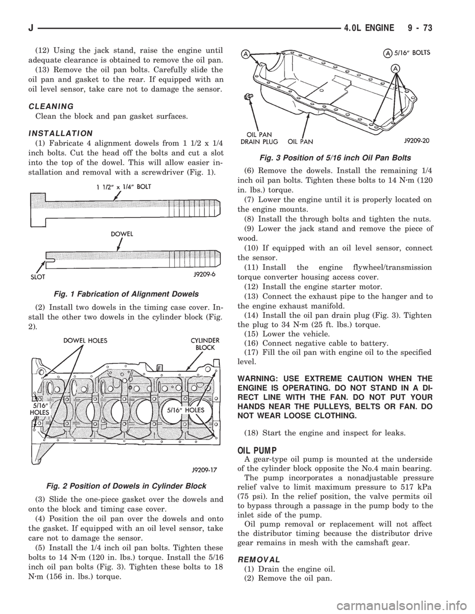
(1) Fabricate 4 alignment dowels from 1 1/2 x 1/4
inch bolts. Cut the head off the bolts and cut a slot
into the top of the dowel. This will allow easier in-
stallation and removal with a screwdriver (Fig. 1).
(2) Install two dowels in the timing case cover. In-
stall the other two dowels in the cylinder block (Fig.
2).
(3) Slide the one-piece gasket over the dowels and
onto the block and timing case cover.
(4) Position the oil pan over the dowels and onto
the gasket. If equipped with an oil level sensor, take
care not to damage the sensor.
(5) Install the 1/4 inch oil pan bolts. Tighten these
bolts to 14 Nzm (120 in. lbs.) torque. Install the 5/16
inch oil pan bolts (Fig. 3). Tighten these bolts to 18
Nzm (156 in. lbs.) torque.(6) Remove the dowels. Install the remaining 1/4
inch oil pan bolts. Tighten these bolts to 14 Nzm (120
in. lbs.) torque.
(7) Lower the engine until it is properly located on
the engine mounts.
(8) Install the through bolts and tighten the nuts.
(9) Lower the jack stand and remove the piece of
wood.
(10) If equipped with an oil level sensor, connect
the sensor.
(11) Install the engine flywheel/transmission
torque converter housing access cover.
(12) Install the engine starter motor.
(13) Connect the exhaust pipe to the hanger and to
the engine exhaust manifold.
(14) Install the oil pan drain plug (Fig. 3). Tighten
the plug to 34 Nzm (25 ft. lbs.) torque.
(15) Lower the vehicle.
(16) Connect negative cable to battery.
(17) Fill the oil pan with engine oil to the specified
level.
WARNING: USE EXTREME CAUTION WHEN THE
ENGINE IS OPERATING. DO NOT STAND IN A DI-
RECT LINE WITH THE FAN. DO NOT PUT YOUR
HANDS NEAR THE PULLEYS, BELTS OR FAN. DO
NOT WEAR LOOSE CLOTHING.
(18) Start the engine and inspect for leaks.
OIL PUMP
A gear-type oil pump is mounted at the underside
of the cylinder block opposite the No.4 main bearing.
The pump incorporates a nonadjustable pressure
relief valve to limit maximum pressure to 517 kPa
(75 psi). In the relief position, the valve permits oil
to bypass through a passage in the pump body to the
inlet side of the pump.
Oil pump removal or replacement will not affect
the distributor timing because the distributor drive
gear remains in mesh with the camshaft gear.
REMOVAL
(1) Drain the engine oil.
(2) Remove the oil pan.
Fig. 1 Fabrication of Alignment Dowels
Fig. 2 Position of Dowels in Cylinder Block
Fig. 3 Position of 5/16 inch Oil Pan Bolts
J4.0L ENGINE 9 - 73
Page 1028 of 1784
²Have a 3 degree maximum operating angle
²Have at least a 1/2 degree continuous operating
(propeller shaft) angle
Engine speed (R.P.M.) is the main factor though in
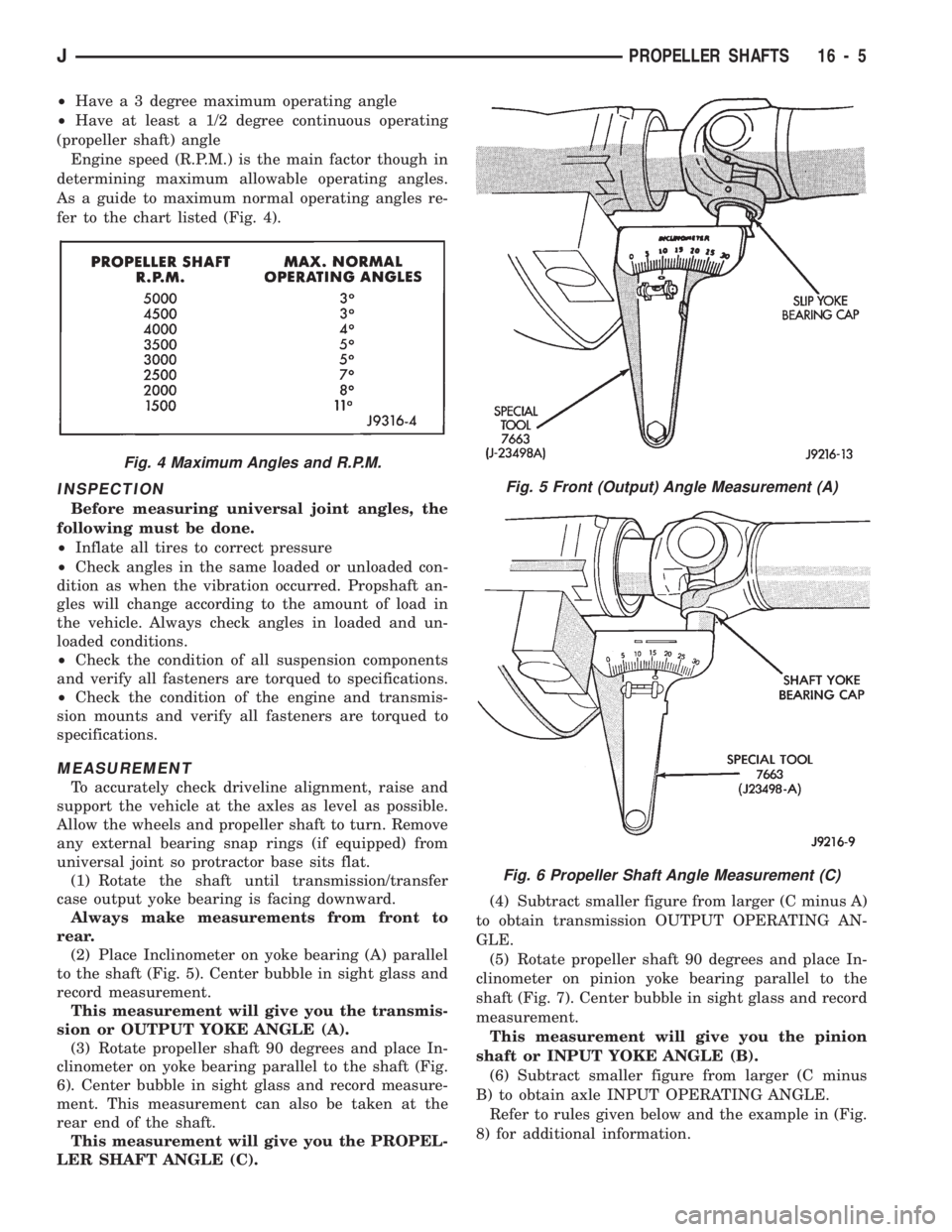
determining maximum allowable operating angles.
As a guide to maximum normal operating angles re-
fer to the chart listed (Fig. 4).
INSPECTION
Before measuring universal joint angles, the
following must be done.
²Inflate all tires to correct pressure
²Check angles in the same loaded or unloaded con-
dition as when the vibration occurred. Propshaft an-
gles will change according to the amount of load in
the vehicle. Always check angles in loaded and un-
loaded conditions.
²Check the condition of all suspension components
and verify all fasteners are torqued to specifications.
²Check the condition of the engine and transmis-
sion mounts and verify all fasteners are torqued to
specifications.
MEASUREMENT
To accurately check driveline alignment, raise and
support the vehicle at the axles as level as possible.
Allow the wheels and propeller shaft to turn. Remove
any external bearing snap rings (if equipped) from
universal joint so protractor base sits flat.
(1) Rotate the shaft until transmission/transfer
case output yoke bearing is facing downward.
Always make measurements from front to
rear.
(2) Place Inclinometer on yoke bearing (A) parallel
to the shaft (Fig. 5). Center bubble in sight glass and
record measurement.
This measurement will give you the transmis-
sion or OUTPUT YOKE ANGLE (A).
(3) Rotate propeller shaft 90 degrees and place In-
clinometer on yoke bearing parallel to the shaft (Fig.
6). Center bubble in sight glass and record measure-
ment. This measurement can also be taken at the
rear end of the shaft.
This measurement will give you the PROPEL-
LER SHAFT ANGLE (C).(4) Subtract smaller figure from larger (C minus A)
to obtain transmission OUTPUT OPERATING AN-
GLE.
(5) Rotate propeller shaft 90 degrees and place In-
clinometer on pinion yoke bearing parallel to the
shaft (Fig. 7). Center bubble in sight glass and record
measurement.
This measurement will give you the pinion
shaft or INPUT YOKE ANGLE (B).
(6) Subtract smaller figure from larger (C minus
B) to obtain axle INPUT OPERATING ANGLE.
Refer to rules given below and the example in (Fig.
8) for additional information.
Fig. 4 Maximum Angles and R.P.M.
Fig. 5 Front (Output) Angle Measurement (A)
Fig. 6 Propeller Shaft Angle Measurement (C)
JPROPELLER SHAFTS 16 - 5
Page 1051 of 1784
STEERING LINKAGEÐXJ
INDEX
page page
Drag Link.............................. 14
Pitman Arm............................. 15
Service Information....................... 14Steering Dampener....................... 15
Tie Rod ................................ 14
SERVICE INFORMATION
The steering linkage consists of a pitman arm, drag
link, tie rod, and steering dampener. Adjustment
sleeves are used on the tie rod and drag link for toe
and steering wheel alignment.
Refer to Group 2, Front Suspension and Axle for
additional information.
The tie-rod end ball stud seals should be inspected
during all oil changes.
A damaged ball stud seal requires removal of the
seal. Inspect the tie-rod end ball stud at the throat
opening. Check for lubricant loss, contamination, ball
stud wear or corrosion. If these conditions exist, re-
place the tie-rod. A replacement seal can be installed
if lubricant is in good condition. Otherwise, a com-
plete replacement ball stud end should be installed.
Lubricate the tie-rod end with MOPARtMulti-Mile-
age Lubricant, or equivalent product.
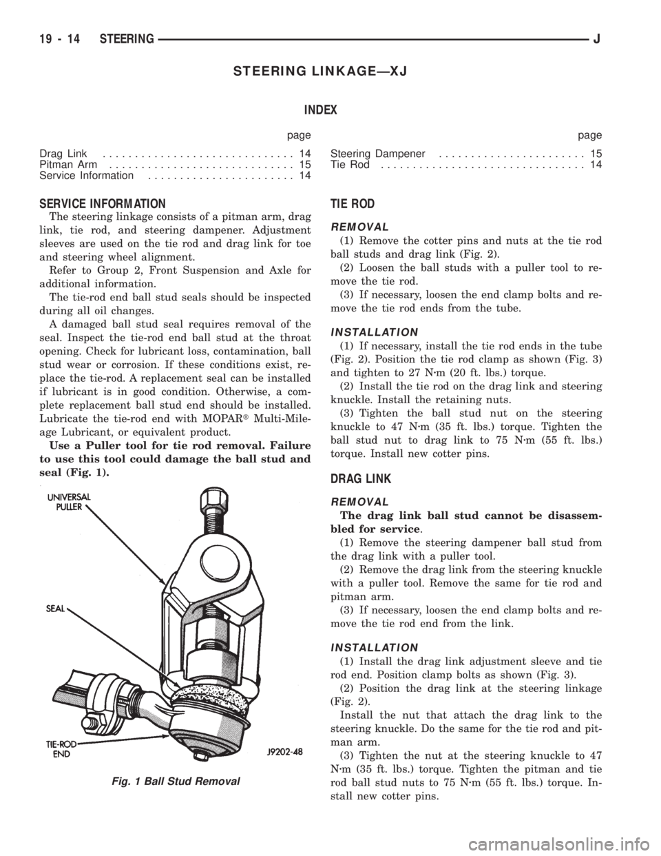
Use a Puller tool for tie rod removal. Failure
to use this tool could damage the ball stud and
seal (Fig. 1).
TIE ROD
REMOVAL
(1) Remove the cotter pins and nuts at the tie rod
ball studs and drag link (Fig. 2).
(2) Loosen the ball studs with a puller tool to re-
move the tie rod.
(3) If necessary, loosen the end clamp bolts and re-
move the tie rod ends from the tube.
INSTALLATION
(1) If necessary, install the tie rod ends in the tube
(Fig. 2). Position the tie rod clamp as shown (Fig. 3)
and tighten to 27 Nzm (20 ft. lbs.) torque.
(2) Install the tie rod on the drag link and steering
knuckle. Install the retaining nuts.
(3) Tighten the ball stud nut on the steering
knuckle to 47 Nzm (35 ft. lbs.) torque. Tighten the
ball stud nut to drag link to 75 Nzm (55 ft. lbs.)
torque. Install new cotter pins.
DRAG LINK
REMOVAL
The drag link ball stud cannot be disassem-
bled for service.
(1) Remove the steering dampener ball stud from
the drag link with a puller tool.
(2) Remove the drag link from the steering knuckle
with a puller tool. Remove the same for tie rod and
pitman arm.
(3) If necessary, loosen the end clamp bolts and re-
move the tie rod end from the link.
INSTALLATION
(1) Install the drag link adjustment sleeve and tie
rod end. Position clamp bolts as shown (Fig. 3).
(2) Position the drag link at the steering linkage
(Fig. 2).
Install the nut that attach the drag link to the
steering knuckle. Do the same for the tie rod and pit-
man arm.
(3) Tighten the nut at the steering knuckle to 47
Nzm (35 ft. lbs.) torque. Tighten the pitman and tie
rod ball stud nuts to 75 Nzm (55 ft. lbs.) torque. In-
stall new cotter pins.
Fig. 1 Ball Stud Removal
19 - 14 STEERINGJ
Page 1054 of 1784
STEERING LINKAGEÐYJ
INDEX
page page
Drag Link.............................. 17
Pitman Arm............................. 18
Service Information....................... 17Steering Dampener....................... 18
Tie Rod ................................ 17
SERVICE INFORMATION
The steering linkage consists of a pitman arm, drag
link, tie rod, and steering dampener. Adjustment
sleeves are used on the tie rod and drag link for toe
and steering wheel alignment.
Refer to Group 2, Front Suspension and Axle for
additional information.
The tie-rod end ball stud seals should be inspected
during all oil changes.
A damaged ball stud seal requires removal of the
seal. Inspect the tie-rod end ball stud at the throat
opening. Check for lubricant loss, contamination, ball
stud wear or corrosion. If these conditions exist, re-
place the tie-rod. A replacement seal can be installed
if lubricant is in good condition. Otherwise, a com-
plete replacement ball stud end should be installed.
Lubricate the tie-rod end with MOPARtMulti-Mile-
age Lubricant, or equivalent product.
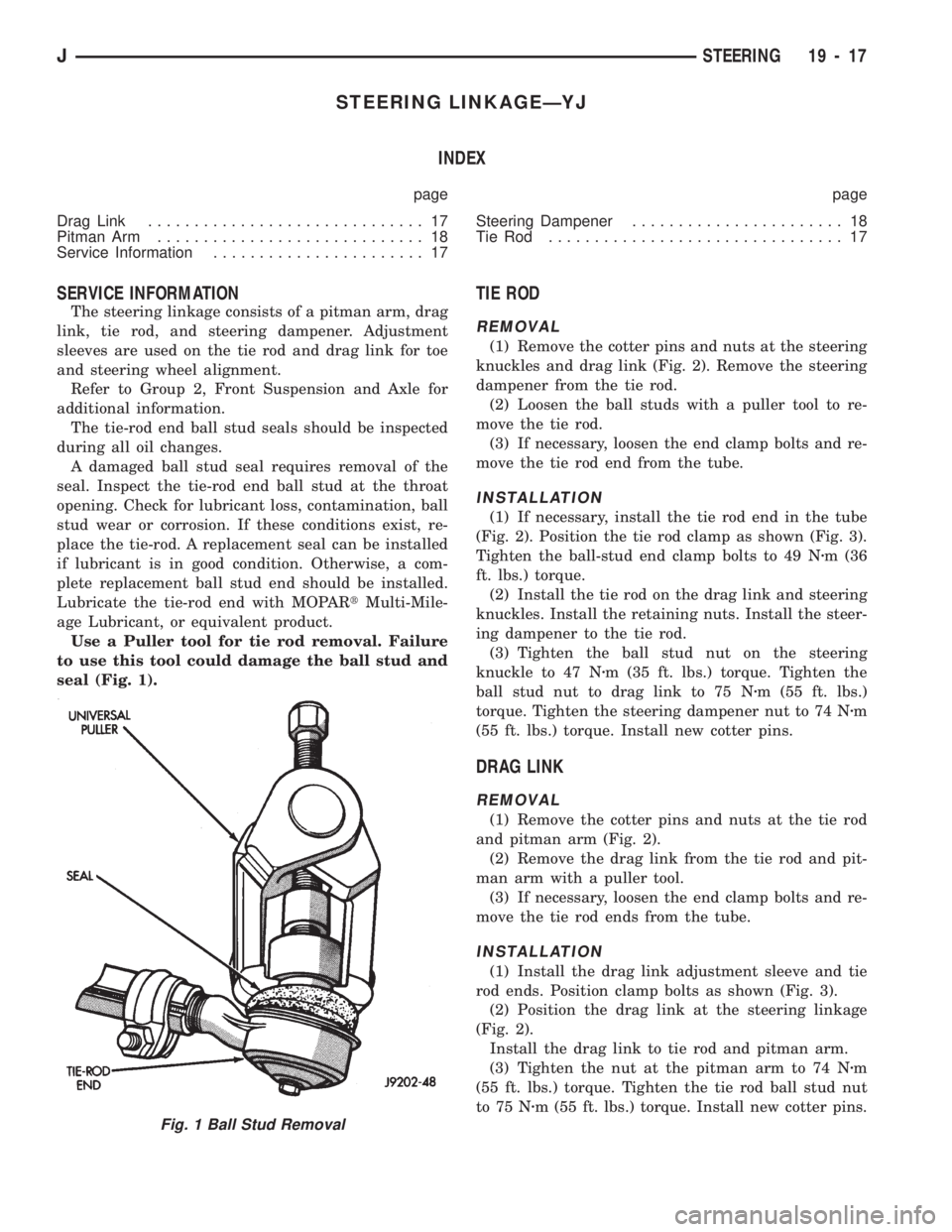
Use a Puller tool for tie rod removal. Failure
to use this tool could damage the ball stud and
seal (Fig. 1).
TIE ROD
REMOVAL
(1) Remove the cotter pins and nuts at the steering
knuckles and drag link (Fig. 2). Remove the steering
dampener from the tie rod.
(2) Loosen the ball studs with a puller tool to re-
move the tie rod.
(3) If necessary, loosen the end clamp bolts and re-
move the tie rod end from the tube.
INSTALLATION
(1) If necessary, install the tie rod end in the tube
(Fig. 2). Position the tie rod clamp as shown (Fig. 3).
Tighten the ball-stud end clamp bolts to 49 Nzm (36
ft. lbs.) torque.
(2) Install the tie rod on the drag link and steering
knuckles. Install the retaining nuts. Install the steer-
ing dampener to the tie rod.
(3) Tighten the ball stud nut on the steering
knuckle to 47 Nzm (35 ft. lbs.) torque. Tighten the
ball stud nut to drag link to 75 Nzm (55 ft. lbs.)
torque. Tighten the steering dampener nut to 74 Nzm
(55 ft. lbs.) torque. Install new cotter pins.
DRAG LINK
REMOVAL
(1) Remove the cotter pins and nuts at the tie rod
and pitman arm (Fig. 2).
(2) Remove the drag link from the tie rod and pit-
man arm with a puller tool.
(3) If necessary, loosen the end clamp bolts and re-
move the tie rod ends from the tube.
INSTALLATION
(1) Install the drag link adjustment sleeve and tie
rod ends. Position clamp bolts as shown (Fig. 3).
(2) Position the drag link at the steering linkage
(Fig. 2).
Install the drag link to tie rod and pitman arm.
(3) Tighten the nut at the pitman arm to 74 Nzm
(55 ft. lbs.) torque. Tighten the tie rod ball stud nut
to 75 Nzm (55 ft. lbs.) torque. Install new cotter pins.
Fig. 1 Ball Stud Removal
JSTEERING 19 - 17