1994 JEEP CHEROKEE Starter
[x] Cancel search: StarterPage 325 of 1784
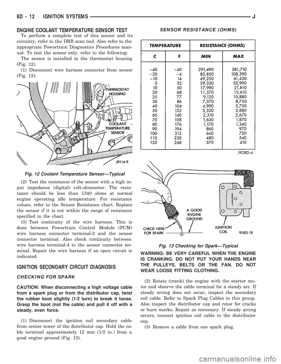
ENGINE COOLANT TEMPERATURE SENSOR TEST
To perform a complete test of this sensor and its
circuitry, refer to the DRB scan tool. Also refer to the
appropriate Powertrain Diagnostics Procedures man-
ual. To test the sensor only, refer to the following:
The sensor is installed in the thermostat housing
(Fig. 12).
(1) Disconnect wire harness connector from sensor
(Fig. 12).
(2) Test the resistance of the sensor with a high in-
put impedance (digital) volt-ohmmeter. The resis-
tance should be less than 1340 ohms at normal
engine operating idle temperature. For resistance
values, refer to the Sensor Resistance chart. Replace
the sensor if it is not within the range of resistance
specified in the chart.
(3) Test continuity of the wire harness. This is
done between Powertrain Control Module (PCM)
wire harness connector terminal-2 and the sensor
connector terminal. Also check continuity between
wire harness terminal-4 to the sensor connector ter-
minal. Repair the wire harness if an open circuit is
indicated.
IGNITION SECONDARY CIRCUIT DIAGNOSIS
CHECKING FOR SPARK
CAUTION: When disconnecting a high voltage cable
from a spark plug or from the distributor cap, twist
the rubber boot slightly (1/2 turn) to break it loose.
Grasp the boot (not the cable) and pull it off with a
steady, even force.
(1) Disconnect the ignition coil secondary cable
from center tower of the distributor cap. Hold the ca-
ble terminal approximately 12 mm (1/2 in.) from a
good engine ground (Fig. 13).WARNING: BE VERY CAREFUL WHEN THE ENGINE
IS CRANKING. DO NOT PUT YOUR HANDS NEAR
THE PULLEYS, BELTS OR THE FAN. DO NOT
WEAR LOOSE FITTING CLOTHING.
(2) Rotate (crank) the engine with the starter mo-
tor and observe the cable terminal for a steady arc. If
steady arcing does not occur, inspect the secondary
coil cable. Refer to Spark Plug Cables in this group.
Also inspect the distributor cap and rotor for cracks
or burn marks. Repair as necessary. If steady arcing
occurs, connect ignition coil cable to the distributor
cap.
(3) Remove a cable from one spark plug.
Fig. 12 Coolant Temperature SensorÐTypical
SENSOR RESISTANCE (OHMS)
Fig. 13 Checking for SparkÐTypical
8D - 12 IGNITION SYSTEMSJ
Page 326 of 1784
(4) Using insulated pliers, hold the cable terminal
approximately 12 mm (1/2 in.) from the engine cylin-
der head or block while rotating the engine with the
starter motor. Observe the spark plug cable terminal
for an arc. If steady arcing occurs, it can be expected
that the ignition secondary system is operating cor-
rectly. If steady arcing occurs at the spark plug ca-
bles, but the engine will not start, connect the DRB
scan tool. Refer to the Powertrain Diagnostic Proce-
dures service manual for DRB operation.
FAILURE TO START TEST
To prevent unnecessary diagnostic time and wrong
test results, the previous Checking For Spark test
should be performed prior to this test.
WARNING: SET PARKING BRAKE OR BLOCK THE
DRIVE WHEELS BEFORE PROCEEDING WITH THIS
TEST.
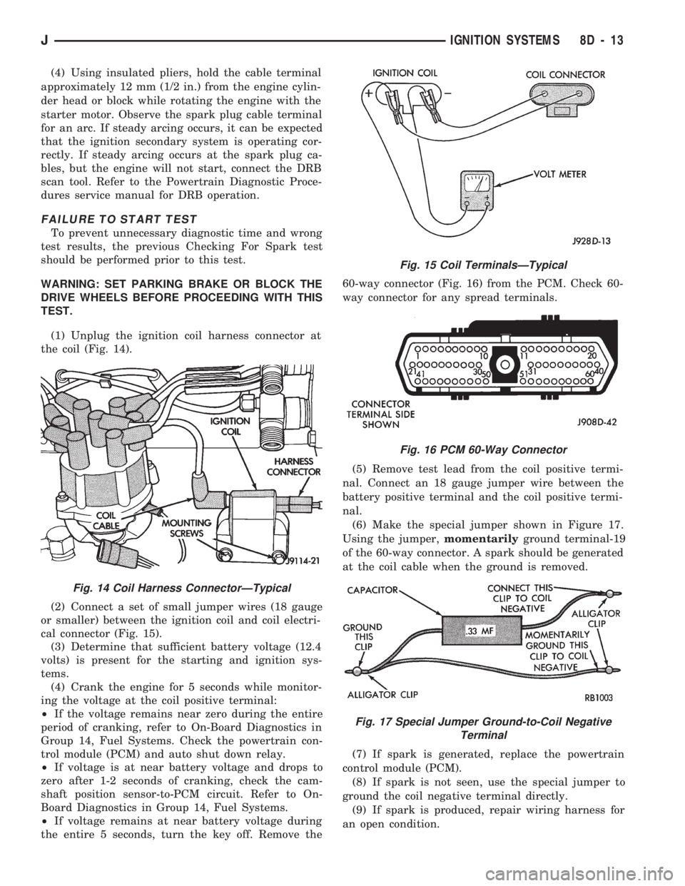
(1) Unplug the ignition coil harness connector at
the coil (Fig. 14).
(2) Connect a set of small jumper wires (18 gauge
or smaller) between the ignition coil and coil electri-
cal connector (Fig. 15).
(3) Determine that sufficient battery voltage (12.4
volts) is present for the starting and ignition sys-
tems.
(4) Crank the engine for 5 seconds while monitor-
ing the voltage at the coil positive terminal:
²If the voltage remains near zero during the entire
period of cranking, refer to On-Board Diagnostics in
Group 14, Fuel Systems. Check the powertrain con-
trol module (PCM) and auto shut down relay.
²If voltage is at near battery voltage and drops to
zero after 1-2 seconds of cranking, check the cam-
shaft position sensor-to-PCM circuit. Refer to On-
Board Diagnostics in Group 14, Fuel Systems.
²If voltage remains at near battery voltage during
the entire 5 seconds, turn the key off. Remove the60-way connector (Fig. 16) from the PCM. Check 60-
way connector for any spread terminals.
(5) Remove test lead from the coil positive termi-
nal. Connect an 18 gauge jumper wire between the
battery positive terminal and the coil positive termi-
nal.
(6) Make the special jumper shown in Figure 17.
Using the jumper,momentarilyground terminal-19
of the 60-way connector. A spark should be generated
at the coil cable when the ground is removed.
(7) If spark is generated, replace the powertrain
control module (PCM).
(8) If spark is not seen, use the special jumper to
ground the coil negative terminal directly.
(9) If spark is produced, repair wiring harness for
an open condition.
Fig. 14 Coil Harness ConnectorÐTypical
Fig. 15 Coil TerminalsÐTypical
Fig. 16 PCM 60-Way Connector
Fig. 17 Special Jumper Ground-to-Coil Negative
Terminal
JIGNITION SYSTEMS 8D - 13
Page 506 of 1784
WIRING AND COMPONENT IDENTIFICATION
CONTENTS
page page
XJ ................................... 25
XJ RHD ............................... 43YJ ................................... 13
The wiring and components shown in this section
are divided into sections by vehicle line. When locat-
ing a specific wire routing or component, first turn to
the appropriate index, then look up thefigure num-
berthat refers to the component.Page numbers at
the top of the page do not refer to figure num-
bers.
YJ
Caption Fig.
Battery and Starter Wiring.......................8
Body Wiring...............................1,2
Chassis Wiring...............................3
Engine Compartment Wiring......................7
Engine Wiring 2.5L...........................10Caption Fig.
Engine Wiring 4.0L...........................11
Front End Wiring.............................12
Instrument Panel Wiring.......................5,6
Steering Column Wiring.........................4
Transmission Wiring...........................9
JWIRING AND COMPONENT IDENTIFICATION 8W - 13
Page 513 of 1784
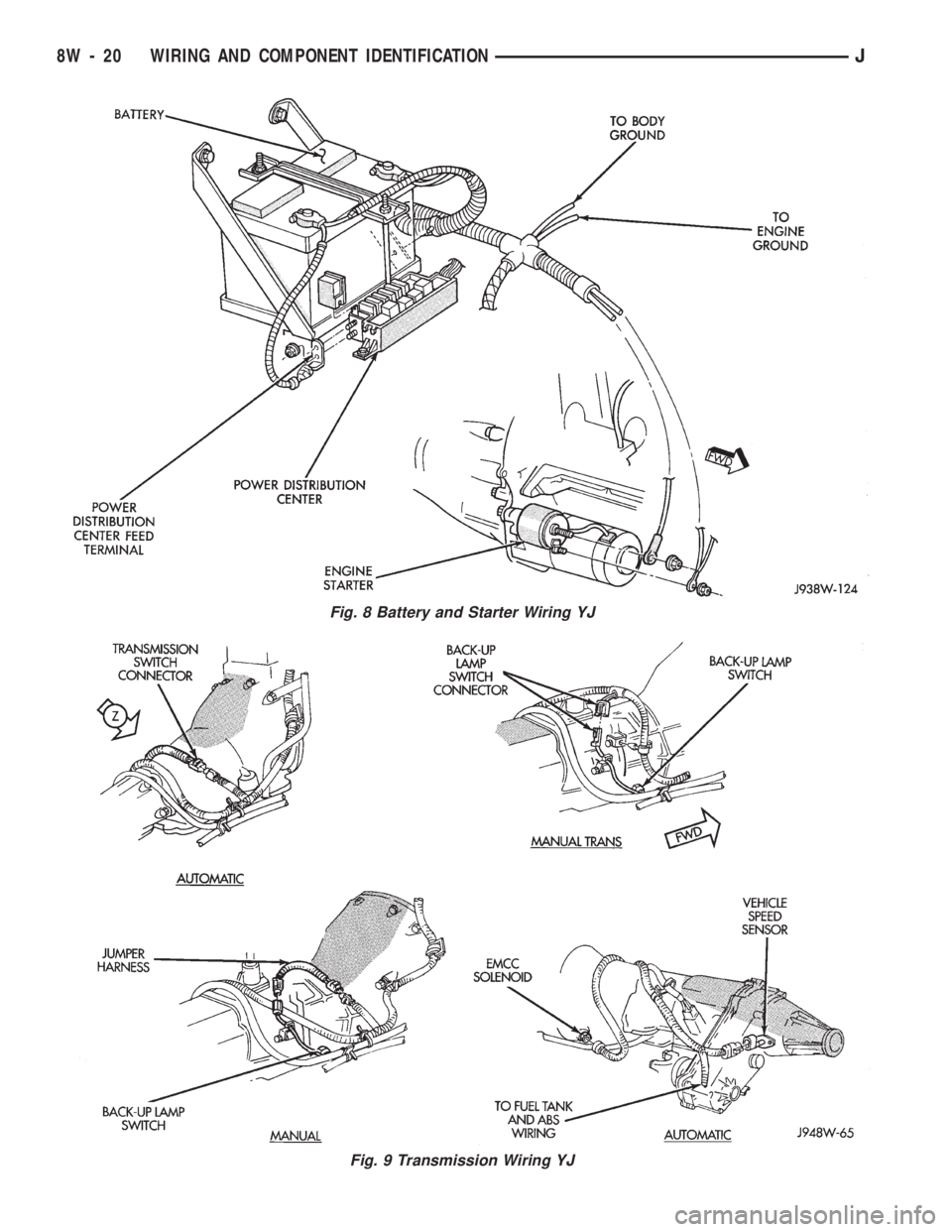
Fig. 8 Battery and Starter Wiring YJ
Fig. 9 Transmission Wiring YJ
8W - 20 WIRING AND COMPONENT IDENTIFICATIONJ
Page 566 of 1784
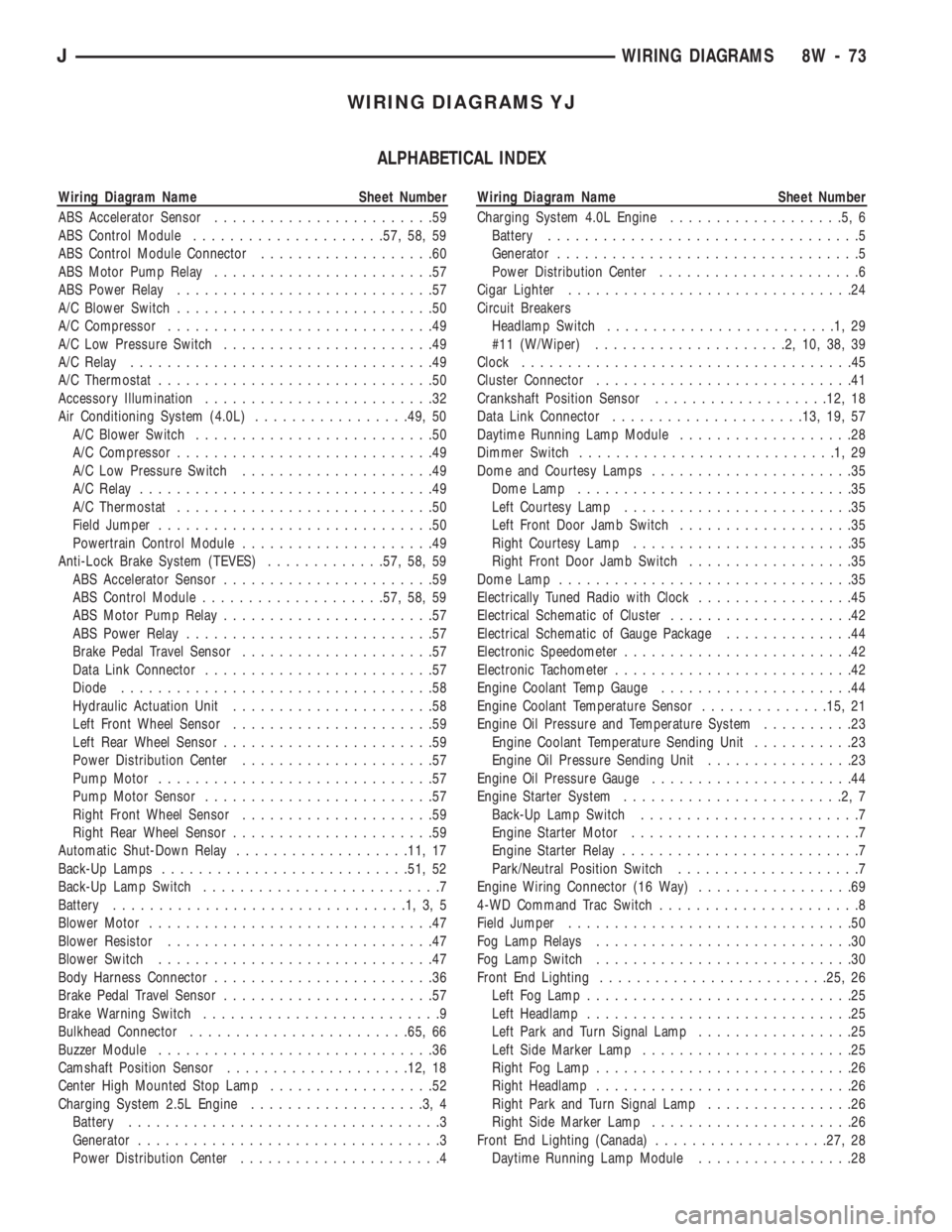
WIRING DIAGRAMS YJ
ALPHABETICAL INDEX
Wiring Diagram Name Sheet Number
ABS Accelerator Sensor........................59
ABS Control Module.....................57, 58, 59
ABS Control Module Connector...................60
ABS Motor Pump Relay........................57
ABS Power Relay............................57
A/C Blower Switch............................50
A/C Compressor.............................49
A/C Low Pressure Switch.......................49
A/C Relay.................................49
A/C Thermostat..............................50
Accessory Illumination.........................32
Air Conditioning System (4.0L).................49, 50
A/C Blower Switch..........................50
A/C Compressor............................49
A/C Low Pressure Switch.....................49
A/C Relay................................49
A/C Thermostat............................50
Field Jumper..............................50
Powertrain Control Module.....................49
Anti-Lock Brake System (TEVES).............57, 58, 59
ABS Accelerator Sensor.......................59
ABS Control Module....................57, 58, 59
ABS Motor Pump Relay.......................57
ABS Power Relay...........................57
Brake Pedal Travel Sensor.....................57
Data Link Connector.........................57
Diode..................................58
Hydraulic Actuation Unit......................58
Left Front Wheel Sensor......................59
Left Rear Wheel Sensor.......................59
Power Distribution Center.....................57
Pump Motor..............................57
Pump Motor Sensor.........................57
Right Front Wheel Sensor.....................59
Right Rear Wheel Sensor......................59
Automatic Shut-Down Relay...................11, 17
Back-Up Lamps...........................51, 52
Back-Up Lamp Switch..........................7
Battery................................1,3,5
Blower Motor...............................47
Blower Resistor.............................47
Blower Switch..............................47
Body Harness Connector........................36
Brake Pedal Travel Sensor.......................57
Brake Warning Switch..........................9
Bulkhead Connector........................65, 66
Buzzer Module..............................36
Camshaft Position Sensor....................12, 18
Center High Mounted Stop Lamp..................52
Charging System 2.5L Engine...................3,4
Battery..................................3
Generator.................................3
Power Distribution Center......................4Wiring Diagram Name Sheet Number
Charging System 4.0L Engine...................5,6
Battery..................................5
Generator.................................5
Power Distribution Center......................6
Cigar Lighter...............................24
Circuit Breakers
Headlamp Switch.........................1,29
#11 (W/Wiper).....................2,10,38,39
Clock....................................45
Cluster Connector............................41
Crankshaft Position Sensor...................12, 18
Data Link Connector.....................13, 19, 57
Daytime Running Lamp Module...................28
Dimmer Switch............................1,29
Dome and Courtesy Lamps......................35
Dome Lamp..............................35
Left Courtesy Lamp.........................35
Left Front Door Jamb Switch...................35
Right Courtesy Lamp........................35
Right Front Door Jamb Switch..................35
Dome Lamp................................35
Electrically Tuned Radio with Clock.................45
Electrical Schematic of Cluster....................42
Electrical Schematic of Gauge Package..............44
Electronic Speedometer.........................42
Electronic Tachometer..........................42
Engine Coolant Temp Gauge.....................44
Engine Coolant Temperature Sensor..............15, 21
Engine Oil Pressure and Temperature System..........23
Engine Coolant Temperature Sending Unit...........23
Engine Oil Pressure Sending Unit................23
Engine Oil Pressure Gauge......................44
Engine Starter System........................2,7
Back-Up Lamp Switch........................7
Engine Starter Motor.........................7
Engine Starter Relay..........................7
Park/Neutral Position Switch....................7
Engine Wiring Connector (16 Way).................69
4-WD Command Trac Switch......................8
Field Jumper...............................50
Fog Lamp Relays............................30
Fog Lamp Switch............................30
Front End Lighting.........................25, 26
Left Fog Lamp.............................25
Left Headlamp.............................25
Left Park and Turn Signal Lamp.................25
Left Side Marker Lamp.......................25
Right Fog Lamp............................26
Right Headlamp............................26
Right Park and Turn Signal Lamp................26
Right Side Marker Lamp......................26
Front End Lighting (Canada)...................27, 28
Daytime Running Lamp Module.................28
JWIRING DIAGRAMS 8W - 73
Page 568 of 1784
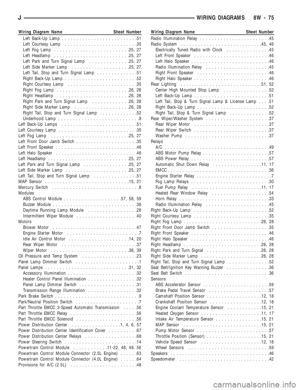
Wiring Diagram Name Sheet Number
Left Back-Up Lamp..........................51
Left Courtesy Lamp.........................35
Left Fog Lamp..........................25, 27
Left Headlamp..........................25, 27
Left Park and Turn Signal Lamp..............25, 27
Left Side Marker Lamp....................25, 27
Left Tail, Stop and Turn Signal Lamp..............51
Right Back-Up Lamp.........................52
Right Courtesy Lamp........................35
Right Fog Lamp.........................26, 28
Right Headlamp.........................26, 28
Right Park and Turn Signal Lamp.............26, 28
Right Side Marker Lamp...................26, 28
Right Tail, Stop and Turn Signal Lamp.............52
Underhood Lamp............................8
Left Back-Up Lamps..........................51
Left Courtesy Lamp...........................35
Left Fog Lamp...........................25, 27
Left Front Door Jamb Switch.....................35
Left Front Speaker............................46
Left Halo Speaker............................46
Left Headlamp............................25, 27
Left Park and Turn Signal Lamp................25, 27
Left Side Marker Lamp......................25, 27
Left Tail, Stop and Turn Signal Lamp...............51
MAP Sensor.............................15, 21
Mercury Switch..............................8
Modules
ABS Control Module....................57, 58, 59
Buzzer Module.............................36
Daytime Running Lamp Module.................28
Intermittent Wiper Module.....................40
Motors
Blower Motor.............................47
Engine Starter Motor.........................7
Idle Air Control Motor.....................14, 20
Rear Wiper Motor..........................37
Wiper Motor...........................38, 39
Oil Pressure and Temp System...................23
Panel Lamp Dimmer Switch......................1
Panel Lamps.............................31, 32
Accessory Illumination........................32
Heater Control Panel Illumination.................32
Panel Lamp Dimmer Switch....................31
Transmission Range Illumination.................32
Park Brake Switch.............................9
Park/Neutral Position Switch......................7
Part Throttle EMCC 3-Speed Automatic Transmission.....56
Part Throttle EMCC Relay.......................56
Part Throttle EMCC Solenoid.....................56
Power Distribution Center.................1,4,6,57
Power Distribution Center Identification Cover..........67
Power Distribution Center Relays..................68
Power Steering Switch.........................14
Powertrain Control Module............11-22, 48, 49, 56
Powertrain Control Module Connector (2.5L Engine)......63
Powertrain Control Module Connector (4.0L Engine)......64
Provisions for A/C (2.5L).......................48Wiring Diagram Name Sheet Number
Radio Illumination Relay........................45
Radio System............................45, 46
Electrically Tuned Radio with Clock...............45
Left Front Speaker..........................46
Left Halo Speaker...........................46
Radio Illumination Relay......................45
Right Front Speaker.........................46
Right Halo Speaker..........................46
Rear Lighting............................51, 52
Center High Mounted Stop Lamp................52
Left Back-Up Lamp..........................51
Left Tail, Stop & Turn Signal Lamp & License Lamp....51
Right Back-Up Lamp.........................52
Right Tail, Stop & Turn Signal Lamp..............52
Rear Wiper/Washer System......................37
Rear Wiper Motor..........................37
Rear Wiper Switch..........................37
Washer Pump.............................37
Relays
A/C ....................................49
ABS Motor Pump Relay.......................57
ABS Power Relay...........................57
Automatic Shut Down Relay.................11, 17
EMCC...................................56
Engine Starter Relay..........................7
Fog Lamp Relays...........................30
Fuel Pump Relay........................11, 17
Heated Rear Window Relay....................54
Horn Relay...............................33
Radio Illumination Relay......................45
Right Back-Up Lamp..........................52
Right Courtesy Lamp..........................35
Right Fog Lamp...........................26, 28
Right Front Door Jamb Switch....................35
Right Front Speaker...........................46
Right Halo Speaker...........................46
Right Headlamp...........................26, 28
Right Park and Turn Signal...................26, 28
Right Side Marker Lamp.....................26, 28
Right Tail, Stop and Turn Signal Lamp..............52
Seat Belt/Ignition Key Warning Buzzer...............36
Seat Belt Switch.............................36
Sensors
ABS Accelerator Sensor.......................59
Brake Pedal Travel Sensor.....................57
Camshaft Position Sensor...................12, 18
Crankshaft Position Sensor..................12, 18
Engine Coolant Temperature Sensor............15, 21
Heated Oxygen Sensor.....................11, 17
Intake Air Temperature Sensor................15, 21
MAP Sensor...........................15, 21
Pump Motor Sensor.........................57
Throttle Position (Sensor)...................15, 21
Vehicle Speed Sensor.....................12, 18
Wheel Sensors............................59
Speakers..................................46
Speedometer...............................42
JWIRING DIAGRAMS 8W - 75
Page 569 of 1784
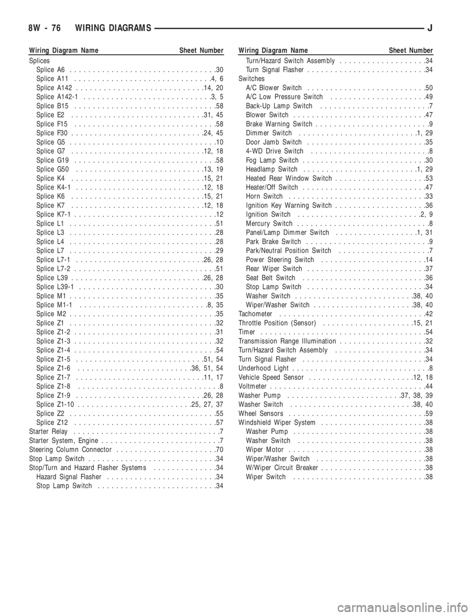
Wiring Diagram Name Sheet Number
Splices
Splice A6................................30
Splice A11..............................4,6
Splice A142............................14, 20
Splice A142-1............................3,5
Splice B15...............................58
Splice E2.............................31, 45
Splice F15...............................58
Splice F30.............................24, 45
Splice G5................................10
Splice G7.............................12, 18
Splice G19...............................58
Splice G50............................13, 19
Splice K4.............................15, 21
Splice K4-1............................12, 18
Splice K6.............................15, 21
Splice K7.............................12, 18
Splice K7-1...............................12
Splice L1................................51
Splice L3................................28
Splice L4................................28
Splice L7................................29
Splice L7-1............................26, 28
Splice L7-2...............................51
Splice L39.............................26, 28
Splice L39-1..............................30
Splice M1................................35
Splice M1-1............................8,35
Splice M2................................35
Splice Z1................................32
Splice Z1-2...............................31
Splice Z1-3...............................32
Splice Z1-4...............................54
Splice Z1-5............................51, 54
Splice Z1-6.........................36, 51, 54
Splice Z1-7............................11, 17
Splice Z1-8...............................8
Splice Z1-9............................26, 28
Splice Z1-10.........................25, 27, 37
Splice Z2................................55
Splice Z12...............................57
Starter Relay................................7
Starter System, Engine..........................7
Steering Column Connector......................70
Stop Lamp Switch............................34
Stop/Turn and Hazard Flasher Systems..............34
Hazard Signal Flasher........................34
Stop Lamp Switch..........................34Wiring Diagram Name Sheet Number
Turn/Hazard Switch Assembly...................34
Turn Signal Flasher..........................34
Switches
A/C Blower Switch..........................50
A/C Low Pressure Switch.....................49
Back-Up Lamp Switch........................7
Blower Switch.............................47
Brake Warning Switch.........................9
Dimmer Switch..........................1,29
Door Jamb Switch..........................35
4-WD Drive Switch..........................8
Fog Lamp Switch...........................30
Headlamp Switch.........................1,29
Heated Rear Window Switch....................53
Heater/Off Switch...........................47
Horn Switch..............................33
Ignition Key Warning Switch....................36
Ignition Switch...........................2,9
Mercury Switch.............................8
Panel/Lamp Dimmer Switch..................1,31
Park Brake Switch...........................9
Park/Neutral Position Switch....................7
Power Steering Switch.......................14
Rear Wiper Switch..........................37
Seat Belt Switch...........................36
Stop Lamp Switch..........................34
Washer Switch..........................38, 40
Wiper/Washer Switch......................38, 40
Tachometer................................42
Throttle Position (Sensor)....................15, 21
Timer....................................54
Transmission Range Illumination...................32
Turn/Hazard Switch Assembly....................34
Turn Signal Flasher...........................34
Underhood Light..............................8
Vehicle Speed Sensor.......................12, 18
Voltmeter..................................44
Washer Pump.........................37, 38, 39
Washer Switch...........................38, 40
Wheel Sensors..............................59
Windshield Wiper System.......................38
Washer Pump.............................38
Washer Switch............................38
Wiper Motor..............................38
Wiper/Washer Switch........................38
W/Wiper Circuit Breaker.......................38
Wiper Switch.............................38
8W - 76 WIRING DIAGRAMSJ
Page 643 of 1784
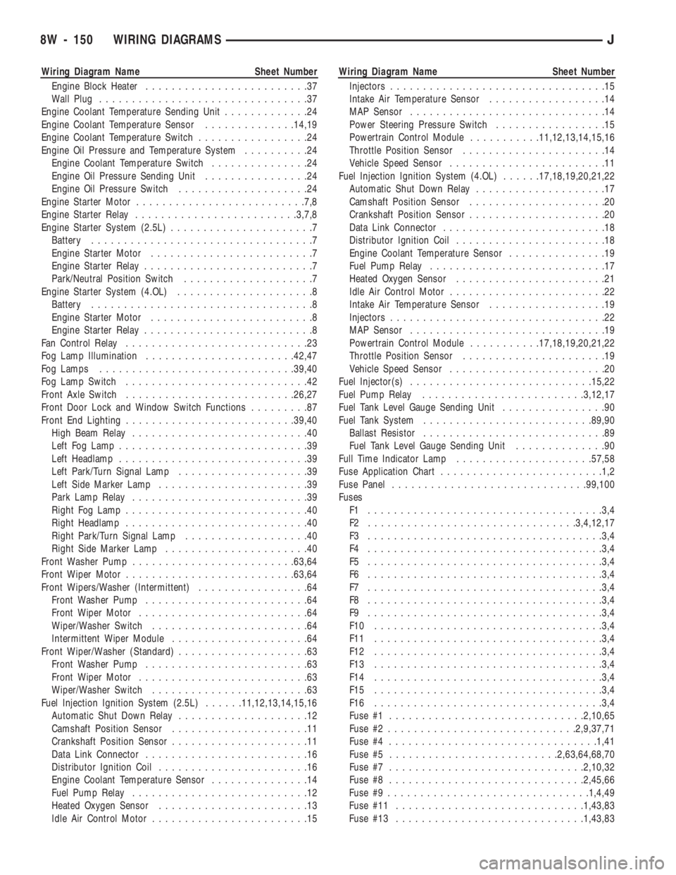
Wiring Diagram Name Sheet Number
Engine Block Heater.........................37
Wall Plug................................37
Engine Coolant Temperature Sending Unit.............24
Engine Coolant Temperature Sensor..............14,19
Engine Coolant Temperature Switch.................24
Engine Oil Pressure and Temperature System..........24
Engine Coolant Temperature Switch...............24
Engine Oil Pressure Sending Unit................24
Engine Oil Pressure Switch....................24
Engine Starter Motor..........................7,8
Engine Starter Relay.........................3,7,8
Engine Starter System (2.5L)......................7
Battery..................................7
Engine Starter Motor.........................7
Engine Starter Relay..........................7
Park/Neutral Position Switch....................7
Engine Starter System (4.OL).....................8
Battery..................................8
Engine Starter Motor.........................8
Engine Starter Relay..........................8
Fan Control Relay............................23
Fog Lamp Illumination.......................42,47
Fog Lamps..............................39,40
Fog Lamp Switch............................42
Front Axle Switch..........................26,27
Front Door Lock and Window Switch Functions.........87
Front End Lighting..........................39,40
High Beam Relay...........................40
Left Fog Lamp.............................39
Left Headlamp.............................39
Left Park/Turn Signal Lamp....................39
Left Side Marker Lamp.......................39
Park Lamp Relay...........................39
Right Fog Lamp............................40
Right Headlamp............................40
Right Park/Turn Signal Lamp...................40
Right Side Marker Lamp......................40
Front Washer Pump.........................63,64
Front Wiper Motor..........................63,64
Front Wipers/Washer (Intermittent).................64
Front Washer Pump.........................64
Front Wiper Motor..........................64
Wiper/Washer Switch........................64
Intermittent Wiper Module.....................64
Front Wiper/Washer (Standard)....................63
Front Washer Pump.........................63
Front Wiper Motor..........................63
Wiper/Washer Switch........................63
Fuel Injection Ignition System (2.5L)......11,12,13,14,15,16
Automatic Shut Down Relay....................12
Camshaft Position Sensor.....................11
Crankshaft Position Sensor.....................11
Data Link Connector.........................16
Distributor Ignition Coil.......................16
Engine Coolant Temperature Sensor...............14
Fuel Pump Relay...........................12
Heated Oxygen Sensor.......................13
Idle Air Control Motor........................15Wiring Diagram Name Sheet Number
Injectors.................................15
Intake Air Temperature Sensor..................14
MAP Sensor..............................14
Power Steering Pressure Switch.................15
Powertrain Control Module...........11,12,13,14,15,16
Throttle Position Sensor......................14
Vehicle Speed Sensor........................11
Fuel Injection Ignition System (4.OL)......17,18,19,20,21,22
Automatic Shut Down Relay....................17
Camshaft Position Sensor.....................20
Crankshaft Position Sensor.....................20
Data Link Connector.........................18
Distributor Ignition Coil.......................18
Engine Coolant Temperature Sensor...............19
Fuel Pump Relay...........................17
Heated Oxygen Sensor.......................21
Idle Air Control Motor........................22
Intake Air Temperature Sensor..................19
Injectors.................................22
MAP Sensor..............................19
Powertrain Control Module...........17,18,19,20,21,22
Throttle Position Sensor......................19
Vehicle Speed Sensor........................20
Fuel Injector(s)............................15,22
Fuel Pump Relay.........................3,12,17
Fuel Tank Level Gauge Sending Unit................90
Fuel Tank System..........................89,90
Ballast Resistor............................89
Fuel Tank Level Gauge Sending Unit..............90
Full Time Indicator Lamp.....................57,58
Fuse Application Chart.........................1,2
Fuse Panel..............................99,100
Fuses
F1 ....................................3,4
F2 ................................3,4,12,17
F3 ....................................3,4
F4 ....................................3,4
F5 ....................................3,4
F6 ....................................3,4
F7 ....................................3,4
F8 ....................................3,4
F9 ....................................3,4
F10 ...................................3,4
F11 ...................................3,4
F12 ...................................3,4
F13 ...................................3,4
F14 ...................................3,4
F15 ...................................3,4
F16 ...................................3,4
Fuse #1..............................2,10,65
Fuse #2.............................2,9,37,71
Fuse #4................................1,41
Fuse #5..........................2,63,64,68,70
Fuse #7..............................2,10,32
Fuse #8..............................2,45,66
Fuse #9...............................1,4,49
Fuse #11.............................1,43,83
Fuse #13.............................1,43,83
8W - 150 WIRING DIAGRAMSJ