Page 299 of 1784

4.0L STARTER GENERAL INFORMATION
The Mitsubishi starter motor is a light-weight unit
featuring a planetary gear drive and permanent
magnets for current induction.
The planetary gear drive is splined to both the ar-
mature shaft and overrunning clutch. Starter torque
is transmitted to the overrunning clutch pinion
through the planetary gears which provide higher ro-
tational speeds.
The starter magnetic field is produced by six per-
manent magnets. The magnets are mounted in the
starter frame and positioned according to polarity.
They are permanently attached to the frame and are
not removable.
The starter motor is activated by a solenoid
mounted on the overrunning clutch housing.
This unit is highly sensitive to hammering, shocks,
and external pressure.
CAUTION: The starter motor MUST NOT BE
CLAMPED in a vise by the starter frame. Doing so
may damage the magnets. It may be clamped by the
mounting flange ONLY.
CAUTION: Do not connect the starter motor incor-
rectly when performing tests. The magnets may be
damaged and rendered unserviceable.
²Ensure cleanliness when performing repairs.
²Metal chips are attracted by the magnets and may
not be completely removed from the starter frame.
Chips in the ring gear can lead to failure of the
starter.
4.0L STARTER MOTOR REMOVAL/INSTALLATION
(1) Disconnect negative cable from battery.
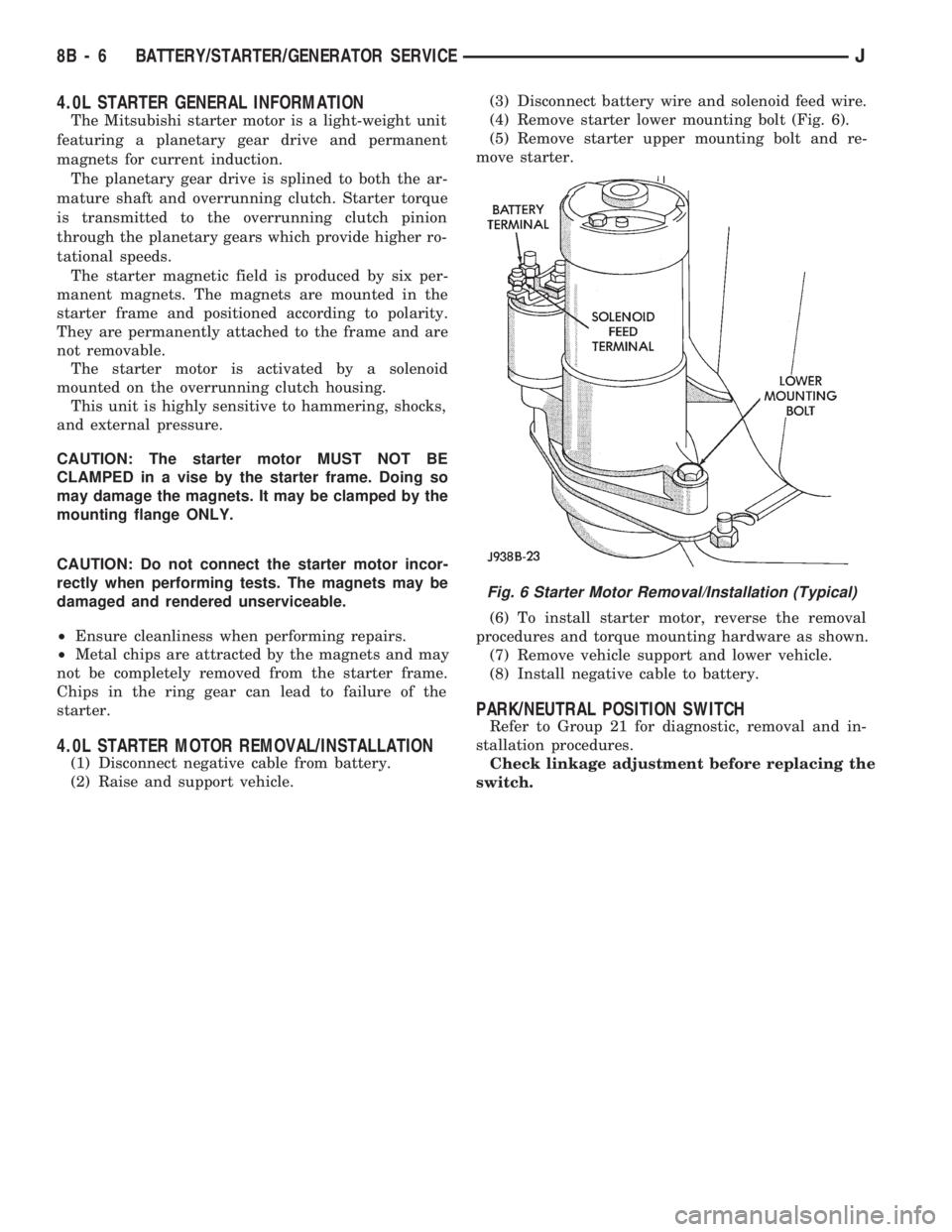
(2) Raise and support vehicle.(3) Disconnect battery wire and solenoid feed wire.
(4) Remove starter lower mounting bolt (Fig. 6).
(5) Remove starter upper mounting bolt and re-
move starter.
(6) To install starter motor, reverse the removal
procedures and torque mounting hardware as shown.
(7) Remove vehicle support and lower vehicle.
(8) Install negative cable to battery.
PARK/NEUTRAL POSITION SWITCH
Refer to Group 21 for diagnostic, removal and in-
stallation procedures.
Check linkage adjustment before replacing the
switch.
Fig. 6 Starter Motor Removal/Installation (Typical)
8B - 6 BATTERY/STARTER/GENERATOR SERVICEJ
Page 300 of 1784

GENERATOR SERVICE PROCEDURES
GENERAL
The generator is belt-driven by the engine. All en-
gines use serpentine drive. This section will cover
generator removal and installation. The generator is
not serviceable. Information covering on-vehicle test-
ing can be found in Group 8A - Battery/Starting/
Charging Systems Diagnostics.
GENERATOR REPLACEMENTÐLEFT HAND DRIVE
WARNING: FAILURE TO DISCONNECT NEGATIVE
CABLE FROM BATTERY BEFORE DISCONNECTING
RED (OUTPUT) WIRE CONNECTOR FROM GENER-
ATOR CAN RESULT IN INJURY.
ALL YJ AND XJ WITH 2.5L ENGINE
Belt tension is adjusted at the power steering pump
(or idler pulley if not equipped with power steering).
To replace generator:
(1) Disconnect negative cable from battery.
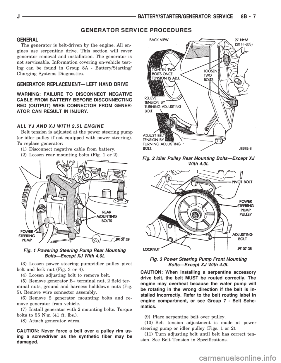
(2) Loosen rear mounting bolts (Fig. 1 or 2).
(3) Loosen power steering pump/idler pulley pivot
bolt and lock nut (Fig. 3 or 4).
(4) Loosen adjusting bolt to remove belt.
(5) Remove generator B+ terminal nut, 2 field ter-
minal nuts, ground and harness holddown nuts (Fig.
5). Remove wire connector assembly.
(6) Remove 2 generator mounting bolts and re-
move generator from vehicle.
(7) Install generator with 2 mounting bolts. Torque
bolts to 55 Nzm (41 ft. lbs.).
(8) Attach generator wires.
CAUTION: Never force a belt over a pulley rim us-
ing a screwdriver as the synthetic fiber may be
damaged.CAUTION: When installing a serpentine accessory
drive belt, the belt MUST be routed correctly. The
engine may overheat because the water pump will
be rotating in the wrong direction if the belt is in-
stalled incorrectly. Refer to the belt routing label in
engine compartment, or see Group 7 - Belt Sche-
matics.
(9) Place serpentine belt over pulley.
(10) Belt tension adjustment is made at power
steering pump or idler pulley (Figs. 1 or 2).
(11) Turn adjusting bolt until belt has correct ten-
sion. See Belt Tension in Specifications.
Fig. 1 Powering Steering Pump Rear Mounting
BoltsÐExcept XJ With 4.0L
Fig. 2 Idler Pulley Rear Mounting BoltsÐExcept XJ
With 4.0L
Fig. 3 Power Steering Pump Front Mounting
BoltsÐExcept XJ With 4.0L
JBATTERY/STARTER/GENERATOR SERVICE 8B - 7
Page 301 of 1784

(12) Tighten rear mounting bolts, pivot bolt, and
lock nut to 27 Nzm (20 ft. lbs.) torque.
(13) Connect negative cable to battery.
XJ WITH 4.0L ENGINE
Belt tension is adjusted at the power steering
pump.
To replace generator:
(1) Disconnect negative cable from battery.
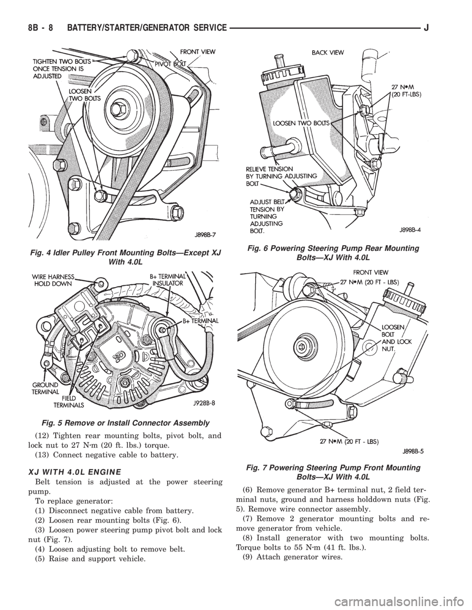
(2) Loosen rear mounting bolts (Fig. 6).
(3) Loosen power steering pump pivot bolt and lock
nut (Fig. 7).
(4) Loosen adjusting bolt to remove belt.
(5) Raise and support vehicle.(6) Remove generator B+ terminal nut, 2 field ter-
minal nuts, ground and harness holddown nuts (Fig.
5). Remove wire connector assembly.
(7) Remove 2 generator mounting bolts and re-
move generator from vehicle.
(8) Install generator with two mounting bolts.
Torque bolts to 55 Nzm (41 ft. lbs.).
(9) Attach generator wires.
Fig. 4 Idler Pulley Front Mounting BoltsÐExcept XJ
With 4.0L
Fig. 5 Remove or Install Connector Assembly
Fig. 6 Powering Steering Pump Rear Mounting
BoltsÐXJ With 4.0L
Fig. 7 Powering Steering Pump Front Mounting
BoltsÐXJ With 4.0L
8B - 8 BATTERY/STARTER/GENERATOR SERVICEJ
Page 302 of 1784

CAUTION: Never force a belt over a pulley rim us-
ing a screwdriver as the synthetic fiber may be
damaged.
CAUTION: When installing a serpentine accessory
drive belt, the belt MUST be routed correctly. The
engine may overheat because the water pump will
be rotating in the wrong direction if the belt is in-
stalled incorrectly. Refer to the belt routing label in
engine compartment, or see Group 7 - Belt Sche-
matics.
(10) Place serpentine belt over pulley.
(11) Belt tension adjustment is made at power
steering pump (Fig. 6).
(12) Turn adjusting bolt until belt has correct ten-
sion. See Belt Tension in Specifications.
(13) Tighten rear mounting bolts, pivot bolt, and
lock nut to 27 Nzm (20 ft. lbs.) torque.
(14) Remove support and lower vehicle.
(15) Connect negative cable to battery.
GENERATOR REPLACEMENTÐRIGHT HAND DRIVE
The generator used on the right hand drive is the
same as used on left hand drive. However, the
mounting and accessory drive belt installation are
different.
WARNING: FAILURE TO DISCONNECT NEGATIVE
CABLE FROM BATTERY BEFORE DISCONNECTING
RED (OUTPUT) WIRE CONNECTOR FROM GENER-
ATOR CAN RESULT IN INJURY.
(1) Remove negative cable from battery.
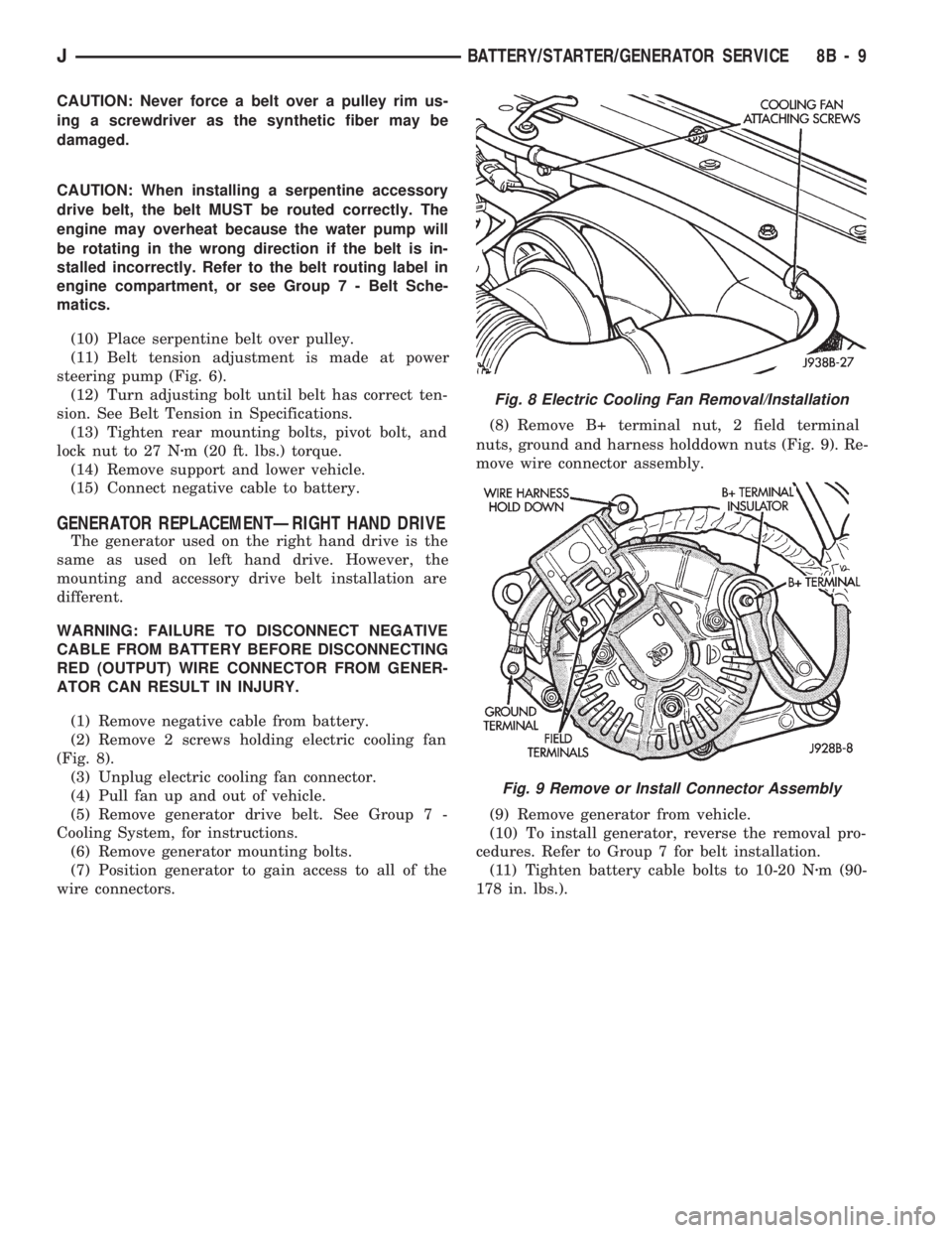
(2) Remove 2 screws holding electric cooling fan
(Fig. 8).
(3) Unplug electric cooling fan connector.
(4) Pull fan up and out of vehicle.
(5) Remove generator drive belt. See Group 7 -
Cooling System, for instructions.
(6) Remove generator mounting bolts.
(7) Position generator to gain access to all of the
wire connectors.(8) Remove B+ terminal nut, 2 field terminal
nuts, ground and harness holddown nuts (Fig. 9). Re-
move wire connector assembly.
(9) Remove generator from vehicle.
(10) To install generator, reverse the removal pro-
cedures. Refer to Group 7 for belt installation.
(11) Tighten battery cable bolts to 10-20 Nzm (90-
178 in. lbs.).
Fig. 8 Electric Cooling Fan Removal/Installation
Fig. 9 Remove or Install Connector Assembly
JBATTERY/STARTER/GENERATOR SERVICE 8B - 9
Page 303 of 1784
SPECIFICATIONS
BATTERY CLASSIFICATIONS AND
RATINGSÐLEFT HAND DRIVE
BATTERY CLASSIFICATIONS AND
RATINGSÐRIGHT HAND DRIVE
BATTERY TORQUE SPECIFICATIONS
BELT TENSION
8B - 10 BATTERY/STARTER/GENERATOR SERVICEJ
Page 304 of 1784
4.0L ENGINES 2.5L ENGINES
4.0L STARTER MOTOR AND SOLENOID
TESTING SPECIFICATIONS
STARTING SYSTEM COLD CRANKING
SPECIFICATIONS
STARTER MOTOR TORQUE SPECIFICATIONS
2.5L STARTER MOTOR SPECIFICATIONS
STARTING SYSTEM COLD CRANKING
SPECIFICATIONS
STARTER MOTOR TORQUE SPECIFICATIONS
JBATTERY/STARTER/GENERATOR SERVICE 8B - 11
Page 305 of 1784
GENERATOR SPECIFICATIONS
TORQUE SPECIFICATIONS
OUTPUT VOLTAGE SPECIFICATIONS
8B - 12 BATTERY/STARTER/GENERATOR SERVICEJ
Page 321 of 1784

DIAGNOSTICS/SERVICE PROCEDURES
INDEX
page page
Automatic Shut Down (ASD) Relay............ 8
Camshaft Position Sensor Test............... 8
Crankshaft Position Sensor Test.............. 9
Distributor Cap........................... 9
Distributor Rotor......................... 10
DRB Scan Tool.......................... 10
Engine Coolant Temperature Sensor Test...... 12
General Information........................ 8
Ignition Coil............................. 11
Ignition Secondary Circuit Diagnosis.......... 12Ignition Timing........................... 14
Intake Manifold Air Temperature Sensor Test . . . 14
Manifold Absolute Pressure (MAP) Sensor Test . 14
On-Board Diagnostics (OBD)................ 19
Oxygen Sensor Tests..................... 19
Powertrain Control Module (PCM)............ 15
Spark Plug Secondary Cables............... 17
Spark Plugs............................ 16
Throttle Position Sensor Test............... 18
GENERAL INFORMATION
This section of the group, Diagnostics/Service Pro-
cedures, will discuss basic ignition system diagnos-
tics and service adjustments.
For system operation and component identification,
refer to the Component Identification/System Opera-
tion section of this group.
For removal or installation of ignition system com-
ponents, refer to the Component Removal/Installa-
tion section of this group.
For other useful information, refer to On-Board Di-
agnostics in the General Diagnosis sections of Group
14, Fuel System in this manual.
For operation of the DRB Scan Tool, refer to the
appropriate Powertrain Diagnostic Procedures ser-
vice manual.
AUTOMATIC SHUT DOWN (ASD) RELAY
Refer to RelaysÐOperation/Testing in the Group
14, Fuel System section of this service manual.
CAMSHAFT POSITION SENSOR TEST
The camshaft position sensor is located in the dis-
tributor on all engines.
To perform a complete test of this sensor and its
circuitry, refer to the DRB scan tool. Also refer to the
appropriate Powertrain Diagnostics Procedures man-
ual. To test the sensor only, refer to the following:
2.5L OR 4.0L ENGINE
For this test, an analog voltmeter is needed.Do
not remove the distributor connector from the dis-
tributor. Using small paper clips, insert them into
the backside of the distributor wire harness connec-
tor to make contact with the terminals. Be sure that
the connector is not damaged when inserting the pa-
per clips. Attach voltmeter leads to these paper clips.
(1) Connect the positive (+) voltmeter lead into
the sensor output wire. This is at done the distribu-
tor wire harness connector. For wire identification,
refer to Group 8W, Wiring Diagrams.(2) Connect the negative (-) voltmeter lead into the
ground wire. For wire identification, refer to Group
8W, Wiring Diagrams.
(3) Set the voltmeter to the 15 Volt DC scale.
(4) Remove distributor cap. Rotate (crank) engine
with starter until pulse ring (Fig. 1) enters the mag-
netic pickup on camshaft position sensor. Distributor
rotor should be pointed in 9 o'clock position. The
movable pulse ring should now be within the sensor
pickup.
(5) Turn ignition key to ON position. Voltmeter
should read approximately 5.0 volts.
(6) If voltage is not present, check the voltmeter
leads for a good connection.
(7) If voltage is still not present, check for voltage
at the supply wire. For wire identification, refer to
Group 8W, Wiring Diagrams.
Fig. 1 Pulse Ring/Rotor PositionÐTypical
8D - 8 IGNITION SYSTEMSJ