1994 JEEP CHEROKEE Starter
[x] Cancel search: StarterPage 999 of 1784
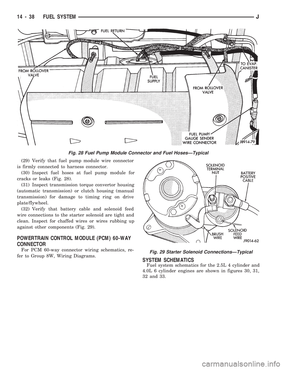
(29) Verify that fuel pump module wire connector
is firmly connected to harness connector.
(30) Inspect fuel hoses at fuel pump module for
cracks or leaks (Fig. 28).
(31) Inspect transmission torque convertor housing
(automatic transmission) or clutch housing (manual
transmission) for damage to timing ring on drive
plate/flywheel.
(32) Verify that battery cable and solenoid feed
wire connections to the starter solenoid are tight and
clean. Inspect for chaffed wires or wires rubbing up
against other components (Fig. 29).
POWERTRAIN CONTROL MODULE (PCM) 60-WAY
CONNECTOR
For PCM 60-way connector wiring schematics, re-
fer to Group 8W, Wiring Diagrams.
SYSTEM SCHEMATICS
Fuel system schematics for the 2.5L 4 cylinder and
4.0L 6 cylinder engines are shown in figures 30, 31,
32 and 33.
Fig. 28 Fuel Pump Module Connector and Fuel HosesÐTypical
Fig. 29 Starter Solenoid ConnectionsÐTypical
14 - 38 FUEL SYSTEMJ
Page 1009 of 1784
87 and 30. Continuity should not be present between
terminals number 87A and 30.
(8) Disconnect jumper wires from relay and 12
Volt power source.
If continuity or resistance tests did not pass, re-
place relay. If tests passed, refer to Group 8W, Wir-
ing Diagrams for additional circuit information. Also
refer to the appropriate Powertrain Diagnostic Proce-
dures manual for operation of the DRB scan tool.
STARTER MOTOR RELAY TEST
Refer to Group 8A, Battery/Starting/Charging/Sys-
tem Diagnostics, for starter motor relay testing.
INJECTOR TEST
Disconnect the injector wire connector from the in-
jector. Place an ohmmeter on the injector terminals.
Resistance reading should be approximately 14.5
ohms61.2 ohms at 20ÉC (68ÉF). Proceed to following
Injector Diagnosis chart.
FUEL SYSTEM PRESSURE TEST
Refer to the Fuel Delivery System section of this
group. See Fuel System Pressure Test.
ON-BOARD DIAGNOSTICS (OBD)
The Powertrain Control Module (PCM) has been
programmed to monitor many different circuits of the
fuel injection system. If a problem is sensed in a
monitored circuit often enough to indicate an actual
problem, a Diagnostic Trouble Code (DTC) is stored.
The DTC will be stored in the PCM memory for
eventual display to the service technician. If the
problem is repaired or ceases to exist, the PCM can-
cels the DTC after 51 engine starts.
Certain criteria must be met for a diagnostic trou-
ble code (DTC) to be entered into PCM memory. The
criteria may be a specific range of engine rpm, en-
gine temperature and/or input voltage to the PCM.
It is possible that a DTC for a monitored circuit
may not be entered into memory even though a mal-
function has occurred. This may happen because one
of the DTC criteria for the circuit has not been met.
Example: assume that one of the criteria for the
MAP sensor circuit is that the engine must be oper-
ating between 750 and 2000 rpm to be monitored for
a DTC. If the MAP sensor output circuit shorts to
ground when the engine rpm is above 2400 rpm, a 0
volt input will be seen by the PCM. A DTC will not
be entered into memory because the condition does
not occur within the specified rpm range.
A DTC indicates that the powertrain control mod-
ule (PCM) has recognized an abnormal signal in a
circuit or the system. A DTC may indicate the result
of a failure, but never identify the failed component
directly.There are several operating conditions that the
PCM does not monitor and set a DTC for. Refer to
the following Monitored Circuits and Non-Monitored
Circuits in this section.
MONITORED CIRCUITS
The powertrain control module (PCM) can detect
certain problems in the fuel injection system.
Open or Shorted Circuit- The PCM can deter-
mine if sensor output (which is the input to PCM) is
within proper range. It also determines if the circuit
is open or shorted.
Output Device Current Flow- The PCM senses
whether the output devices are hooked up.
If there is a problem with the circuit, the PCM
senses whether the circuit is open, shorted to ground
(-), or shorted to (+) voltage.
Oxygen Sensor- The PCM can determine if the
oxygen sensor is switching between rich and lean.
This is, once the system has entered Closed Loop. Re-
fer to Open Loop/Closed Loop Modes Of Operation in
the Component Description/System Operation section
for an explanation of Closed (or Open) Loop opera-
tion.
NON-MONITORED CIRCUITS
The PCM does not monitor the following circuits,
systems or conditions that could have malfunctions
that result in driveability problems. A Diagnostic
Trouble Code (DTC) may not be displayed for these
conditions.
Fuel Pressure: Fuel pressure is controlled by the
vacuum assisted fuel pressure regulator. The PCM
cannot detect a clogged fuel pump inlet filter, clogged
in-line fuel filter, or a pinched fuel supply or return
line. However, these could result in a rich or lean
condition causing an oxygen sensor DTC to be stored
in the PCM.
Secondary Ignition Circuit: The PCM cannot
detect an inoperative ignition coil, fouled or worn
spark plugs, ignition cross firing, or open circuited
spark plug cables.
Engine Timing: The PCM cannot detect an incor-
rectly indexed timing chain, camshaft sprocket or
crankshaft sprocket. The PCM also cannot detect an
incorrectly indexed distributor. However, these could
result in a rich or lean condition causing an oxygen
sensor DTC to be stored in the PCM.
Cylinder Compression: The PCM cannot detect
uneven, low, or high engine cylinder compression.
Exhaust System: The PCM cannot detect a
plugged, restricted or leaking exhaust system.
Fuel Injector Malfunctions: The PCM cannot de-
termine if the fuel injector is clogged, or the wrong
injector is installed. However, these could result in a
rich or lean condition causing an oxygen sensor DTC
to be stored in the PCM.
14 - 48 FUEL SYSTEMJ
Page 1214 of 1784
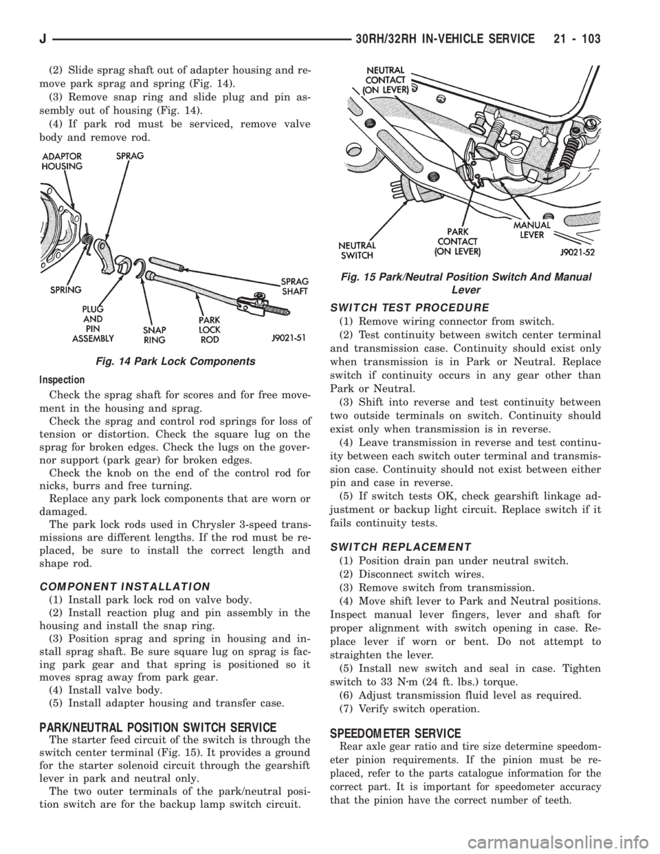
(2) Slide sprag shaft out of adapter housing and re-
move park sprag and spring (Fig. 14).
(3) Remove snap ring and slide plug and pin as-
sembly out of housing (Fig. 14).
(4) If park rod must be serviced, remove valve
body and remove rod.
Inspection
Check the sprag shaft for scores and for free move-
ment in the housing and sprag.
Check the sprag and control rod springs for loss of
tension or distortion. Check the square lug on the
sprag for broken edges. Check the lugs on the gover-
nor support (park gear) for broken edges.
Check the knob on the end of the control rod for
nicks, burrs and free turning.
Replace any park lock components that are worn or
damaged.
The park lock rods used in Chrysler 3-speed trans-
missions are different lengths. If the rod must be re-
placed, be sure to install the correct length and
shape rod.
COMPONENT INSTALLATION
(1) Install park lock rod on valve body.
(2) Install reaction plug and pin assembly in the
housing and install the snap ring.
(3) Position sprag and spring in housing and in-
stall sprag shaft. Be sure square lug on sprag is fac-
ing park gear and that spring is positioned so it
moves sprag away from park gear.
(4) Install valve body.
(5) Install adapter housing and transfer case.
PARK/NEUTRAL POSITION SWITCH SERVICE
The starter feed circuit of the switch is through the
switch center terminal (Fig. 15). It provides a ground
for the starter solenoid circuit through the gearshift
lever in park and neutral only.
The two outer terminals of the park/neutral posi-
tion switch are for the backup lamp switch circuit.
SWITCH TEST PROCEDURE
(1) Remove wiring connector from switch.
(2) Test continuity between switch center terminal
and transmission case. Continuity should exist only
when transmission is in Park or Neutral. Replace
switch if continuity occurs in any gear other than
Park or Neutral.
(3) Shift into reverse and test continuity between
two outside terminals on switch. Continuity should
exist only when transmission is in reverse.
(4) Leave transmission in reverse and test continu-
ity between each switch outer terminal and transmis-
sion case. Continuity should not exist between either
pin and case in reverse.
(5) If switch tests OK, check gearshift linkage ad-
justment or backup light circuit. Replace switch if it
fails continuity tests.
SWITCH REPLACEMENT
(1) Position drain pan under neutral switch.
(2) Disconnect switch wires.
(3) Remove switch from transmission.
(4) Move shift lever to Park and Neutral positions.
Inspect manual lever fingers, lever and shaft for
proper alignment with switch opening in case. Re-
place lever if worn or bent. Do not attempt to
straighten the lever.
(5) Install new switch and seal in case. Tighten
switch to 33 Nzm (24 ft. lbs.) torque.
(6) Adjust transmission fluid level as required.
(7) Verify switch operation.
SPEEDOMETER SERVICE
Rear axle gear ratio and tire size determine speedom-
eter pinion requirements. If the pinion must be re-
placed, refer to the parts catalogue information for the
correct part. It is important for speedometer accuracy
that the pinion have the correct number of teeth.
Fig. 14 Park Lock Components
Fig. 15 Park/Neutral Position Switch And Manual
Lever
J30RH/32RH IN-VEHICLE SERVICE 21 - 103
Page 1219 of 1784
30RH/32RH TRANSMISSION REMOVAL AND INSTALLATION
INDEX
page page
ConverterÐPump SealÐDrive Plate Service . . . 109
Transmission and Converter Installation....... 109Transmission and Converter Removal........ 108
TRANSMISSION AND CONVERTER REMOVAL
(1) Remove fan shroud attaching bolts.
(2) Disconnect transmission fill tube at upper
bracket.
(3) Raise vehicle.
(4) Remove inspection cover from converter hous-
ing and remove skid plate for access, if necessary.
(5) Remove transmission fill tube and fill tube
O-ring.
(6) Remove starter motor.
(7) Mark propeller shafts and axle yokes for align-
ment reference.
(8) Disconnect propeller shafts at yokes. Secure
shafts to frame rails with wire.
(9) Disconnect exhaust pipes at exhaust manifolds,
if necessary.
(10) Drain transfer case lubricant.
(11) Disconnect vehicle speed sensor wires.
(12) Disconnect transfer case shift linkage.
(13) Disconnect gearshift linkage and throttle ca-
ble at transmission levers.
(14) Disconnect park/neutral position switch wires.
(15) Disconnect and remove crankshaft position
sensor. Retain sensor bolt for reinstallation.
CAUTION: The crankshaft position sensor can be
damaged during transmission removal (or installa-
tion) if the sensor is still bolted to the engine block.
To avoid damage, remove the sensor before remov-
ing the transmission.
(16) Remove converter housing access cover and
mark drive plate and converter for alignment refer-
ence.
(17) Remove bolts attaching converter to drive
plate.
(18) Support engine with support stand.
(19) Support transmission-transfer case assembly
with transmission jack. Secure transmission to jack
with safety chain.
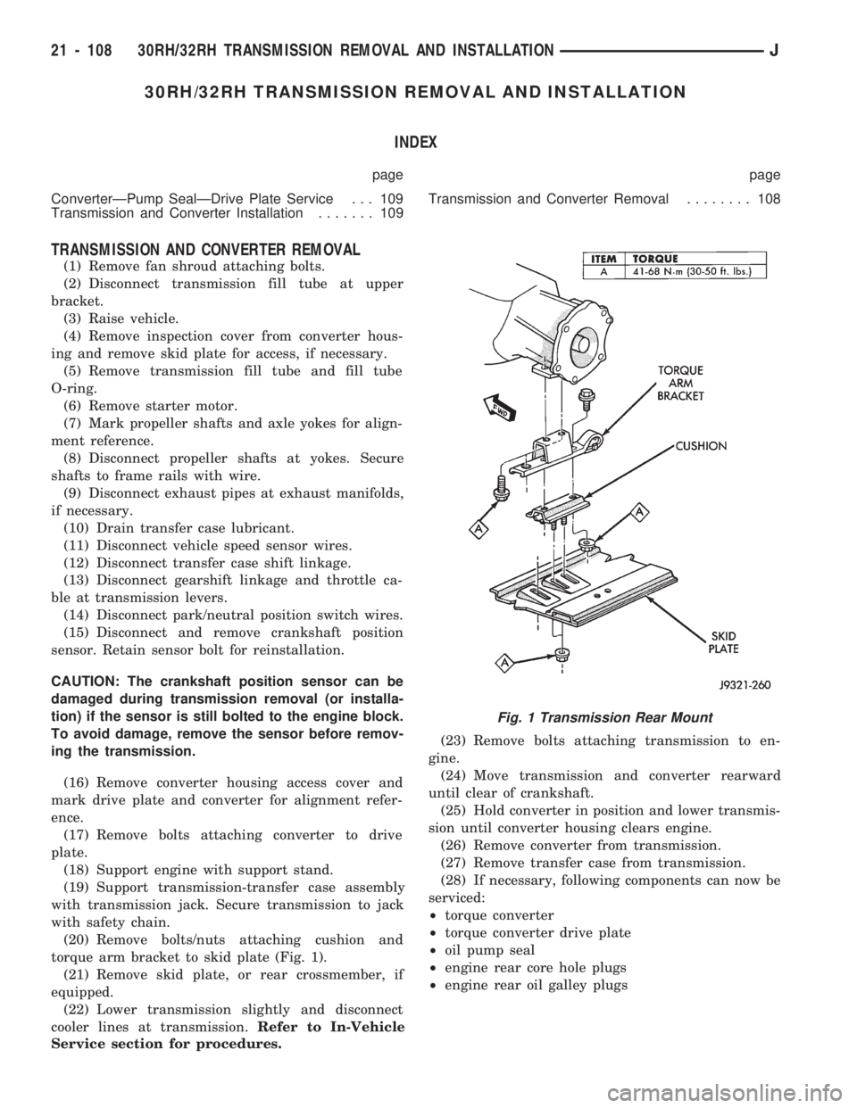
(20) Remove bolts/nuts attaching cushion and
torque arm bracket to skid plate (Fig. 1).
(21) Remove skid plate, or rear crossmember, if
equipped.
(22) Lower transmission slightly and disconnect
cooler lines at transmission.Refer to In-Vehicle
Service section for procedures.(23) Remove bolts attaching transmission to en-
gine.
(24) Move transmission and converter rearward
until clear of crankshaft.
(25) Hold converter in position and lower transmis-
sion until converter housing clears engine.
(26) Remove converter from transmission.
(27) Remove transfer case from transmission.
(28) If necessary, following components can now be
serviced:
²torque converter
²torque converter drive plate
²oil pump seal
²engine rear core hole plugs
²engine rear oil galley plugs
Fig. 1 Transmission Rear Mount
21 - 108 30RH/32RH TRANSMISSION REMOVAL AND INSTALLATIONJ
Page 1222 of 1784
(b) Align and install new spacer on sensor
pickup face. Spacer has adhesive backing so it will
adhere to sensor face.
(c) Insert sensor into housing until it just
touches ring gear teeth. Then install and tighten
sensor attaching bolt. Correct clearance is estab-
lished when spacer is peeled off by ring gear dur-
ing engine startup.
(10) Install transmission fill tube and O-ring (Fig.
6).
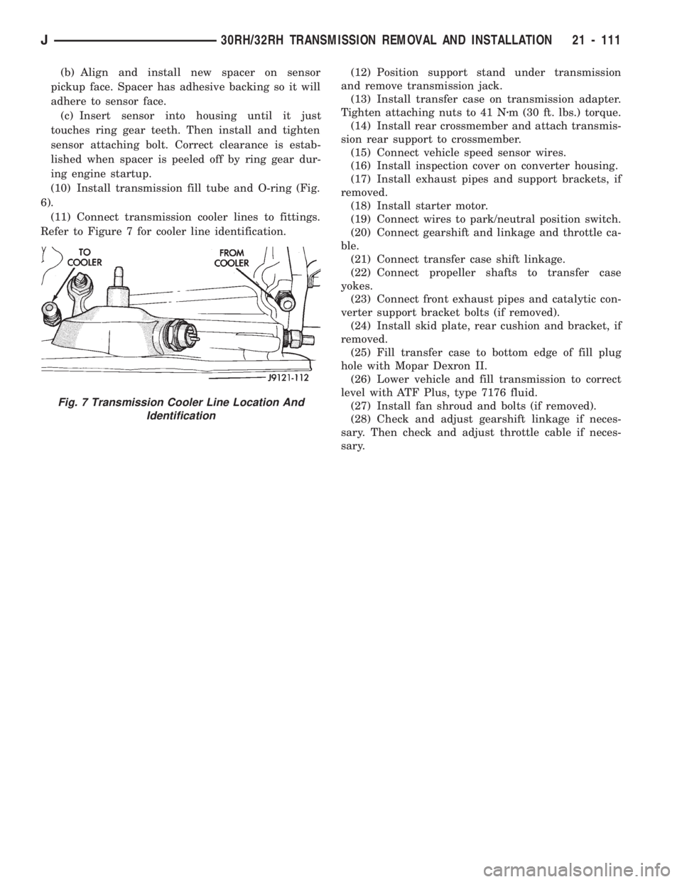
(11) Connect transmission cooler lines to fittings.
Refer to Figure 7 for cooler line identification.(12) Position support stand under transmission
and remove transmission jack.
(13) Install transfer case on transmission adapter.
Tighten attaching nuts to 41 Nzm (30 ft. lbs.) torque.
(14) Install rear crossmember and attach transmis-
sion rear support to crossmember.
(15) Connect vehicle speed sensor wires.
(16) Install inspection cover on converter housing.
(17) Install exhaust pipes and support brackets, if
removed.
(18) Install starter motor.
(19) Connect wires to park/neutral position switch.
(20) Connect gearshift and linkage and throttle ca-
ble.
(21) Connect transfer case shift linkage.
(22) Connect propeller shafts to transfer case
yokes.
(23) Connect front exhaust pipes and catalytic con-
verter support bracket bolts (if removed).
(24) Install skid plate, rear cushion and bracket, if
removed.
(25) Fill transfer case to bottom edge of fill plug
hole with Mopar Dexron II.
(26) Lower vehicle and fill transmission to correct
level with ATF Plus, type 7176 fluid.
(27) Install fan shroud and bolts (if removed).
(28) Check and adjust gearshift linkage if neces-
sary. Then check and adjust throttle cable if neces-
sary.
Fig. 7 Transmission Cooler Line Location And
Identification
J30RH/32RH TRANSMISSION REMOVAL AND INSTALLATION 21 - 111
Page 1300 of 1784
AW-4 TRANSMISSION REMOVAL AND INSTALLATION
INDEX
page page
Oil Pump Seal Replacement............... 189
Torque Converter Stator Clutch Inspection..... 189Transmission and Torque Converter Installation . 190
Transmission and Torque Converter Removal . . 189
TRANSMISSION AND TORQUE CONVERTER
REMOVAL
(1) Raise vehicle.
(2) Drain transmission fluid and reinstall oil pan
drain plug.
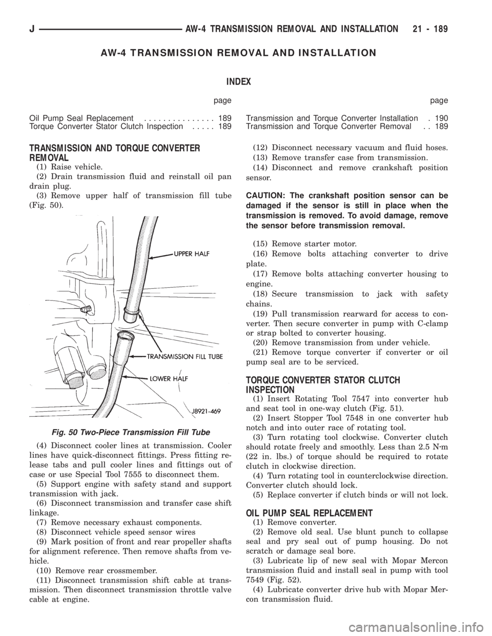
(3) Remove upper half of transmission fill tube
(Fig. 50).
(4) Disconnect cooler lines at transmission. Cooler
lines have quick-disconnect fittings. Press fitting re-
lease tabs and pull cooler lines and fittings out of
case or use Special Tool 7555 to disconnect them.
(5) Support engine with safety stand and support
transmission with jack.
(6) Disconnect transmission and transfer case shift
linkage.
(7) Remove necessary exhaust components.
(8) Disconnect vehicle speed sensor wires
(9) Mark position of front and rear propeller shafts
for alignment reference. Then remove shafts from ve-
hicle.
(10) Remove rear crossmember.
(11) Disconnect transmission shift cable at trans-
mission. Then disconnect transmission throttle valve
cable at engine.(12) Disconnect necessary vacuum and fluid hoses.
(13) Remove transfer case from transmission.
(14) Disconnect and remove crankshaft position
sensor.
CAUTION: The crankshaft position sensor can be
damaged if the sensor is still in place when the
transmission is removed. To avoid damage, remove
the sensor before transmission removal.
(15) Remove starter motor.
(16) Remove bolts attaching converter to drive
plate.
(17) Remove bolts attaching converter housing to
engine.
(18) Secure transmission to jack with safety
chains.
(19) Pull transmission rearward for access to con-
verter. Then secure converter in pump with C-clamp
or strap bolted to converter housing.
(20) Remove transmission from under vehicle.
(21) Remove torque converter if converter or oil
pump seal are to be serviced.
TORQUE CONVERTER STATOR CLUTCH
INSPECTION
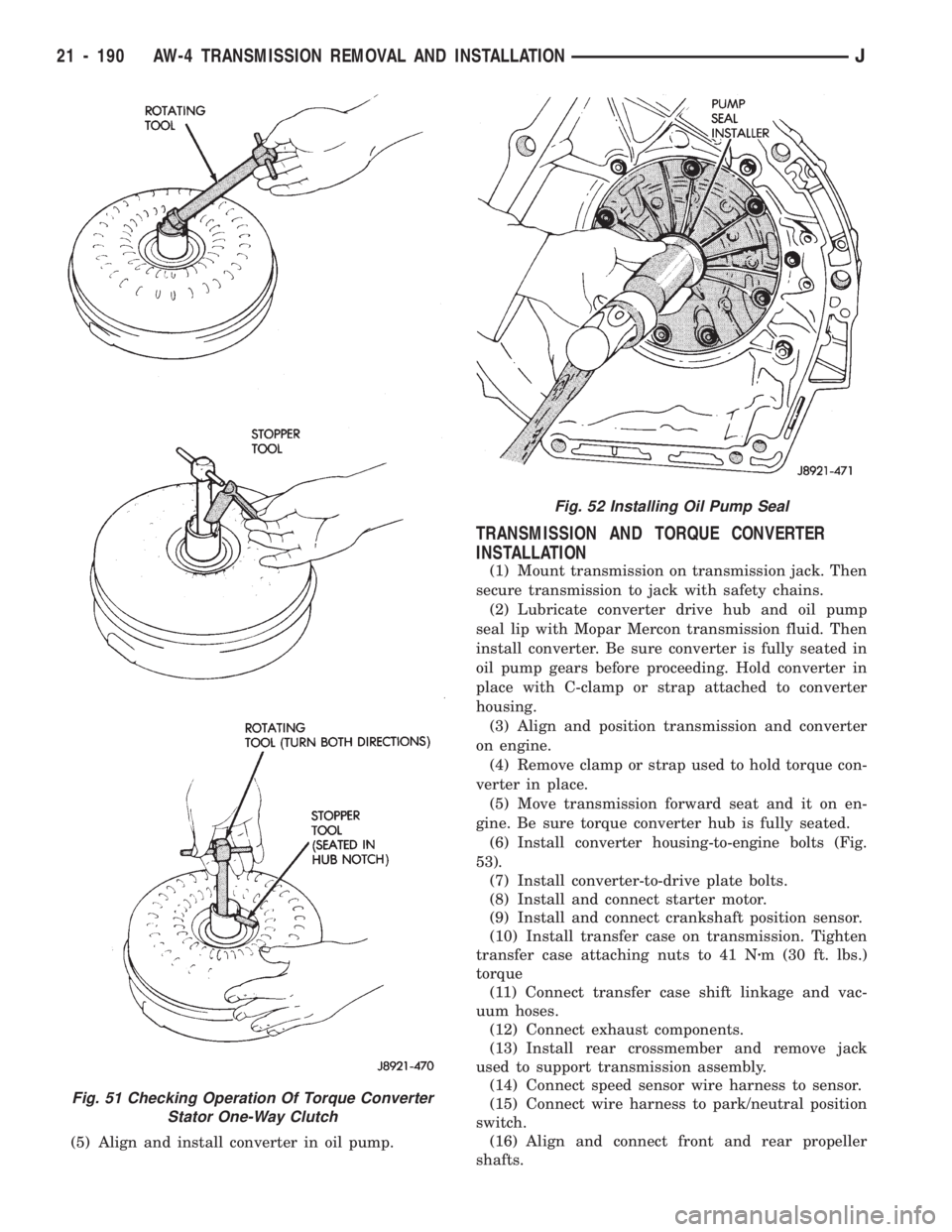
(1) Insert Rotating Tool 7547 into converter hub
and seat tool in one-way clutch (Fig. 51).
(2) Insert Stopper Tool 7548 in one converter hub
notch and into outer race of rotating tool.
(3) Turn rotating tool clockwise. Converter clutch
should rotate freely and smoothly. Less than 2.5 Nzm
(22 in. lbs.) of torque should be required to rotate
clutch in clockwise direction.
(4) Turn rotating tool in counterclockwise direction.
Converter clutch should lock.
(5)
Replace converter if clutch binds or will not lock.
OIL PUMP SEAL REPLACEMENT
(1) Remove converter.
(2) Remove old seal. Use blunt punch to collapse
seal and pry seal out of pump housing. Do not
scratch or damage seal bore.
(3) Lubricate lip of new seal with Mopar Mercon
transmission fluid and install seal in pump with tool
7549 (Fig. 52).
(4) Lubricate converter drive hub with Mopar Mer-
con transmission fluid.
Fig. 50 Two-Piece Transmission Fill Tube
JAW-4 TRANSMISSION REMOVAL AND INSTALLATION 21 - 189
Page 1301 of 1784
(5) Align and install converter in oil pump.
TRANSMISSION AND TORQUE CONVERTER
INSTALLATION
(1) Mount transmission on transmission jack. Then
secure transmission to jack with safety chains.
(2) Lubricate converter drive hub and oil pump
seal lip with Mopar Mercon transmission fluid. Then
install converter. Be sure converter is fully seated in
oil pump gears before proceeding. Hold converter in
place with C-clamp or strap attached to converter
housing.
(3) Align and position transmission and converter
on engine.
(4) Remove clamp or strap used to hold torque con-
verter in place.
(5) Move transmission forward seat and it on en-
gine. Be sure torque converter hub is fully seated.
(6)
Install converter housing-to-engine bolts (Fig.
53).
(7) Install converter-to-drive plate bolts.
(8) Install and connect starter motor.
(9) Install and connect crankshaft position sensor.
(10) Install transfer case on transmission. Tighten
transfer case attaching nuts to 41 Nzm (30 ft. lbs.)
torque
(11) Connect transfer case shift linkage and vac-
uum hoses.
(12) Connect exhaust components.
(13) Install rear crossmember and remove jack
used to support transmission assembly.
(14) Connect speed sensor wire harness to sensor.
(15) Connect wire harness to park/neutral position
switch.
(16) Align and connect front and rear propeller
shafts.
Fig. 51 Checking Operation Of Torque Converter
Stator One-Way Clutch
Fig. 52 Installing Oil Pump Seal
21 - 190 AW-4 TRANSMISSION REMOVAL AND INSTALLATIONJ
Page 1748 of 1784
CARPET/FLOOR MATS.................23-198
CARPET/MATÐXJ VEHICLES, FRONT.....23-129
CARPET/MATÐXJ VEHICLES, REAR......23-130
CARPETS AND FLOOR MATS............23-129
CARRIER, EXTERNAL SPARE/WHEEL
TIRE..............................23-172
CASE ASSEMBLY, TRANSFER......21-282,21-306
CASE CLEANING AND INSPECTION,
TRANSMISSION.....................21-118
CASE COVER OIL SEAL REPLACEMENT,
TIMING.........................9-26,9-67
CASE COVER, TIMING...............9-27,9-67
CASE DISASSEMBLY AND OVERHAUL,
TRANSFER...................21-277,21-297
CASE FILL LEVEL, TRANSFER...........21-294
CASE IDENTIFICATION, ENGINE AND
TRANSMISSION/TRANSFER..........INTRO.-3
CASE IDENTIFICATION, TRANSFER . 21-273,21-293
CASE INSTALLATION, TRANSFER . . . 21-276,21-296
CASE, LEGEND FOR NP231 TRANSFER....21-292
CASE, LEGEND FOR NP242 TRANSFER....21-319
CASE LUBRICANT, TRANSFER.....21-273,21-294
CASE, NP231 TRANSFER.........21-272,21-291
CASE, NP242 TRANSFER...............21-293
CASE OVERHAUL, FIRST-REVERSE
BRAKE PISTON AND TRANSMISSION....21-237
CASE REMOVAL, TRANSFER......21-276,21-296
CASE SPECIFICATIONS, TRANSMISSION/
TRANSFER.........................21-320
CASE, TRANSFER.......................0-25
CATALYTIC CONVERTER..............11-1,11-5
CATALYTIC CONVERTER/MUFFLER/
TAILPIPE SUPPORT BRACKETS.........23-85
CAUSES, CLUTCH PROBLEM...............6-3
CENTER HIGH MOUNTED STOP LAMP
(CHMSL)ÐXJ.......................8L-10
CENTER HIGH MOUNTED STOP LAMP
(CHMSL)ÐYJ.......................8L-11
CERTIFICATION LABEL, VEHICLE SAFETY . INTRO.-1
CHAIN AND SPROCKETS, TIMING......9-28,9-68
CHANGE AND FILTER REPLACEMENT,
ENGINE OIL..........................0-15
CHANGE, LUBRICANT; FRONT
SUSPENSION AND AXLE................2-22
CHANGE, LUBRICANT; REAR SUSPENSION
AND AXLES......................3-13,3-30
CHARGE RATE.........................8A-6
CHARGE, SYSTEM......................24-5
CHARGING, BATTERY....................8A-5
CHARGING TIME TABLE, BATTERY.........8A-5
CHASSIS AND BODY COMPONENTS........0-30
CHASSIS COMPONENT AND WHEEL
BEARING LUBRICANTS.................0-30
CHECK BALL DIMENSIONS, AW-4 VALVE
BODY.............................21-328
CHECK ENGINE LAMP FOR DIAGNOSTIC
TROUBLE CODES, INDICATOR..........8A-19
CHECK ENGINE, MALFUNCTION
INDICATOR LAMP; INSTRUMENT PANEL
AND GAUGESÐXJ................8E-2,8E-4
CHECK ENGINE, MALFUNCTION
INDICATOR LAMP; INSTRUMENT PANEL
AND GAUGESÐYJ...................8E-16
CHECK, PRELIMINARY BRAKE..............5-7
CHECK (ROAD TEST), OPERATIONAL.......8H-7
CHECK VALVE REPLACEMENT............19-33
CHECK VALVE TEST, POWER BOOSTER......5-11
CHECK WITH BATTERY INDICATOR
(BASE CLUSTER ONLY), OPERATIONAL . . . 8A-14
CHECK WITH VOLTMETER, OPERATIONAL . . . 8A-15
CHECKING FLUID LEVEL AND
CONDITION...................21-96,21-173
CHECKING FOR DIAGNOSTIC TROUBLE
CODE...............................8H-5
CHECKS FIRST, SYMPTOM AND ACTIONÐ
SEE PRELIMINARY.....................7-6
CHECKS, PRELIMINARY...................7-5
CHIP PROTECTION, STONE.............23-201
CHMSLÐXJ, CENTER HIGH MOUNTED
STOP LAMP.........................8L-10
CHMSLÐYJ, CENTER HIGH MOUNTED
STOP LAMP
.........................8L-11
CIRCUIT DIAGNOSIS, IGNITION
SECONDARY
........................8D-12
CIRCUIT IDENTIFICATION
................8W-2
CIRCUIT, PRINTED
.....................8E-22CIRCUIT REMOVAL, PRINTED............8E-24
CIRCUIT REPLACEMENT, PRINTED........8E-19
CIRCUIT REPLACEMENTÐINSTRUMENT
CLUSTER REMOVED, PRINTED...........8E-6
CIRCUIT SENSEÐPCM INPUT, IGNITION....14-21
CIRCUIT TESTS - (VOLTAGE DROP
METHOD), STARTER FEED..............8A-9
CIRCUIT TESTS, STARTER CONTROL......8A-11
CIRCUIT VOLTAGE, BATTERY OPEN.........8A-4
CIRCUIT VOLTAGE TEST, BATTERY OPEN....8A-3
CIRCUITS, ABS SYSTEM WIRING AND
ELECTRICAL..........................5-4
CLAMPS, FUEL TUBES/LINES/HOSES . . 14-9,14-56
CLASSIFICATION OF LUBRICANTS...........0-2
CLASSIFICATIONS AND RATINGS,
BATTERY............................8A-8
CLASSIFICATIONS AND RATINGSÐ
LEFT HAND DRIVE, BATTERY...........8B-10
CLASSIFICATIONS AND RATINGSÐ
RIGHT HAND DRIVE, BATTERY..........8B-10
CLEAN BRAKE FLUID, IMPORTANCE OF.....5-48
CLEANER, AIR.........................25-7
CLEANER FILTER ELEMENT, ENGINE AIR....0-16
CLEANER HOUSING, AIR; EMISSION
CONTROL SYSTEMS...................25-8
CLEANER HOUSING, AIR; FUEL SYSTEM....14-54
CLEANING AND INSPECTION . 21-13,21-204,21-305
CLEANING AND INSPECTION, CALIPER......5-28
CLEANING AND INSPECTION, GEAR.......19-40
CLEANING AND INSPECTION,
TRANSMISSION CASE................21-118
CLEANING OF TIRES....................22-2
CLEANING/INSPECTION; FRONT
SUSPENSION AND AXLE................2-35
CLEANING/INSPECTION; REAR
SUSPENSION AND AXLES...............3-18
CLEANING/REVERSE FLUSHING,
COOLING SYSTEM....................7-17
CLEARANCE, AW-4 BUSHING AND
PISTON...........................21-326
CLIMATE CONTROL SYSTEMÐXJ VEHICLES . 24-22
CLIMATE CONTROL SYSTEMÐYJ VEHICLES . 24-37
CLIP, FUEL AND BRAKE FLUID TUBE
RETAINER; BODY COMPONENTSÐXJ
VEHICLES..........................23-86
CLIP, FUEL AND BRAKE FLUID TUBE
RETAINER; FRAME AND BUMPERS.......13-16
CLUSTER AND GAUGE HOUSINGS,
INSTRUMENT......................23-190
CLUSTER BEZEL, INSTRUMENT.....23-91,23-191
CLUSTER BULB REPLACEMENT,
INSTRUMENT.......................8E-19
CLUSTER DIAGNOSIS, INSTRUMENT;
INSTRUMENT PANEL AND
GAUGESÐXJ.........................8E-3
CLUSTER DIAGNOSIS, INSTRUMENT;
INSTRUMENT PANEL AND GAUGESÐYJ . . 8E-14
CLUSTER GAUGES, INSTRUMENT;
INSTRUMENT PANEL AND GAUGESÐXJ . . 8E-13
CLUSTER GAUGES, INSTRUMENT;
INSTRUMENT PANEL AND GAUGESÐYJ . . 8E-27
CLUSTER GENERAL INFORMATION,
INSTRUMENT; INSTRUMENT PANEL AND
GAUGESÐXJ.........................8E-1
CLUSTER GENERAL INFORMATION,
INSTRUMENT; INSTRUMENT PANEL
AND GAUGESÐYJ...................8E-14
CLUSTER, HIGH LINE...................8E-12
CLUSTER, INSTRUMENT................8E-15
CLUSTER, LOW LINE...................8E-11
CLUSTER REMOVED, GAUGE
REPLACEMENTÐINSTRUMENT..........8E-5
CLUSTER REMOVED, GEAR SELECTOR
INDICATOR REPLACEMENTÐ
INSTRUMENT........................8E-6
CLUSTER REMOVED, PRINTED CIRCUIT
REPLACEMENTÐINSTRUMENT..........8E-6
CLUSTER REMOVED, SPEEDOMETER
REPLACEMENTÐINSTRUMENT..........8E-5
CLUSTER REMOVED, TACHOMETER
REPLACEMENTÐINSTRUMENT
..........8E-5
CLUSTER REPLACEMENT, GAUGE
.........8E-24
CLUSTER REPLACEMENT, INSTRUMENT;
INSTRUMENT PANEL AND GAUGESÐXJ
. . . 8E-5
CLUSTER REPLACEMENT, INSTRUMENT;
INSTRUMENT PANEL AND GAUGESÐYJ
. . 8E-17CLUSTER SERVICE PROCEDURES,
INSTRUMENT; INSTRUMENT PANEL AND
GAUGESÐXJ.........................8E-5
CLUSTER SERVICE PROCEDURES,
INSTRUMENT; INSTRUMENT PANEL AND
GAUGESÐYJ........................8E-17
CLUSTER/SWITCH/LIGHTER/RADIO/HEVAC,
INSTRUMENT.......................23-91
CLUSTERS, INSTRUMENT...............8E-10
CLUTCH AND BRAKE PACK
REQUIREMENTS, AW-4...............21-328
CLUTCH AND OUTPUT SHAFT
OVERHAUL, NO. 2 ONE-WAY..........21-234
CLUTCH COMPONENT LUBRICATION.........6-1
CLUTCH COMPONENTS
...................6-1
CLUTCH COVER AND DISC INSTALLATION
....6-10
CLUTCH COVER AND DISC REMOVAL
.......6-10
CLUTCH DIAGNOSIS
.....................6-3
CLUTCH DISC AND PLATE THICKNESS,
AW-4
.............................21-325
CLUTCH FLUID LEVEL
...................6-14
CLUTCH HOUSING REPLACEMENT
.........6-11
CLUTCH, HYDRAULIC
....................0-22
CLUTCH HYDRAULIC LINKAGE
INSTALLATION
........................6-12
CLUTCH HYDRAULIC LINKAGE REMOVAL
....6-11
CLUTCH INSPECTION, TORQUE
CONVERTER STATOR
................21-189
CLUTCH LINKAGE FLUID
..................6-1
CLUTCH, MAGNETIC
....................24-18
CLUTCH OPERATION
.....................6-2
CLUTCH OVERHAUL, DIRECT
............21-219
CLUTCH OVERHAUL, FORWARD
.........21-223
CLUTCH OVERHAUL, FRONT
............21-125
CLUTCH OVERHAUL, OVERDRIVE
PLANETARY GEAR
...................21-209
CLUTCH OVERHAUL, REAR
.............21-128
CLUTCH OVERHAUL, SUN GEAR AND
NO. 1ONE-WAY
.....................21-229
CLUTCH PEDAL INSTALLATION
............6-15
CLUTCH PEDAL REMOVAL
................6-15
CLUTCH PROBLEM CAUSES
...............6-3
CLUTCH RELAY, AIR CONDITIONING
.......14-54
CLUTCH RELAYÐPCM OUTPUT, AIR
CONDITIONING
......................14-24
CLUTCH RELAYÐPCM OUTPUT, TORQUE
CONVERTER
........................14-27
CLUTCH RELAY TEST, TORQUE
CONVERTER
........................14-45
CLUTCH RELAY, TORQUE CONVERTER
.....14-60
CLUTCH SAFETY PRECAUTIONS
...........6-10
CLUTCH SERVICE
.......................6-10
CLUTCHÐLOW-REVERSE DRUMÐREAR
SUPPORT OVERHAUL, OVERRUNNING
. . . 21-118
COAT, BASE/COLOR
...................23-201
CODE, CHECKING FOR DIAGNOSTIC
TROUBLE
...........................8H-5
CODE DECODING, VEHICLE
...........INTRO.-3
CODE (DTC), DIAGNOSTIC TROUBLE
.......14-51
CODE (DTC), GENERATOR DIAGNOSTIC
TROUBLE
...........................8A-19
CODE IDENTIFICATION, WIRE
.............8W-2
CODE LETTERS, JEEP BODY
...............5-2
CODE PLATE, VEHICLE
...............INTRO.-2
CODES AND DIMENSIONS,
DESIGNATIONS, LABELS/PLATES,
.....INTRO.-1
CODES, INDICATOR (CHECK ENGINE)
LAMP FOR DIAGNOSTIC TROUBLE
.......8A-19
CODES, VEHICLE DESIGNATION
........INTRO.-1
CODES, XJ EXTERIOR PAINT
............23-205
CODES, XJ INTERIOR PAINT
............23-205
CODES, YJ EXTERIOR PAINT
............23-206
CODES, YJ INTERIOR PAINT
............23-206
COIL, EVAPORATOR
....................24-34
COIL, IGNITION; FUEL SYSTEM
...........14-57
COIL, IGNITION; IGNITION SYSTEMS
. 8D-4,8D-11,
8D-26
COILÐPCM OUTPUT, IGNITION
...........14-26
COIL RESISTANCE, IGNITION
............8D-11
COIL SPRING
..........................2-13
4 INDEXJ
Description Group-Page Description Group-Page Description Group-Page