1994 JEEP CHEROKEE brake light
[x] Cancel search: brake lightPage 179 of 1784
DISC BRAKE ROTOR REFINISHING
When To Refinish
Rotor braking surfaces can be refinished by sand-
ing and/or machining in a disc brake lathe. However,
the rotor should be cleaned and inspected before-
hand. Careful inspection will avoid refinishing rotors
with very little service life left in them.
Pay particular attention to rotors that are heavily
rusted, or corroded. Accumulated rust/corrosion on
braking surfaces and ventilating ribs may extend to
a depth beyond acceptable limits. This can be espe-cially true on: (a) high mileage vehicles; (b) vehicles
regularly exposed to road salt during winter months;
(c) vehicles operated in coastal regions where salt
air/road splash is a factor; (d) and vehicles used for
extensive off-road operation.
Recommended Refinishing Equipment
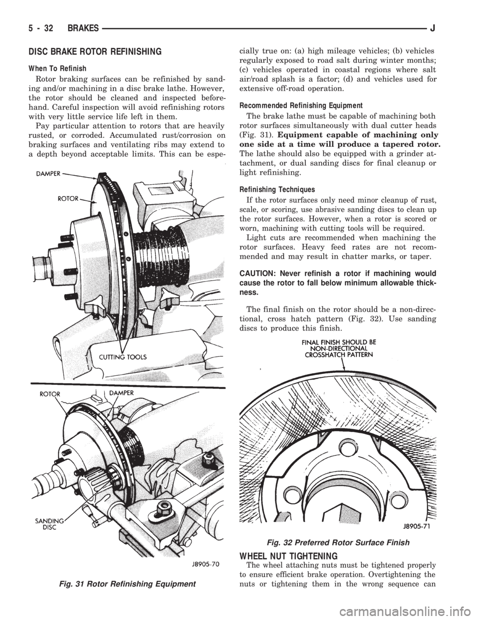
The brake lathe must be capable of machining both
rotor surfaces simultaneously with dual cutter heads
(Fig. 31).Equipment capable of machining only
one side at a time will produce a tapered rotor.
The lathe should also be equipped with a grinder at-
tachment, or dual sanding discs for final cleanup or
light refinishing.
Refinishing Techniques
If the rotor surfaces only need minor cleanup of rust,
scale, or scoring, use abrasive sanding discs to clean up
the rotor surfaces. However, when a rotor is scored or
worn, machining with cutting tools will be required.
Light cuts are recommended when machining the
rotor surfaces. Heavy feed rates are not recom-
mended and may result in chatter marks, or taper.
CAUTION: Never refinish a rotor if machining would
cause the rotor to fall below minimum allowable thick-
ness.
The final finish on the rotor should be a non-direc-
tional, cross hatch pattern (Fig. 32). Use sanding
discs to produce this finish.
WHEEL NUT TIGHTENING
The wheel attaching nuts must be tightened properly
to ensure efficient brake operation. Overtightening the
nuts or tightening them in the wrong sequence can
Fig. 31 Rotor Refinishing Equipment
Fig. 32 Preferred Rotor Surface Finish
5 - 32 BRAKESJ
Page 180 of 1784
cause distortion of the brake rotors and drums.
Impact wrenches are not recommended for tighten-
ing wheel nuts. A torque wrench should be used for
this purpose.
A light coat of LPS Anti-Corrosion spray lube
around the hub face and on the studs will cut down
on rust/corrosion formation.
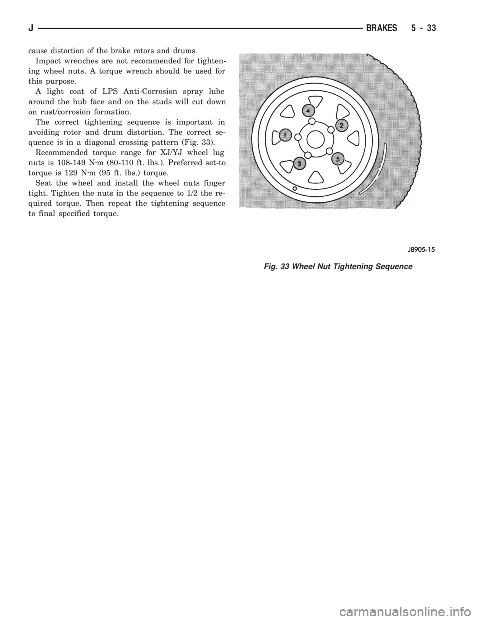
The correct tightening sequence is important in
avoiding rotor and drum distortion. The correct se-
quence is in a diagonal crossing pattern (Fig. 33).
Recommended torque range for XJ/YJ wheel lug
nuts is 108-149 Nzm (80-110 ft. lbs.). Preferred set-to
torque is 129 Nzm (95 ft. lbs.) torque.
Seat the wheel and install the wheel nuts finger
tight. Tighten the nuts in the sequence to 1/2 the re-
quired torque. Then repeat the tightening sequence
to final specified torque.
Fig. 33 Wheel Nut Tightening Sequence
JBRAKES 5 - 33
Page 181 of 1784
DRUM BRAKES
INDEX
page page
Brake Drum Refinishing.................... 37
Drum Brake Adjustment................... 35
Drum Brakeshoe Installation................ 34
Drum Brakeshoe Removal (Figs. 1 and 2)...... 34
Support Plate Replacement................. 37Wheel Cylinder Installation................. 37
Wheel Cylinder Overhaul (Figs. 8 and 9)....... 36
Wheel Cylinder Removal................... 36
Wheel Nut Tightening..................... 37
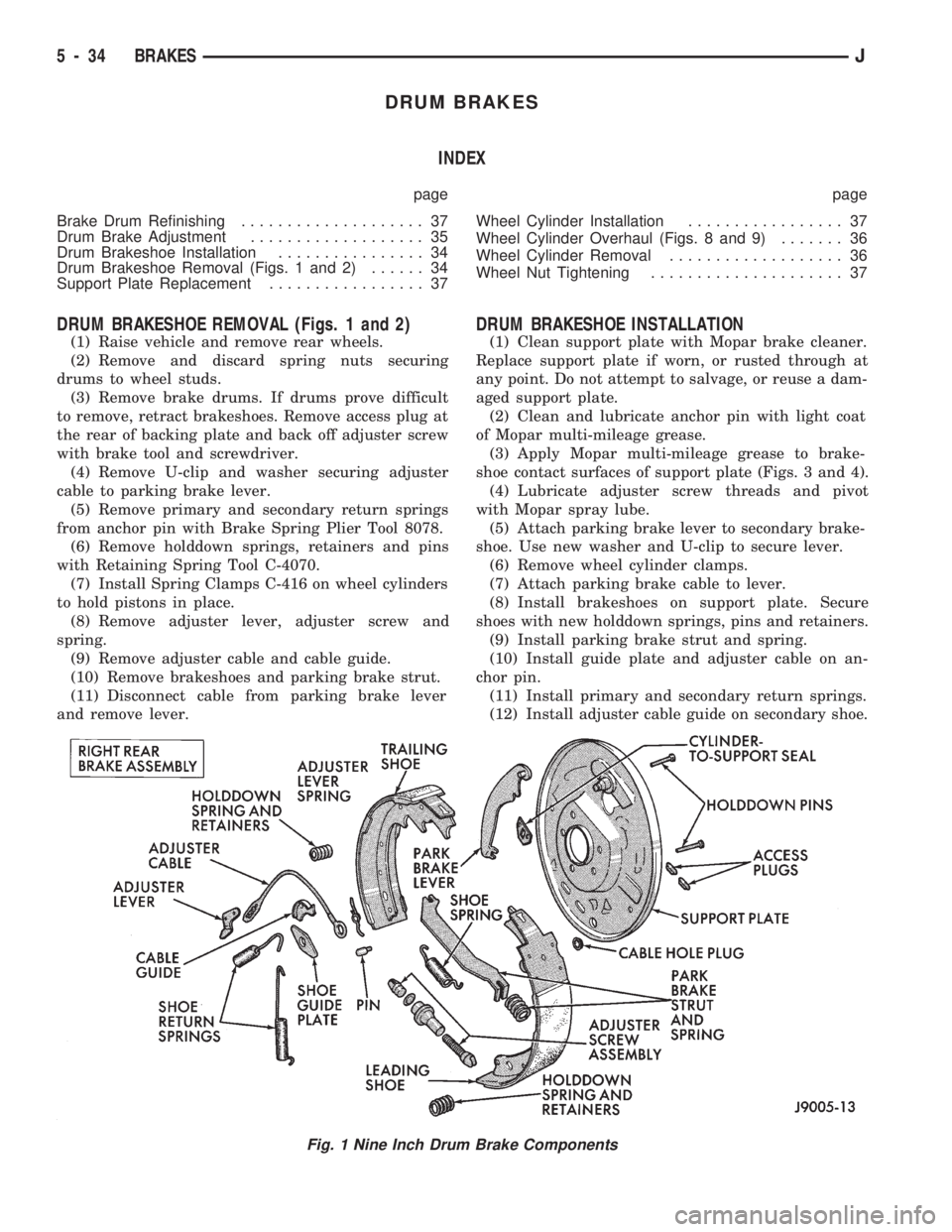
DRUM BRAKESHOE REMOVAL (Figs. 1 and 2)
(1) Raise vehicle and remove rear wheels.
(2) Remove and discard spring nuts securing
drums to wheel studs.
(3) Remove brake drums. If drums prove difficult
to remove, retract brakeshoes. Remove access plug at
the rear of backing plate and back off adjuster screw
with brake tool and screwdriver.
(4) Remove U-clip and washer securing adjuster
cable to parking brake lever.
(5) Remove primary and secondary return springs
from anchor pin with Brake Spring Plier Tool 8078.
(6) Remove holddown springs, retainers and pins
with Retaining Spring Tool C-4070.
(7) Install Spring Clamps C-416 on wheel cylinders
to hold pistons in place.
(8) Remove adjuster lever, adjuster screw and
spring.
(9) Remove adjuster cable and cable guide.
(10) Remove brakeshoes and parking brake strut.
(11) Disconnect cable from parking brake lever
and remove lever.
DRUM BRAKESHOE INSTALLATION
(1) Clean support plate with Mopar brake cleaner.
Replace support plate if worn, or rusted through at
any point. Do not attempt to salvage, or reuse a dam-
aged support plate.
(2) Clean and lubricate anchor pin with light coat
of Mopar multi-mileage grease.
(3) Apply Mopar multi-mileage grease to brake-
shoe contact surfaces of support plate (Figs. 3 and 4).
(4) Lubricate adjuster screw threads and pivot
with Mopar spray lube.
(5) Attach parking brake lever to secondary brake-
shoe. Use new washer and U-clip to secure lever.
(6) Remove wheel cylinder clamps.
(7) Attach parking brake cable to lever.
(8) Install brakeshoes on support plate. Secure
shoes with new holddown springs, pins and retainers.
(9) Install parking brake strut and spring.
(10) Install guide plate and adjuster cable on an-
chor pin.
(11) Install primary and secondary return springs.
(12) Install adjuster cable guide on secondary shoe.
Fig. 1 Nine Inch Drum Brake Components
5 - 34 BRAKESJ
Page 183 of 1784
(2) Verify that left/right automatic adjuster lever
and cable are properly connected.
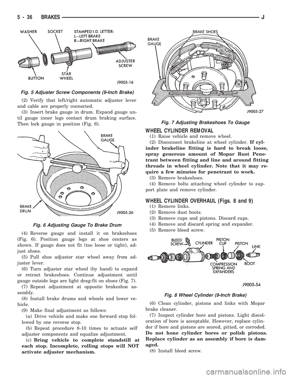
(3) Insert brake gauge in drum. Expand gauge un-
til gauge inner legs contact drum braking surface.
Then lock gauge in position (Fig. 6).
(4) Reverse gauge and install it on brakeshoes
(Fig. 6). Position gauge legs at shoe centers as
shown. If gauge does not fit (too loose or tight), ad-
just shoes.
(5) Pull shoe adjuster star wheel away from ad-
juster lever.
(6) Turn adjuster star wheel (by hand) to expand
or retract brakeshoes. Continue adjustment until
gauge outside legs are light drag-fit on shoes (Fig. 7).
(7) Repeat adjustment at opposite brakeshoe as-
sembly.
(8) Install brake drums and wheels and lower ve-
hicle.
(9) Make final adjustment as follows:
(a) Drive vehicle and make one forward stop fol-
lowed by one reverse stop.
(b) Repeat procedure 8-10 times to actuate self
adjuster components and equalize adjustment.
(c)Bring vehicle to complete standstill at
each stop. Incomplete, rolling stops will NOT
activate adjuster mechanism.
WHEEL CYLINDER REMOVAL
(1) Raise vehicle and remove wheel.
(2) Disconnect brakeline at wheel cylinder.If cyl-
inder brakeline fitting is hard to break loose,
spray generous amount of Mopar Rust Pene-
trant between fitting and line and around fitting
threads in wheel cylinder. Note that it may re-
quire a few minutes for penetrant to work.
(3) Remove brakeshoes.
(4) Remove bolts attaching wheel cylinder to sup-
port plate and remove cylinder.
WHEEL CYLINDER OVERHAUL (Figs. 8 and 9)
(1) Remove links.
(2) Remove dust boots.
(3) Remove cups and pistons. Discard cups.
(4) Remove and discard spring and expander.
(5) Remove bleed screw.
(6) Clean cylinder, pistons and links with Mopar
brake cleaner.
(7) Inspect cylinder bore and pistons. Light discol-
oration of bore is acceptable. However, replace cylin-
der if bore and pistons are scored, pitted, or corroded.
Do not hone cylinder bores or polish pistons.
Replace cylinder as an assembly if bore is dam-
aged.
(8) Install bleed screw.
Fig. 5 Adjuster Screw Components (9-Inch Brake)
Fig. 6 Adjusting Gauge To Brake Drum
Fig. 7 Adjusting Brakeshoes To Gauge
Fig. 8 Wheel Cylinder (9-Inch Brake)
5 - 36 BRAKESJ
Page 184 of 1784
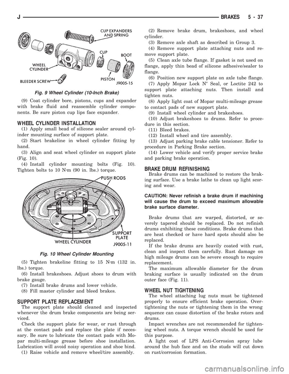
(9) Coat cylinder bore, pistons, cups and expander
with brake fluid and reassemble cylinder compo-
nents. Be sure piston cup lips face expander.
WHEEL CYLINDER INSTALLATION
(1) Apply small bead of silicone sealer around cyl-
inder mounting surface of support plate.
(2) Start brakeline in wheel cylinder fitting by
hand.
(3) Align and seat wheel cylinder on support plate
(Fig. 10).
(4) Install cylinder mounting bolts (Fig. 10).
Tighten bolts to 10 Nzm (90 in. lbs.) torque.
(5) Tighten brakeline fitting to 15 Nzm (132 in.
lbs.) torque.
(6) Install brakeshoes. Adjust shoes to drum with
brake gauge.
(7) Install brake drums and lower vehicle.
(8) Fill master cylinder and bleed brakes.
SUPPORT PLATE REPLACEMENT
The support plate should cleaned and inspected
whenever the drum brake components are being ser-
viced.
Check the support plate for wear, or rust through
at the contact pads and replace the plate if neces-
sary. Be sure to lubricate the contact pads with Mo-
par multi-mileage grease before shoe installation.
Lubrication will avoid noisy operation and shoe bind.
(1) Raise vehicle and remove wheel/tire assembly.(2) Remove brake drum, brakeshoes, and wheel
cylinder.
(3) Remove axle shaft as described in Group 3.
(4) Remove support plate attaching nuts and re-
move support plate.
(5) Clean axle tube flange. If gasket is not used on
flange, apply thin bead of silicone adhesive/sealer to
flange.
(6) Position new support plate on axle tube flange.
(7) Apply Mopar Lock N9Seal, or Loctite 242 to
support plate attaching nuts. Then install and
tighten nuts.
(8) Apply light coat of Mopar multi-mileage grease
to contact pads of new support plate.
(9) Install wheel cylinder and brakeshoes.
(10) Adjust brakeshoes to drums. Refer to proce-
dure in this section.
(11) Bleed brakes.
(12) Install wheel and tire assembly.
(13) Adjust parking brake cable tensioner. Refer to
procedure in Parking Brake section.
(14) Lower vehicle and verify proper service brake
and parking brake operation.
BRAKE DRUM REFINISHING
Brake drums can be machined to restore the brak-
ing surface. Use a brake lathe to clean up light scor-
ing and wear.
CAUTION: Never refinish a brake drum if machining
will cause the drum to exceed maximum allowable
brake surface diameter.
Brake drums that are warped, distorted, or se-
verely tapered should be replaced. Do not refinish
drums exhibiting these conditions. Brake drums that
are heat checked or have hard spots should also be
replaced.
If the brake drums are heavily coated with rust,
clean and inspect them carefully. Rust damage on
high mileage drums can be severe enough to require
replacement.
The maximum allowable diameter for the drum
braking surface is usually indicated on the drum
outer face (Fig. 11).
WHEEL NUT TIGHTENING
The wheel attaching lug nuts must be tightened
properly to ensure efficient brake operation. Over-
tightening the nuts or tightening them in the wrong
sequence can cause distortion of the brake rotors and
drums.
Impact wrenches are not recommended for tighten-
ing wheel nuts. A torque wrench should be used for
this purpose.
A light coat of LPS Anti-Corrosion spray lube
around the hub face and on the studs will cut down
on rust/corrosion formation.
Fig. 9 Wheel Cylinder (10-Inch Brake)
Fig. 10 Wheel Cylinder Mounting
JBRAKES 5 - 37
Page 186 of 1784
ABS SYSTEM OPERATION
INDEX
page page
Acceleration Switch....................... 41
Combination Valve....................... 42
Electronic Control Unit (ECU)............... 41
General Information....................... 39
Hydraulic Control Unit (HCU)................ 39
Ignition Switch........................... 42Master Cylinder.......................... 40
Pedal Travel Sensor...................... 41
Power Brake Booster..................... 40
System Relays.......................... 42
System Warning Lights.................... 42
Wheel Speed Sensors..................... 41
GENERAL INFORMATION
The Jeep antilock brake system (ABS) is an elec-
tronically operated, all-wheel brake control system.
Major components include the master cylinder, vac-
uum power brake booster, ECU, hydraulic control
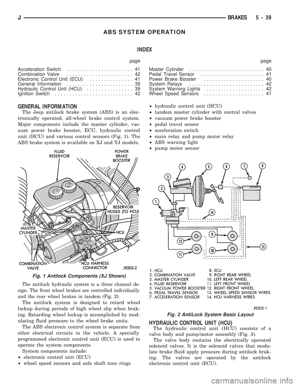
unit (HCU) and various control sensors (Fig. 1). The
ABS brake system is available on XJ and YJ models.
The antilock hydraulic system is a three channel de-
sign. The front wheel brakes are controlled individually
and the rear wheel brakes in tandem (Fig. 2).
The antilock system is designed to retard wheel
lockup during periods of high wheel slip when brak-
ing. Retarding wheel lockup is accomplished by mod-
ulating fluid pressure to the wheel brake units.
The ABS electronic control system is separate from
other electrical circuits in the vehicle. A specially
programmed electronic control unit (ECU) is used to
operate the system components.
System components include:
²electronic control unit (ECU)
²wheel speed sensors and axle shaft tone rings²hydraulic control unit (HCU)
²tandem master cylinder with central valves
²vacuum power brake booster
²pedal travel sensor
²acceleration switch
²main relay and pump motor relay
²ABS warning light
²pump motor sensor
HYDRAULIC CONTROL UNIT (HCU)
The hydraulic control unit (HCU) consists of a
valve body and pump/motor assembly (Fig. 3).
The valve body contains the electrically operated
solenoid valves. It is the solenoid valves that modu-
late brake fluid apply pressure during antilock brak-
ing. The valves are operated by the antilock
electronic control unit (ECU).
Fig. 1 Antilock Components (XJ Shown)
Fig. 2 AntiLock System Basic Layout
JBRAKES 5 - 39
Page 188 of 1784
4). The engine intake manifold serves as the vacuum
source for booster operation.
The booster is mounted on the engine compartment
side of the dash panel. The master cylinder is
mounted on attaching studs at the front of the
booster. The master cylinder central valves are di-
rectly actuated by the booster push rod.
The pedal travel sensor is mounted in the forward
face of the booster shell. The sensor plunger is actu-
ated by the booster diaphragm plate.
PEDAL TRAVEL SENSOR
The pedal travel sensor signals brake pedal posi-
tion to the antilock ECU. The sensor signal is based
on changes in electrical resistance. The resistance
changes occur in steps that are generated by changes
in brake pedal position. A resistance signal gener-
ated by changing brake pedal position, will cause the
ECU to run the antilock pump when necessary.
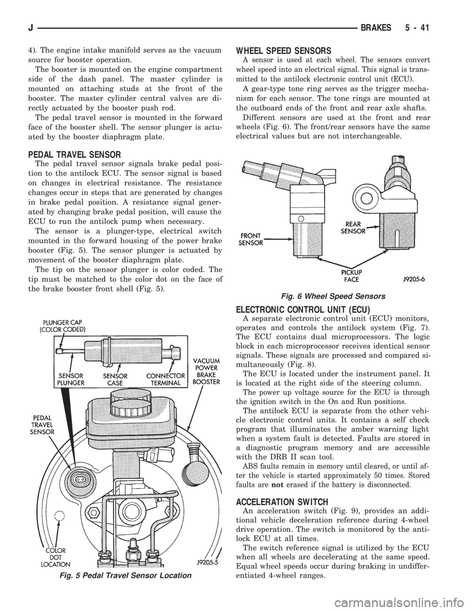
The sensor is a plunger-type, electrical switch
mounted in the forward housing of the power brake
booster (Fig. 5). The sensor plunger is actuated by
movement of the booster diaphragm plate.
The tip on the sensor plunger is color coded. The
tip must be matched to the color dot on the face of
the brake booster front shell (Fig. 5).
WHEEL SPEED SENSORS
A sensor is used at each wheel. The sensors convert
wheel speed into an electrical signal. This signal is trans-
mitted to the antilock electronic control unit (ECU).
A gear-type tone ring serves as the trigger mecha-
nism for each sensor. The tone rings are mounted at
the outboard ends of the front and rear axle shafts.
Different sensors are used at the front and rear
wheels (Fig. 6). The front/rear sensors have the same
electrical values but are not interchangeable.
ELECTRONIC CONTROL UNIT (ECU)
A separate electronic control unit (ECU) monitors,
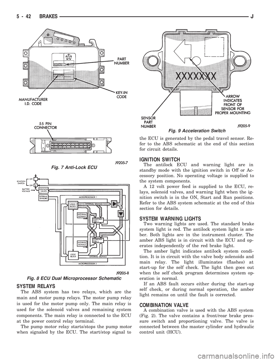
operates and controls the antilock system (Fig. 7).
The ECU contains dual microprocessors. The logic
block in each microprocessor receives identical sensor
signals. These signals are processed and compared si-
multaneously (Fig. 8).
The ECU is located under the instrument panel. It
is located at the right side of the steering column.
The power up voltage source for the ECU is through
the ignition switch in the On and Run positions.
The antilock ECU is separate from the other vehi-
cle electronic control units. It contains a self check
program that illuminates the amber warning light
when a system fault is detected. Faults are stored in
a diagnostic program memory and are accessible
with the DRB II scan tool.
ABS faults remain in memory until cleared, or until af-
ter the vehicle is started approximately 50 times. Stored
faults arenoterased if the battery is disconnected.
ACCELERATION SWITCH
An acceleration switch (Fig. 9), provides an addi-
tional vehicle deceleration reference during 4-wheel
drive operation. The switch is monitored by the anti-
lock ECU at all times.
The switch reference signal is utilized by the ECU
when all wheels are decelerating at the same speed.
Equal wheel speeds occur during braking in undiffer-
entiated 4-wheel ranges.
Fig. 5 Pedal Travel Sensor Location
Fig. 6 Wheel Speed Sensors
JBRAKES 5 - 41
Page 189 of 1784
SYSTEM RELAYS
The ABS system has two relays, which are the
main and motor pump relays. The motor pump relay
is used for the motor pump only. The main relay is
used for the solenoid valves and remaining system
components. The main relay is connected to the ECU
at the power control relay terminal.
The pump motor relay starts/stops the pump motor
when signaled by the ECU. The start/stop signal tothe ECU is generated by the pedal travel sensor. Re-
fer to the ABS schematic at the end of this section
for circuit details.
IGNITION SWITCH
The antilock ECU and warning light are in
standby mode with the ignition switch in Off or Ac-
cessory position. No operating voltage is supplied to
the system components.
A 12 volt power feed is supplied to the ECU, re-
lays, solenoid valves, and warning light when the ig-
nition switch is in the ON, Start and Run positions.
Refer to the ABS system schematic at the end of this
section for details.
SYSTEM WARNING LIGHTS
Two warning lights are used. The standard brake
system light is red. The antilock system light is am-
ber. Both lights are in the instrument cluster. The
amber ABS light is in circuit with the ECU and op-
erates independently of the red brake light.
The amber light indicates antilock system condi-
tion. It is in circuit with the valve body solenoids and
main relay. The light illuminates (flashes) at
start-up for the self check. The light then goes out
when the self check program determines system op-
eration is normal.
If an ABS fault occurs either during the start-up
self check, or during normal operation, the amber
light remains on until the fault is corrected.
COMBINATION VALVE
A combination valve is used with the ABS system
(Fig. 2). The valve contains a front/rear brake pres-
sure switch and proportioning valve. The valve is
connected between the master cylinder and hydraulic
control unit (HCU).
Fig. 7 Anti-Lock ECU
Fig. 8 ECU Dual Microprocessor Schematic
Fig. 9 Acceleration Switch
5 - 42 BRAKESJ